1
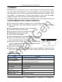
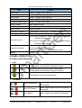
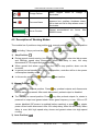
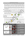
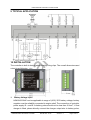
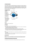
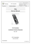
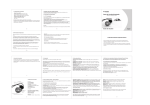
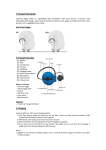
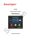
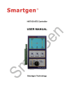
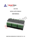
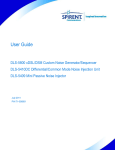
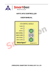
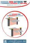
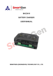
HGM190/190HC Generator Control Module User Manual Smartgen Technology HGM190/190HC Generator Control Module Smartgen Technology Co., Ltd No.28 Jinsuo Road Zhengzhou Henan Province P. R. China Tel: 0086-371-67988888/67981888 0086-371-67991553/67992951/67992952 0086-371-67981000(overseas) National Free Tel: 4000318139 Fax: 0086-371-67992952/67981000 Web: http://www.smartgen.com.cn http://www.smartgen.cn Email: [email protected] All rights reserved. No part of this publication may be reproduced in any material form (including photocopying or storing in any medium by electronic means or other) without the written permission of the copyright holder. Applications for the copyright holder‟s written permission to reproduce any part of this publication should be addressed to Smartgen Technology at the address above. Any reference to trademarked product names used within this publication is owned by their respective companies. Smartgen Technology reserves the right to change the contents of this document without prior notice. Software Version Date Version 2007-11-01 1.1 2010-08-12 1.2 2011-06-13 1.3 2011-12-22 1.4 Notes Original release Change over speed time from 3s to 1.5s Change the name of the company “Smartgen electronics” to “Smartgen Technology”. Modify Typical Application. HGM190/190HC Generator Controller ISSUE 2011-12-22 Version 1.4 Page 2 of 11 HGM190/190HC Generator Control Module CONTENTS 1 SUMMARY ..............................................................................................................................................4 2 PERFORMANCE AND CHARACTERISTICS .........................................................................................4 3 SPECIFICATION .....................................................................................................................................4 4 PANEL OPERATION...............................................................................................................................5 4.1 Keys and Indicators .............................................................................................. 5 4.2 Description of Working Modes .............................................................................. 6 5 SETTING .................................................................................................................................................7 6 ALARM AND PROTECTION ...................................................................................................................8 7 CONNECTIONS ......................................................................................................................................9 8 COMMISSIONING...................................................................................................................................9 9 TYPICAL APPLICATION .......................................................................................................................10 10 INSTALLATION ...................................................................................................................................10 11 FAULT FINDING ................................................................................................................................. 11 HGM190/190HC Generator Controller ISSUE 2011-12-22 Version 1.4 Page 3 of 11 HGM190/190HC Generator Control Module 1 SUMMARY HGM190/190HC is a generator control module designed to start and stop the engine via a key switch and pushbuttons on the front panel or remote start signal. When detecting faults (low oil pressure, high water/cylinder temperature, auxiliary alarm, over speed), it will disconnect fuel relay and energize to stop. LED annunciator displays the faults, which can offer real and effective alarm information. HGM190HC adds hours counter based on HGM190, other functions are as the same. 2 PERFORMANCE AND CHARACTERISTICS ◆ Wide range of DC supply, can adapt to 12V or 24V starting battery; ◆ Low oil pressure, high water/cylinder temperature, over speed protection and indication; ◆ With charge failure indication: warn, not shutdown; ◆ An auxiliary shutdown alarm signal; ◆ Speed signal comes from generator frequnecy; ◆ LED displays various alarm states; ◆ Hours counter LCD display; ◆ Rated rotating speed (over speed threshold) can be set; ◆ With fuel output, start output, pre-heat, stop output and common alarm/idle output. All are relay output; ◆ Idle speed control. Output can be set as idle/high speed output by dialing the switch, or the port is common alarm output; (See the picture) ◆ Idle delay is programmable; ◆ Modular structure design, ABS plastic case, plug-in installation, compact structure with small volume, advanced SCU control, stable performance and convenient operation. 3 SPECIFICATION Items Contents Working Voltage DC8.0V to 35.0V continuous Power Consumption Speed Signal Input Engine Speed Over Speed Speed When Disconnect Standby (12V: 0.12W, 24V: 0.24W) Working (12V: 0.5W, 24V:1W) (1~24)V (RMS) <10kHz Can be set 114% of rated Crank Can be set Charge Failure Volt <3V 4 Digital Inputs Connect to B- active HGM190/190HC Generator Controller ISSUE 2011-12-22 Version 1.4 Page 4 of 11 HGM190/190HC Generator Control Module Items Contents Start Output 1Amp DC28V relay output B- Preheat Output 1Amp DC28V relay output B- Fuel Output 1Amp DC28V relay output B- Stop Output 1Amp DC28V relay output B- Programmable Output 1Amp DC28V relay output Hours Counter Max 99999.9 hours Case Dimensions 84mm x72mm x 35mm Panel Cutout 78mm x 66mm Operation Condition Temperature: (-30~+70)ºC Storage Condition Temperature: (-40~+80)ºC Humidity: (20~90)% IP55: when waterproof rubber gasket added between controller and its panel. Protection Level IP42: when waterproof rubber gasket not added between controller and its panel. Object: among input/output/power Insulation Intensity Quote standard: IEC688-1992 Test way: AC1.5kV/1m Weight 3mA leakage current 0.25kg 4 PANEL OPERATION 4.1 Keys and Indicators keys Preheat Manual Set In Manual Mode, press this to output preheat signal; In Stop Mode or Auto Mode, this key is inactive. In Manual Mode, press this key to start genset; In Stop Mode or Auto Mode, this key is inactive. Pressing this key can set parameters. Indicators High Temperature When engine stops for high temperature, it illuminates. Low Oil Pressure When engine stops for low oil pressure, it illuminates. Over Speed When engine over speed, it illuminates. HGM190/190HC Generator Controller ISSUE 2011-12-22 Version 1.4 Page 5 of 11 HGM190/190HC Generator Control Module Charge Failure When engine illuminates. failed to charge, it Common Alarm When over speed, temperature high, oil pressure low, auxiliary shutdown alarm, fail to start and fail to stop alarms occur, it illuminates. Hours Counter Genset accumulated run hours. Max 99999.9 hours. 4.2 Description of Working Modes The module has 3 positions: stop position ( ), manual position ( ( ) including 3 keys: pre-heat key ( ), start key ( ) and auto position ) and set key ( ). 1) Stop Position ( ) ◆ During genset normal running, turn the key to stop position, enter into idle process and idle/high speed relay disconnect. When idle delay is over, fuel relay disconnects, ETS outputs and genset stops. ◆ When genset fault alarm occurs, turn the key to stop position, alarm can be removed. ◆ In genset normal standby, turn key to stop position, controller will be in low power consumption standby mode. ◆ In this mode, preheat key 2) Manual Position ( and start key are inactive. ) ◆ Turn the key to manual position. Press key, preheat outputs and disconnects before starter is powered. After crank disconnect, preheat output is disabled. ◆ Turn the key to manual position. Press key, after preheat outputs 1s, starter is powered to output and genset starts. When gens frequency is over 15Hz or OP sensor disabled (OP sensor is enabled before cranking) or press key, starter power off and crank disconnect. After 10s‟ safety delay, enter into idle delay. When delay is over, idle/ high speed relay closes and genset enters into high speed running. 3) Auto Position ( ) HGM190/190HC Generator Controller ISSUE 2011-12-22 Version 1.4 Page 6 of 11 HGM190/190HC Generator Control Module ◆ Turn the key to Auto position. When remote start signal active (connect to B-), after 2s delay, genset will start automatically, preheat delay begin outputting. When the delay is over, fuel outputs, and preheat output disconnects after 1s, crank begins (Maximum 3 times to start, 8 seconds for cranking and 10 seconds interval. If crank disconnect within 3 times, module is started; if fail to disconnect every time, common alarm annunciator illuminates and relay outputs). When engine speed exceeds crank speed (can be set), crank disconnect and enter into 10s‟ idle delay. When idle delay is over, idle/high speed relay close and the genset run in high speed. Note: During crank interval delay, fuel relay disconnects, 3s‟ delay begins. Once delay is over, ETS (energize to stop) disconnect, fuel outputs, and preheat output disconnect before cranking. ◆ When remote start input inactive, enter into idle process after 10s‟ delay. During this period, idle/high speed output disconnects. Once idle delay over, fuel disconnects, ETS output, genset will stop automatically. When genset at rest, ETS and idle output disconnect. ◆ Under this mode, preheat key , start key and set key are disable. 5 SETTING Setting contents: Idle time, rotating speed when crank disconnect and rated speed. 1. Setting procedures of idle time and rotating speed Turn the key to stop position ( ), pressing set key ( ) for at least 5 seconds can enter into editing status. Idle time and rotating speed when crank disconnect can be set. Press preheat key ( press ) to choose items (with to choose the value of setting item (with and , indicating), then and See the below table: Item Value 5 seconds 10 seconds(Default) 15 seconds 20 seconds 30 seconds 60 seconds 120 seconds 180 seconds 12% 18% 24% (Default) 30% 36% Idle time Rotating speed (percentage of rated speed) HGM190/190HC Generator Controller indicating). ISSUE 2011-12-22 Version 1.4 Page 7 of 11 HGM190/190HC Generator Control Module Reserved Reserved Reserved Note: means light is illuminating while means not. 2. Setting procedures of rated speed Turn the key to Auto position ( into setting status. Press speed, press ), long pressing to preheat and at least 5 seconds to enter to crank. When reaching rated to set the speed. See the below table: After setting, turn the key to stop position ( ) to exit the setting status and genset stops. Item Result Failed Rated speed Successful Note: a) During setting rated speed, over speed is not protected; b) If rotating speed is 0, the setting is invalid; c) Rated speed can be repeatedly set under programming mode; d) If there is no need to set rated speed, turn the key to Auto position without starting the engine and go to the stop position directly; e) If programmable output is set as common alarm output, idle delay is 0. 6 ALARM AND PROTECTION Low Oil Pressure: After crank disconnect, detecting begins after delay 10s. Low OP lasts for 2s, alarm to shutdown. High Temperature: After crank disconnect, detecting begins after delay 10s. High temperature lasts for 2s, alarm to shutdown. Over Speed: Detect when crank disconnect. Over speed lasts for 1.5s, alarm to shutdown. Charge Fail: Detect when high speed running. When D+ (WL) voltage under 3V and lasts for 3s, warn, not shutdown. Auxiliary Stop Alarm: Detect in Auto mode and Manual mode, do not detect in stop mode. Fail to Start: Under normal condition, fail to start within 3 times. Fail to stop: When fuel signal has disconnected for 30s, but genset not stop, then the input is active. Lose of Speed Signal: After crank disconnect, detect when delay 10s. If lasting for 5 seconds, alarm to shutdown. Common Alarm: when over speed, high temperature, low oil pressure, auxiliary shutdown alarm, lose of speed signal, fail to start and fail to stop happen, alarm HGM190/190HC Generator Controller ISSUE 2011-12-22 Version 1.4 Page 8 of 11 HGM190/190HC Generator Control Module annunciator illuminates and common alarm outputs. 7 CONNECTIONS Terminals description Terminal 1 (B-): Connected to plant battery negative. Terminal 2 (B+): Connected to plant battery positive. Terminal 3 (Fuel Output): Fuel Output (B+), Connected to fuel relay. Terminal 4 (Start Output): Start Output (B+), Connected to start relay. Terminal 5 (Pre-heat Output): Pre-heat Output (B+). Terminal 6 (Aux. Shutdown Input): auxiliary shutdown alarm input, connect to Bactive. Terminal 7 (D+): Connect to alternator WL (or D+) terminal. When charging fails (D+ voltage<3V), annunciator on the panel illuminates. (indication only, not shutdown) Terminal 8 (Low Oil Pressure Input): Low Oil Pressure Input port, connect B- active. Terminal 9 (High Engine Temp input): High water/cylinder temperature input port, connect to B- active. Terminal 10 (L), 11(N): Connect to AC voltage signal for detecting crank disconnect and over speed protection. Terminal 12 (Config. Output): Config. Output (B+), can be set as idle/high speed output or common alarm via dial switch of the controller. Terminal 13 (Stop Output): Energize to stop (ETS) (B+). Terminal 14 (Remote Start Input): Remote start input port,connect to B- active. 8 COMMISSIONING Please make the under procedures checking before commissioning, 1. Check all the connections are correct and wires diameter is suitable; 2. Ensure that the controller DC power has insurance, controller„s positive and negative connected to start battery are correct; 3. Auxiliary alarm input is connected to start battery negative via normal close contact of emergency stop button and insurance; 4. Take proper action to prevent engine to crank disconnect (e. g. Remove the connection wire of fuel valve). If checking is OK, energize start battery; 5. Set controller into Manual mode, press “start” button, genset will start. After the setting times, controller will send fail to start signal; press “stop” key to reset the controller. 6. Recover the action of stop engine start (e. g. Connect wire of fuel valve), press start button again, genset will start. If everything goes well, genset will enter into normal running. During this period, please watch for engine‟s running situations and AC generator‟s voltage and frequency. If abnormal, stop genset running and check all connections according to this manual. 7. Set controller into Auto mode, enable remote start input and start the engine. If there is any wrong during engine running, stop to check the connections according to the manual. 8. If there are any other questions, please contact Smartgen‟s service. HGM190/190HC Generator Controller ISSUE 2011-12-22 Version 1.4 Page 9 of 11 HGM190/190HC Generator Control Module 9 TYPICAL APPLICATION 10 INSTALLATION The controller is built-in design which fixed by fixing clips. The overall dimensions and cutout is as following: 1. Battery Voltage Input HGM190/190HC can be applicable to range of (8-35) VDC battery voltage; battery negative must be reliability connected to engine shell. The connection of controller power supply B + and B- to battery poles should not be less than 2.5mm2, if float charger is fitted, please directly connect the charger output wire to battery poles, HGM190/190HC Generator Controller ISSUE 2011-12-22 Version 1.4 Page 10 of 11 HGM190/190HC Generator Control Module and then separately connect the wirings from the battery poles to the power supply output of the controller in case that the charger will interfere with the normal operation of the controller. 2. Output and Expansion Relay All output of the controller is relay contacts output, if there is need to expand output relays, please expand follow current diode in both ends of the relay coil (when extended relay coil links DC) or increase resistance and capacitance loop (when extended relay coil links AC) in order to prevent interference with the controller or other equipments. 3. Withstand Voltage Test When the controller has been installed in the control panel, if you want to have withstand voltage test, please disconnect all terminals in the controller lest high voltage damages the controller. 11 FAULT FINDING Fault Remedy Check starting batteries; Controller no response with Check controller connection wirings; power. Check DC fuse. Genset shutdown Check if the engine temperature is too high; Check the genset AC voltage; Check DC fuse. Low oil pressure alarm after Check the oil pressure sensor and its crank disconnect connections. High water/cylinder temp Check the temperature sensor and its alarm after crank disconnect connections. Crank not disconnect Check fuel circuit and its connections; Check starting battery; Check speed sensor and its connections; Refer to engine manual. Starter no response Check starter connections; Check starting battery. HGM190/190HC Generator Controller ISSUE 2011-12-22 Version 1.4 Page 11 of 11