1
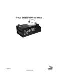
Ice Jet
Operator’s Manual
www.ultratecfx.com
VER. 04.11.12
Table of Contents
Introduction................................................................................. 3
Warning....................................................................................... 3
Important Safety Instructions:.................................................... 3
Technical Specifications.............................................................. 4
Technical Drawings.................................................................... 4
Operating Procedure.................................................................. 5
Ideal Use and Preventative Measures....................................... 6
CO2 Workseet............................................................................. 6
Warranty...................................................................................... 7
Contact Information................................................................... 7
Note: Please read entire manual before operating the Ice Jet
2
www.ultratecfx.com
Introduction
The Ice Jet is an atmospheric effect created by the release of CO2. It creates a white plume like those seen from
high-flying jet aircraft. The chilled blast from the CO2 temporarily condenses air born moisture into cloudbursts.
The Ice Jet is available as a high or low pressure CO2 unit. It is available in 120 or 240 volts.
Warning
Important Safety Instructions:
1. Do not touch or expose skin in the discharge nozzle path.
2. Ensure sufficient air exchange vs. CO2 released.
3. Ensure that this unit is grounded at all times. Failure to do so may result in serious injury.
4. Ensure that operation of the machine is supervised by suitably trained and authorised personnel.
5. Do not modify the machine or use a machine which has been damaged in any way.
6. Protect the Ice Jet from direct weather effects and wet locations.
7. Do not use nitrogen with this product.
www.ultratecfx.com
3
Technical Specifications
Model:
Ice Jet
Part Number:
CLF 2140 - Ice Jet 120 volt Low
CLF 2142 - Ice Jet - 220-240 volt Low
Length:
4in
10cm
Width:
7in
18cm
Height:
10in
225cm
Net Weight:
4lbs
2kg
Power Rating:
120 or 220-240 vac; less than 1 amp.
Fluid:
Ultratec Special Effects Water Base Fog Fluid
Low Pressure:
Operates at 350psi from a Dewar Tank.
Flow Rate of 18 lbs/ minute.
High Pressure:
Operates at 1000psi from a cylinder.
Flow Rate of 18 lbs/ minute.
Required Equipment:
CLF 2160 - CGA 320 CO2 Dewar Tank Fitting (3/8”)
CLF 2154 - Ice Jet Hose 10’
CLF 2153 - Ice Jet Hose 15’
CLF 2155 - Ice Jet Hose 25’
CLF 2156 - Ice Jet Hose 50’
CLF 2157 - Ice Jet Hose 75’
CLF 2158 - Ice Jet Hose 100’
Approvals:
Field Certification by Q.P.S.
Technical Drawings
4
www.ultratecfx.com
OperatInG
Operating Procedure
prOCeDure
WARNING: Always use two wrenches when working on the valve. Excess
torque on the valve body will cause permanent damage. This will VOID any
WARNING - Always use two wrenches
warranty claims.
when working on the valve. Excess
torque on the valve body will cause
NOTE: Before operating the Ice Jet a site
review is required.
the will
Ice Jet
is
permanent
damage.AsThis
VOID
capable of dispensing large quantities any
of CO2
in a room,
the air exchange
warranty
claims.
properties of the room must be determined (see CO2 Worksheet). Due to
the nature of the Dewar tank, some CO2 is consumed to keep the liquid
CO2 cold. This CO2 is released around the tank. If early delivery is required
anticipate the loss of CO2 and the storage ventilation requirements. As Ice
Jets require large tanks, have safe handling and transportation requirements
NOTE: Before operating the Ice-Jet a site review is required. As the
prearranged.
Ice-Jet
is
of rated
dispensing
large quantities of CO2 in a room,
properly
andand
fitting
While connecting the tank adapter check
thatWear
thecapable
sealing
disk
is clean
the
air
exchange
properties
of
the
room must be determined (see
not worn. Inspect the burst disk for damage.safety
Inspectglasses
the hosesand
for gloves.
wear,
CO2
Worksheet).
Due
to
the
nature
blisters and cracks. While connecting the fittings
ensurefrom
theypressure
are seatedand of the Dewar tank, some CO2
Hazards
is consumed
toare
keep
the liquid
CO2 cold. This CO2 is released
properly. Replace any component, which
is not
in good
repair.
freezing
present.
On the
aroundPlace
the the
tank.
is required anticipate the loss
low-pressure
Ice-Jet
tank
the
The Ice Jet produces thrust when operating.
Ice If
Jetearly
on a delivery
flat
surface
of
CO2
and
the
storage
ventilation
requirements. As both high
and securely fasten it. Four mounting holes are
provided.
pressure
should be above 300
and low Ice-Jets require large tanks, have safe handling and
pressure
Wear properly rated and fitting safety glassespsi.
andOpen
gloves.the
Hazards
from builder
transportation
requirements
prearranged.
1 hour before
time.
pressure and freezing are present. On the low-pressure
Ice Jetshow
tank the
Connectbuilder
to the1liquid
line on
pressure should be above 300 psi. Open the pressure
hour before
While
connecting
show time. Connect to the liquid line on
the the
tank.tank. the tank adapter check that the sealing disk is
clean and not worn. Inspect the burst disk for damage. Inspect the
hosesOn
forawear,
blisters and
cracks. While connecting the fittings
high-pressure
Ice-Jet
The Ice Jet produces a loud noise and ensure
high velocity
flow
during
operation.
they
are
seated
properly.
Replace any component, which is
use only a dip tube equipped
Ensure the safety of persons and property
around
the
nozzle
discharge.
If
not in cylinder
good repair.
which will allow liquid
controlling the Ice Jet from a lighting console place it on a non-dimming
withdrawal.
Slowly
crack
circuit to prevent damage. Apply the correct voltage
and the
solenoid
willthe
The Ice-Jet
produces
thrust when
operating. Place the Ice-Jet on
delivery
valve,
watching
and
open. You will note the sound change as the liquid CO2 makes its way to
the
a flat
surface
and
securely
fasten
it. Four mounting holes are
listening
forThe
leaks.
If all
is okay,
valve. This could take several seconds for
long
hose runs.
red band
on
provided.
thenthe
open
valves
then
the nozzle adjusts the amount of air sucked into
CO2the
stream.
Thefully,
size of
the effect varies with the moisture concentration
of the
the valve
air. More
moisture
close
back
1/2 turn.
Mounting Holes
means more cloud formation.
When finished with the Ice Jet turn off the tank valve (CAUTION: it may be
cold)! Turn on the Ice Jet to allow the pressure to escape.
Leave the valve on several extra seconds to allow
of theproduces
CO2 to www.lemaitrefx.com
flash
off. Now
hose and
The all
Ice-Jet
a loud
noisedisconnect
and high the
velocity
flowtank
during
adapter.
operation. Ensure the safety of persons and property around the
nozzle discharge. If controlling the Ice-Jet from a lighting console
place it on a non-dimming circuit to prevent damage. Apply the
correct voltage and the solenoid will open. You will note the sound
change as the liquid CO2 makes it’s way to the valve. This could
take several seconds for long hose runs. The red band on the
nozzle adjusts the amount of air sucked into the CO2 stream.
The size of the effect varies with the moisture concentration of
the air. More moisture means more cloud formation.
www.lemaitrefx.com
www.ultratecfx.com
5
Ideal Use and Preventative Measures
1. If possible, use the shortest CO2 delivery hose. This will help prevent solids from accumulating.
2. Do not leave hose out in direct sunlight.
3. If possible, insulate the hose from the area temperature.
4. An excessive, short burst of CO2 could jam the Ice Jet open.
5. If possible, purge system before using.
CO2 Workseet
Data
1 lb. = 8.741 (scf) gas
1 lb. = 0.118 (gal) liquid
Specific gravity = 1.53 for gas
Air has 21% oxygen and 0.03% of CO2
CO2 is heavier than air and will sink to lower areas and displace the air.
OSHA exposure 0.5% for 8 hours (TWA) or 3% for 15 minutes (STEL)
Things to watch for when using CO2 are the reduction of the oxygen content and the collecting of CO2 in low or
confined spaces. By planning the location and duration of the equipment safe operation can be implemented. CO2
monitors can be installed in low or confined areas to alert personnel of the presence of a hazard. Portable monitors
can be used to spot check for the safe exposure levels. If the location is open and only needs an exposure limit this can
be done by calculation. To calculate the oxygen depletion you must know the size of the area and the amount of CO2
added. The user’s manual should give the rate of CO2 the equipment consumes.
Example
An Ice Jet outputs 18 lb. of CO2 per minute.
Our room is 75’ x 75’ x 18’ for a volume of 101,250 cu.ft. or approximately 100,000 cu.ft..
If we ran 2 Ice Jets for 1 minute we would add 36 lb. of CO2 to the room.
36 x 8.741 = 315 cu.ft. of CO2 added to the room.
If the room contained 0.03% of CO2 before we had 30 cu.ft. of CO2 present. (100,000 x 0.0003 = 30)
Now we have 315 + 30 = 345 of CO2 or 345/100,000 = 0.345%
This simple calculation leaves out several factors. All rooms have air exchange, which should be several times per hour.
Replacing the air to keep people comfortable requires more exchange than what’s accounted for by their breathing.
This will reduce the CO2 concentration significantly. The other major factor is the local concentration of CO2 until it is
dispersed into the room. This is the responsibility of the operator to ensure that exposure in this area is safe.
6
www.ultratecfx.com
Warranty
Warranty:
Hardware products come with a one year warranty on parts and labor. Unless stated otherwise,
this will refer to manufacturer defects only. All warranty is based on destination of the original
sale. Any additional costs incurred are the responsibility of the Dealer and/ or the customer.
Abuse or poor maintenance is not accepted. Proof of purchase or proof of sale must always
accompany all warranty returns. An RA (Return Authorization) number must be noted on
the outside of each box being returned to our facility. Any package(s) without an RA number
clearly marked, will not be accepted by our receiving department. Freight on warranty items are
freight prepaid to our facility and we will prepay freight back to your facility following repair.
This will be done by the most economical means available. Should you require the item expressreturned, the dealer is responsible for request indication and any difference in freight cost.
Export Distributors are required to carry out the warranty repair, parts will be supplied by
Ultratec.
Return Policy:
Return of any product must be done within 30 days of purchase. The package must be
returned freight prepaid and the RA number clearly marked on the outside of the box.
Warning:
Ultratec Special Effects considers all of it’s product to be safe for use in the application it was
intended. Ultratec Special Effects takes no responsibility for misuse or incorrect use. Always
refer to the Product Manual for proper use.
Contact Information
Head Office
Ultratec Special Effects
1960 Blue Heron Drive
London, Ontario N6H 5L9
Direct: 519-659-7972
Toll Free: 866-534-5557
Fax: 519-659-7713
Europe Office
Ultratec Special Effects GmbH
Dieselstrasse 30-40
60314
Frankfurt am Main
Germany
Canadian Shipping Address
(For All Canadian Repairs)
Ultratec Special Effects
1960 Blue Heron Drive
London, Ontario N6H 5L9
USA Shipping Address
(For All USA Repairs)
Ultratec Special Effects
657 Gadson Street
Groveland, Florida 34736
Please remember to include the RA Number on all items being shipped
for repairs.
To retrieve an RA Number visit www.ultratecfx.com and click on the
“Service” section. Then click on “Return Authorization Request” which is
located on the left hand side of the page.
If you have any questions or require assistance please contact service at
519-951-3357/866-534-5557 or by email at [email protected].
Direct: 49-69-87-000-1850
Fax: 49-69-87-000-1899
www.ultratecfx.com
7