1
SAFETY PRECAUTIONS
(Always read these instructions before using this product.)
Before using this product, thoroughly read this manual and the relevant manuals introduced in this manual
and pay careful attention to safety and handle the products properly.
The precautions given in this manual are concerned with this product. For the safety precautions of the
system, refer to the User's Manual for each controller.
In this manual, the safety precautions are ranked as "
WARNING" and "
CAUTION".
WARNING
Indicates that incorrect handling may cause hazardous conditions,
resulting in death or severe injury.
CAUTION
Indicates that incorrect handling may cause hazardous conditions,
resulting in miner or moderate injury or property damage.
Note that the
CAUTION level may lead to serious consequences according to the circumstances.
Always follow the precautions of both levels because they are important for personal safety.
Please save this manual to make it accessible when required and always forward it to the end user.
[Design Instructions]
WARNING
● When data change, program change, or status control is performed from a personal computer to a running controller,
create an interlock circuit outside the programmable controller to ensure that the whole system always operates safely.
Furthermore, for the online operations performed from a personal computer to a controller, the corrective actions against a
communication error due to such as a cable connection fault should be predetermined as a system.
[Startup/Maintenance Instructions]
CAUTION
● The online operations performed from a personal computer to a running controller (Program change, operating status
change such as RUN-STOP switching, and remote control operation) have to be executed after the manual has been
carefully read and the safety has been ensured.
When changing a program while a controller is RUN, it may cause a program corruption in some operating conditions.
Fully understand the precautions described in the manuals and Help function of each controller before use.
A-1
CONDITIONS OF USE FOR THE PRODUCT
(1) Mitsubishi programmable controller ("the PRODUCT") shall be used in conditions;
i) where any problem, fault or failure occurring in the PRODUCT, if any, shall not lead to any major or
serious accident; and
ii) where the backup and fail-safe function are systematically or automatically provided outside of the
PRODUCT for the case of any problem, fault or failure occurring in the PRODUCT.
(2) The PRODUCT has been designed and manufactured for the purpose of being used in general
industries.
MITSUBISHI SHALL HAVE NO RESPONSIBILITY OR LIABILITY (INCLUDING, BUT NOT LIMITED
TO ANY AND ALL RESPONSIBILITY OR LIABILITY BASED ON CONTRACT, WARRANTY, TORT,
PRODUCT LIABILITY) FOR ANY INJURY OR DEATH TO PERSONS OR LOSS OR DAMAGE TO
PROPERTY CAUSED BY the PRODUCT THAT ARE OPERATED OR USED IN APPLICATION NOT
INTENDED OR EXCLUDED BY INSTRUCTIONS, PRECAUTIONS, OR WARNING CONTAINED IN
MITSUBISHI'S USER, INSTRUCTION AND/OR SAFETY MANUALS, TECHNICAL BULLETINS AND
GUIDELINES FOR the PRODUCT.
("Prohibited Application")
Prohibited Applications include, but not limited to, the use of the PRODUCT in;
• Nuclear Power Plants and any other power plants operated by Power companies, and/or any other
cases in which the public could be affected if any problem or fault occurs in the PRODUCT.
• Railway companies or Public service purposes, and/or any other cases in which establishment of a
special quality assurance system is required by the Purchaser or End User.
• Aircraft or Aerospace, Medical applications, Train equipment, transport equipment such as Elevator
and Escalator, Incineration and Fuel devices, Vehicles, Manned transportation, Equipment for
Recreation and Amusement, and Safety devices, handling of Nuclear or Hazardous Materials or
Chemicals, Mining and Drilling, and/or other applications where there is a significant risk of injury to
the public or property.
Notwithstanding the above, restrictions Mitsubishi may in its sole discretion, authorize use of the
PRODUCT in one or more of the Prohibited Applications, provided that the usage of the PRODUCT is
limited only for the specific applications agreed to by Mitsubishi and provided further that no special
quality assurance or fail-safe, redundant or other safety features which exceed the general
specifications of the PRODUCTs are required. For details, please contact the Mitsubishi representative
in your region.
A-2
REVISIONS
The manual number is written at the bottom left of the back cover.
Print date
Revision
Manual number
Oct., 2009
SH-080902ENG-A
First edition
Apr., 2010
SH-080902ENG-B
Model Addition
MELSEC-L series
Addition
CONDITIONS OF USE FOR THE PRODUCT, Section 3.4, Section 3.10
Correction
MANUALS, GENERIC TERMS AND ABBREVIATIONS IN THIS MANUAL,
Section 1.1, Section 1.2, Section 2.1, Section 3.3, Section 3.4, Section 3.5,
Section 3.6, Section 3.7, Section 3.8, Section 3.9, Section 3.10, Section 3.12,
Section 4.1, Section 4.2, Section 4.3, Section 4.4, Section 5.1, Section 5.2,
Section 6.2
Sep., 2010
SH-080902ENG-C
Model Addition
MELSEC-FX series
Addition
Section 3.4, Section 3.10
Correction
GENERIC TERMS AND ABBREVIATIONS IN THIS MANUAL,
Section 1.1, Section 1.2, Section 2.1, Section 3.1, Section 3.3, Section 3.4,
Section 3.5, Section 3.6, Section 3.7, Section 3.8, Section 3.9, Section 3.11,
Section 3.13, Section 4.1, Section 4.2, Section 4.3, Section 4.4, Section 5.1,
Section 5.2, Section 6.2
Apr., 2011
SH-080902ENG-D
Addition
GENERIC TERMS AND ABBREVIATIONS IN THIS MANUAL
Correction
HOW TO READ THIS MANUAL, Section 1.1, Section 1.2, Section 2.1, Section 3.1,
Section 3.3, Section 3.4, Section 3.5, Section 3.6, Section 3.7, Section 3.8,
Section 4.1, Section 4.2, Section 4.4, Section 5.1, Section 5.2, Section 6.2
Nov., 2011
SH-080902ENG-E
Addition
MANUALS, GENERIC TERMS AND ABBREVIATIONS IN THIS MANUAL,
Section 3.4.4
Correction
Section 1.1, Section 1.2, Section 2.1, Section 3.1, Section 3.2, Section 3.3,
Section 3.4, Section 3.5, Section 3.8, Section 3.9, Section 3.11, Section 3.13,
Section 4.1, Section 4.2, Section 4.3, Section 4.4, Section 5.2, Section 6.1,
Section 6.2
Jun., 2012
SH-080902ENG-F
Correction
Section 1.1, Section 1.2, Section 2.1, Section 3.4, Section 3.5, Section 3.8,
Section 4.1, Section 4.2, Section 4.3, Section 4.4, Section 6.2
Nov., 2012
SH-080902ENG-G
Correction
Section 1.2, Section 3.2, Section 3.4, Section 3.11, Section 5.2
A-3
Print date
Jun., 2013
Revision
Manual number
SH-080902ENG-H
Addition
Section 3.4.5
Correction
Section 2.1, Section 3.4.1, Section 3.4.4, Section 3.11
Dec., 2013
SH-080902ENG-I
Addition
Section 3.4.6, Section 3.4.7
Correction
MANUALS, GENERIC TERMS AND ABBREVIATIONS IN THIS MANUAL,
Section 3.4.2, Section 3.4.3, Section 3.4.4, Section 3.5.1, Section 3.6, Section 3.7,
Section 3.9, Section 3.11, Section 5.2
Japanese Manual Version SH-080763-J
This manual confers no industrial property rights or any rights of any other kind, nor does it confer any patent licenses.
Mitsubishi Electric Corporation cannot be held responsible for any problems involving industrial property rights which may occur
as a result of using the contents noted in this manual.
© 2009 MITSUBISHI ELECTRIC CORPORATION
A-4
INTRODUCTION
Thank you for purchasing the Mitsubishi integrated FA software, MELSOFT series.
Before using the product, thoroughly read this manual to develop full familiarity with the functions and performance
to ensure correct use.
CONTENTS
SAFETY PRECAUTIONS ...................................................................................................................... A - 1
REVISIONS ........................................................................................................................................... A - 3
INTRODUCTION ................................................................................................................................... A - 5
CONTENTS ........................................................................................................................................... A - 5
MANUALS.............................................................................................................................................. A - 7
HOW TO READ THIS MANUAL .......................................................................................................... A - 11
GENERIC TERMS AND ABBREVIATIONS IN THIS MANUAL........................................................... A - 13
1
2
OVERVIEW
1.1
MELSOFT iQ Works
1-2
1.2
Features
1-3
SCREEN CONFIGURATION
2.1
3
1 - 1 to 1 - 10
Screen Configuration
OPERATING PROCEDURE OF MELSOFT NAVIGATOR
2 - 1 to 2 - 4
2-2
3 - 1 to 3 - 60
3.1
Procedure of MELSOFT Navigator from Start to End
3-2
3.2
Starting MELSOFT Navigator
3-3
3.3
Creating Workspaces
3-4
3.4
Creating System Configuration Diagram
3-8
3.5
3.4.1
System configuration to be created .............................................................................................. 3 - 8
3.4.2
Creating module configuration diagrams...................................................................................... 3 - 9
3.4.3
Creating network configuration diagrams ................................................................................... 3 - 20
3.4.4
Creating CC-Link configuration diagrams................................................................................... 3 - 22
3.4.5
Creating AnyWireASLINK configuration diagrams ..................................................................... 3 - 24
3.4.6
Creating Ethernet configuration diagrams .................................................................................. 3 - 26
3.4.7
Creating CC IE Field configuration diagrams ............................................................................. 3 - 28
Creating Projects
3 - 30
3.5.1
Creating new projects................................................................................................................. 3 - 30
3.5.2
Allocating projects to controllers................................................................................................. 3 - 35
3.6
Setting Parameters
3 - 38
3.7
Checking System Configuration
3 - 47
A-5
3.8
4
3.7.2
Checking power supply capacity and I/O points ........................................................................ 3 - 48
Editing Projects
3 - 49
3.8.1
Editing projects........................................................................................................................... 3 - 49
3.8.2
Utilizing existing projects (import) .............................................................................................. 3 - 50
Reading/Writing/Verifying Controller Data
3 - 53
3.10
Saving Workspaces
3 - 56
3.10.1
Saving workspaces with specified names.................................................................................. 3 - 56
3.10.2
Overwriting workspaces ............................................................................................................. 3 - 57
3.11
Printing Workspaces
3 - 58
3.12
Closing Workspaces
3 - 59
3.13
Exiting MELSOFT Navigator
3 - 60
USING SYSTEM LABELS
4.2
6
Checking system configuration .................................................................................................. 3 - 47
3.9
4.1
5
3.7.1
Registering System Labels in MELSOFT Navigator
4 - 1 to 4 - 20
4-2
4.1.1
Registering system labels in MELSOFT Navigator ...................................................................... 4 - 3
4.1.2
Assigning devices to system labels.............................................................................................. 4 - 5
4.1.3
Using system labels in GT Designer3 .......................................................................................... 4 - 8
Utilizing Existing Labels as System Labels
4 - 11
4.2.1
Registering labels as system labels ........................................................................................... 4 - 12
4.2.2
Using system labels in motion controller projects ...................................................................... 4 - 15
4.3
Using System Labels on another personal computer
4 - 17
4.4
Checking System Labels
4 - 19
CREATING SYSTEM BACKUP DATA
5 - 1 to 5 - 6
5.1
Setting Batch Read Password
5-2
5.2
Executing Batch Read Function
5-4
USING PROGRAM JUMP FUNCTION
6 - 1 to 6 - 5
6.1
Example of System Configuration
6-2
6.2
Program Jump Function
6-3
A-6
■
MANUALS
The manuals related to this product are shown below.
Refer to the following tables when ordering required manuals.
Related manuals
1) MELSOFT Navigator
For details of operations, refer to the Help function of MELSOFT Navigator.
2)
GX Works2
Manual name
Manual number
(Model code)
GX Works2 Version 1 Operating Manual (Common)
Explains the system configuration of GX Works2 and the functions common to a Simple project and
Structured project such as parameter setting, operation method for the online function. (Sold separately)
SH-080779ENG
(13JU63)
GX Works2 Version 1 Operating Manual (Simple Project)
Explains operation methods such as creating and monitoring programs in Simple project of GX Works2.
(Sold separately)
SH-080780ENG
(13JU64)
GX Works2 Version 1 Operating Manual (Structured Project)
Explains operation methods such as creating and monitoring programs in Structured project of GX
Works2.
(Sold separately)
SH-080781ENG
(13JU65)
GX Works2 Beginner's Manual (Simple Project)
Explains fundamental operation methods such as creating, editing, and monitoring programs in Simple
project for users inexperienced with GX Works2.
(Sold separately)
SH-080787ENG
(13JZ22)
GX Works2 Beginner's Manual (Structured Project)
Explains fundamental operation methods such as creating, editing, and monitoring programs in
Structured project for users inexperienced with GX Works2.
(Sold separately)
SH-080788ENG
(13JZ23)
A-7
3)
GT Designer3
Manual name
4)
GT Designer3 Version 1 Screen Design Manual (Fundamentals)
Explains the system configuration, screen configuration, basic operations for dialog boxes, methods
such as creating new project and transferring data to GOT, and convenient screen editing operations of
GT Designer3.
(Sold separately)
SH-080866ENG
(1D7MB9)
GT Designer3 Version 1 Screen Design Manual (Functions) (1/2, 2/2)
Explains common settings, object function specifications, setting methods, and arranging methods of GT
Designer3.
(Sold separately)
SH-080867ENG
(1D7MC1)
GT Designer3 (GOT2000) Screen Design Manual
Explains the system configuration, screen configuration, basic operations for dialog boxes, methods
such as creating new project and transferring data to GOT, and convenient screen editing operations of
GT Designer3.
(Sold separately)
SH-081220ENG
(1D7ML9)
GOT1000 Series Connection Manual (Mitsubishi Products) for GT Works3
Explains Mitsubishi products that can be connected to GOT and their connection method.
(Sold separately)
SH-080868ENG
(1D7MC2)
GOT1000 Series Connection Manual (Non-Mitsubishi Products 1) for GT Works3
Explains non-Mitsubishi products that can be connected to GOT and their connection method.
(Sold separately)
SH-080869ENG
(1D7MC3)
GOT1000 Series Connection Manual (Non-Mitsubishi Products 2) for GT Works3
Explains non-Mitsubishi products that can be connected to GOT and their connection method.
(Sold separately)
SH-080870ENG
(1D7MC4)
GOT1000 Series Connection Manual (Microcomputer, MODBUS Products, Peripherals) for GT Works3
Explains the connection method between GOT and peripherals such as a bar code reader.
(Sold separately)
SH-080871ENG
(1D7MC5)
GOT2000 Series Connection Manual (Mitsubishi Product) For GT Works3 Version1
Explains Mitsubishi products that can be connected to GOT and their connection method.
(Sold separately)
SH-081197ENG
(1D7MJ8)
GOT2000 Series Connection Manual (Non Mitsubishi Product 1) For GT Works3 Version1
Explains non-Mitsubishi products that can be connected to GOT and their connection method.
(Sold separately)
SH-081198ENG
(1D7MJ9)
GOT2000 Series Connection Manual (Non Mitsubishi Product 2) For GT Works3 Version1
Explains non-Mitsubishi products that can be connected to GOT and their connection method.
(Sold separately)
SH-081199ENG
(1D7MK1)
GOT2000 Series Connection Manual (Microcomputer, MODBUS Products, Peripherals) For GT Works3
Version1
Explains the connection method between GOT and peripherals such as a bar code reader.
(Sold separately)
SH-081200ENG
(1D7MK2)
GT Simulator3 Version 1 Operating Manual
Explains the system configuration, screen configuration, and operation methods of GT Simulator3 used
in GOT1000 series (GT16/GT15/GT11) and GOT-A900 series.
(Sold separately)
SH-080861ENG
(1D7MB1)
GT SoftGOT1000 Version 3 Operating Manual for GT Works3
Explains the system configuration, screen configuration, and operation methods of monitoring software
GT Soft GOT1000.
(Sold separately)
SH-080860ENG
(1D7MA9)
GT SoftGOT2000 Version1 Operating Manual
Explains the system configuration, screen configuration, and operation methods of monitoring software
GT Soft GOT2000.
(Sold separately)
SH-081201ENG
(1D7MK3)
MT Developer2
Refer to the Help function of MT Developer2.
A-8
Manual number
(Model code)
5)
6)
Motion Controllers
Manual name
Manual number
(Model code)
Q173DCPU/Q172DCPU Motion controller Programming Manual (COMMON)
Explains the Multiple CPU system configuration, performance specifications, common parameters,
auxiliary/applied functions, and error lists.
(Optional)
IB-0300134
(1XB928)
Q173DCPU/Q172DCPU Motion controller (SV13/SV22) Programming Manual (Motion SFC)
Explains the functions, programming, debugging, and error lists of Motion SFC.
(Optional)
IB-0300135
(1XB929)
Q173DCPU/Q172DCPU Motion controller (SV13/SV22) Programming Manual (REAL MODE)
Explains the servo parameters, positioning instructions, device lists, and error lists.
(Optional)
IB-0300136
(1XB930)
Q173DCPU/Q172DCPU Motion controller (SV22) Programming Manual (VIRTUAL MODE)
Explains the dedicated instructions, servo parameters, positioning instructions for mechanical system
program comprised of a virtual main shaft or mechanical module required to execute the synchronous
control, device lists, and error lists.
(Optional)
IB-0300137
(1XB931)
Q173HCPU/Q172HCPU Motion controller Programming Manual (COMMON)
Explains the Multiple CPU system configuration, performance specifications, common parameters,
auxiliary/applied functions and error lists.
(Optional)
IB-0300111
(1XB911)
Q173HCPU/Q172HCPU Motion controller (SV13/SV22) Programming Manual (Motion SFC)
Explains the functions, programming, debugging, and error lists of Motion SFC.
(Optional)
IB-0300112
(1XB912)
Q173HCPU/Q172HCPU Motion controller (SV13/SV22) Programming Manual (REAL MODE)
Explains the servo parameters, positioning instructions, device list, and error lists.
(Optional)
IB-0300113
(1XB913)
Q173HCPU/Q172HCPU Motion controller (SV22) Programming Manual (VIRTUAL MODE)
Explains the dedicated instructions, servo parameters, positioning instructions for mechanical system
program comprised of a virtual main shaft or mechanical module required to execute the synchronous
control, device lists, and error lists.
(Optional)
IB-0300114
(1XB914)
Q173HCPU/Q172HCPU Motion controller (SV43) Programming Manual
Explains the dedicated instructions to execute the positioning control by Motion program of EIA language
(G-code), servo parameters, positioning instructions, device list, and error lists.
(Optional)
IB-0300115
(1XB915)
Q173CPU(N)/Q172CPU(N) Motion controller (SV13/SV22) Programming Manual (Motion SFC)
Explains the Multiple CPU system configuration, performance specifications, functions, programming,
and error codes of the Motion SFC.
(Optional)
IB-0300042
(1XB781)
Q173CPU(N)/Q172CPU(N) Motion controller (SV13/SV22) Programming Manual (REAL MODE)
Explains the servo parameters, positioning instructions, device list, and error lists.
(Optional)
IB-0300043
(1XB782)
Q173CPU(N)/Q172CPU(N) Motion controller (SV22) Programming Manual (VIRTUAL MODE)
Explains the dedicated instructions, servo parameters, positioning instructions for mechanical system
program comprised of a virtual main shaft or mechanical module required to execute the synchronous
control, device lists, and error lists.
(Optional)
IB-0300044
(1XB783)
Q173CPU(N)/Q172CPU(N) Motion controller (SV43) Programming Manual
Explains the dedicated instructions to execute the positioning control by Motion program of EIA language
(G-code), Multiple CPU system configuration, performance specifications, functions, programming,
debugging, servo parameters, positioning instructions, device list, and error lists.
(Optional)
IB-0300070
(1CT784)
RT ToolBox2
Manual name
CR750/700/500 series RT ToolBox2 / RT ToolBox2 mini User's Manual
Explains operation methods such as creating and monitoring programs, and connecting with robots.
Manual number
(Model code)
BFP-A8618
The Operating Manual is included on the DVD-ROM/CD-ROM of the software package in PDF file format.
Manuals in printed form are sold separately for single purchase. Order a manual by quoting the manual number
(model code) listed in the table above.
A-9
● Purpose of this manual
This manual explains the features and operations of iQ Platform supporting engineering environment
MELSOFT iQ Works.
Manuals and the Help function for reference are listed in the following table according to their
purpose.
For information such as the contents and number of each manual, refer to the list of 'Related
manuals'.
Purpose
Manuals and HELP function for reference
Creating GX Works2 projects
GX Works2 Version 1 Operating Manual (Common)
GX Works2 Version 1 Operating Manual (Simple Project)
GX Works2 Version 1 Operating Manual (Structured Project)
GX Works2 Beginner's Manual (Simple Project)
GX Works2 Beginner's Manual (Structured Project)
Creating MT Developer2 projects
Help function of MT Developer2
Creating GT Designer3 projects
GT Designer3 Version 1 Screen Design Manual (For GOT 1000 Series)
GT Designer3 (GOT2000) Screen Design Manual
Creating RT ToolBox2 projects
CR750/700/500 series RT ToolBox2 / RT ToolBox2 mini User's Manual
Using system labels
Using data backup function
Using program jump function
A - 10
GX Works2 Version 1 Operating Manual (Common)
GX Works2 Version 1 Operating Manual (Simple Project)
GX Works2 Version 1 Operating Manual (Structured Project)
GX Works2 Beginner's Manual (Simple Project)
GX Works2 Beginner's Manual (Structured Project)
Help function of MT Developer2
Motion controller programming manual of Q173D/Q172D, Q173H/Q172H, Q173/Q172
■
HOW TO READ THIS MANUAL
This section explains how to read this manual according to your purpose when using MELSOFT iQ
Works.
Please use this manual with referring to the following descriptions.
1)
To learn about the overview of MELSOFT iQ Works
Chapter 1 OVERVIEW
Chapter 1 explains the features of MELSOFT iQ Works.
2)
To learn about the screen configuration of MELSOFT iQ Works
Chapter 2 SCREEN CONFIGURATION
Chapter 2 explains the screen configuration of MELSOFT Navigator.
3)
To learn about the operating procedures of MELSOFT Navigator
Chapter 3 OPERATING PROCEDURE OF MELSOFT NAVIGATOR
Chapter 3 explains a sequence of the basic operation from start-up to creating and saving methods
of workspaces and projects.
4)
To learn about the system labels
Chapter 4 USING SYSTEM LABELS
Chapter 4 explains the functions to utilize labels used in a project for controller projects in a
workspace.
5)
To learn about the data backup
Chapter 5 CREATING SYSTEM BACKUP DATA
Chapter 5 explains the functions to read programmable controller projects, motion controller
projects, and GOT projects from respective controllers in batch and create their backup data using
MELSOFT Navigator.
6)
To learn about the program jump function
Chapter 6 USING PROGRAM JUMP FUNCTION
Chapter 6 explains the function which can start motion SFC programs/servo programs, that are
linked with motion controller programs, using the SFCS and SVST instructions of ladder programs.
A - 11
This explains notes requiring attention or useful functions relating to the information given on the
same page.
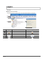
● Symbols used in this manual
The following shows the symbols used in this manual with descriptions and examples.
No.
Symbol
[
]
Description
Menu name on a menu bar
Example
[Workspace]
Toolbar icon
"
"
Item name in a workspace
"
"
Item name in a screen
"Configuration diagram B"
"Open Startup Screen at Start"
Button on a screen
-
A - 12
Keyboard key
Ctrl
■
GENERIC TERMS AND ABBREVIATIONS IN THIS MANUAL
This manual uses the generic terms and abbreviations listed in the following table to discuss the
software packages and programmable controller CPUs. Corresponding module models are also listed if
needed.
Generic term and abbreviation
Description
MELSOFT Navigator
Generic product name of the integrated development environment for SWnDND-IQWK-E/
SWnDNC-IQWK-E (iQ Platform supporting engineering environment MELSOFT iQ Works)
(n: version)
GX Works2
Generic product name for SWnDNC-GXW2-E
(n: version)
MELSOFT Navigator compatible GX Works2 is GX Works2Version 1.15R or later.
MT Developer2
Generic product name for SWnDNC-MTW2-E
(n: version)
MELSOFT Navigator compatible MT Developer2 is MT Developer2 Version 1.09K or later.
GT Designer3
Generic product name for SWnD5C-GTWK3-E
(n: version)
MELSOFT Navigator compatible GT Designer3 is GT Designer3 Version 1.05F or later.
GX Developer
Generic product name for SWnD5C-GPPW-E
(n: version)
MELSOFT Navigator compatible GX Developer is GX Developer Version 8.95Z or later.
RT ToolBox2
Generic product name for 3D-11C-WINE/3D-12C-WINE
MELSOFT Navigator compatible RT ToolBox2 is RT ToolBox2 Version 2.00A or later.
Q series
Generic term for MELSEC-Q series
L series
Generic term for MELSEC-L series
FX series
Generic term for MELSEC-F series
Controller
Generic terms for programmable controller, motion controller, and GOT
Network
Generic terms for CC-Link IE controller network, MELSECNET/H, and Ethernet
Personal computer
Generic term for personal computers on which Windows® operates
GOT
Generic term for Mitsubishi Graphic Operation Terminal GOT1000 series and GOT2000
Series
System configuration diagram
Generic terms for network configuration and module configuration
GX Works2 project
Projects that created/saved with GX Works2 (GX Works2 format project)
GX Developer project
Projects that created/saved with GX Developer (GX Developer format project)
A - 13
MEMO
A - 14
OVERVIEW
2
SCREEN
CONFIGURATION
1
OVERVIEW
1
This chapter explains the features of MELSOFT iQ Works.
OPERATING PROCEDURE
OF MELSOFT NAVIGATOR
3
4
USING SYSTEM
LABELS
MELSOFT iQ Works. . . . . . . . . . . . . . . . . . . . . . . . . . . . . . . . . . 1-2
Features . . . . . . . . . . . . . . . . . . . . . . . . . . . . . . . . . . . . . . . . . . . 1-3
CREATING SYSTEM
BACKUP DATA
5
6
USING PROGRAM
JUMP FUNCTION
1.1
1.2
1-1
iQ Works
1 OVERVIEW
1.1
MELSOFT iQ Works
MELSOFT iQ Works is an integrated engineering software product which includes GX Works2, MT Developer2, GT
Designer3, and RT ToolBox2.
While sharing design information such as system designs and programming in the whole control system, the
system designing efficiency and the programming efficiency are improved, and thus the total programming cost is
reduced.
This manual explains the system management method using MELSOFT Navigator.
Q series, L series, and FX series are supported in MELSOFT Navigator, however, this manual explains the
operations of Q series.
MELSOFT iQ Works
GX Works2
(PLC programming and
maintenance software)
MT Developer2
(Motion programming and
maintenance software)
GT Designer3
(HMI screen creation software)
RT ToolBox2
(Robot total engineering
support software)
MELSOFT Navigator
(System management software)
Share design information
among software products
Design information
database
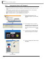
To start MELSOFT Navigator and engineering software products, select an item registered in the start menu by
following the procedures below.
• MELSOFT Navigator : Select [MELSOFT Application] ⇒ [MELSOFT iQ Works] ⇒ [MELSOFT Navigator].
• GX Works2
• MT Developer2
• GT Designer3
• RT ToolBox2
1-2
: Select [MELSOFT Application] ⇒ [GX Works2] ⇒ [GX Works2].
: Select [MELSOFT Application] ⇒ [MT Works2] ⇒ [MT Developer2].
: Select [MELSOFT Application] ⇒ [GT Works3] ⇒ [GT Designer3].
: Select [MELSOFT Application] ⇒ [RT ToolBox2] ⇒ [RT ToolBox2].
1.2 Features
1
Features
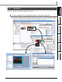
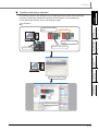
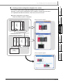
Project management using graphical system configuration diagrams
2
Projects are managed by using graphically displayed diagrams of the actual hardware equipment
configuration of the whole system, linking each equipment and the project.
3
OPERATING PROCEDURE
OF MELSOFT NAVIGATOR
Activate the Module Configuration
window by double-clicking a module
configuration diagram on the
Network Configuration window.
USING SYSTEM
LABELS
4
Activate the project linked
to the respective module by
double clicking a module on
the Module Configuration
window.
CREATING SYSTEM
BACKUP DATA
5
6
USING PROGRAM
JUMP FUNCTION
■
OVERVIEW
This section explains the features of MELSOFT iQ Works.
SCREEN
CONFIGURATION
1.2
GOT project
Programmable controller project
1-3
iQ Works
1 OVERVIEW
■
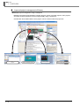
Improved project management efficiency
● Multiple project management using a workspace
Multiple project data (programmable controller projects, motion controller projects, GOT projects,
and robot controller projects) can be managed totally using a workspace.
Created date and modified date of each project can be confirmed with the project list.
Programmable controller
project
1-4
Motion controller project
GOT project
Robot controller project
1.2 Features
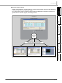
Parameters, such as I/O assignment and network parameters, which require consistencies can be
set without opening related projects of each engineering software (GX Works2, MT Developer2,
and GT Designer3).
Parameters set to the project on CPU No. 1 can be utilized for the project on CPU No. 2 when
configuring multiple CPU system.
2
SCREEN
CONFIGURATION
For the parameter setting function, refer to the following chapter.
OVERVIEW
1
Simplified parameter settings
Chapter 3
< I/O assignment/Network parameter >
OPERATING PROCEDURE
OF MELSOFT NAVIGATOR
3
Parameters are set
by reflecting them
to the project.
USING SYSTEM
LABELS
4
CREATING SYSTEM
BACKUP DATA
5
< Multiple CPU parameter >
QCPU
(CPU No. 1)
6
USING PROGRAM
JUMP FUNCTION
■
Multiple CPU parameter of CPU No. 1
Motion controller (CPU No. 2)
Utilize
Multiple CPU parameter of CPU
No. 2 and other CPUs
1-5
iQ Works
1 OVERVIEW
■
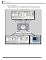
Improved programming efficiency using system labels
System labels are labels that can be used in any project within the workspace (within the
equipment configured in the network configuration diagram or module configuration diagram).
Programming (drawing) efficiency is improved by opening devices of programmable controller
projects and motion controller projects as system labels, and sharing them with multiple projects.
As the device assignment settings are changed in batch, device assignment changes are not
necessary on other projects or graphics.
For using system labels, refer to the following chapter.
Chapter 4
< Workspace >
System labels
(Valid within workspace)
< Programmable controller project >
Global labels
(Valid within project)
[Program (MAIN)]
Local labels
(Valid within program)
< Programmable controller project >
Global labels
(Valid within project)
[Program (SUB)]
Local labels
(Valid within program)
[Program (MAIN)]
Local labels
(Valid within program)
< GOT project >
< Motion controller project >
Labels
(Valid within project)
To use system labels in iQ Platform supporting engineering environment MELSOFT iQ Works,
utilize system labels registered in MELSOFT Navigator from projects (Top-down design method),
or register global labels defined in projects as system labels (Bottom-up design method).
1-6
1.2 Features
Design system labels for accessing GOT or communicating between equipment after designing
network configuration in the upstream design.
In top-down design method, register system labels using MELSOFT Navigator, import them to
global labels of controller projects, and assign devices.
OVERVIEW
1
● Top-down design method
2
SCREEN
CONFIGURATION
< Workspace >
MELSOFT Navigator
OPERATING PROCEDURE
OF MELSOFT NAVIGATOR
3
Register system labels
4
USING SYSTEM
LABELS
System label
database
Use system labels in controller projects
CREATING SYSTEM
BACKUP DATA
5
Programmable controller project
Motion controller project
USING PROGRAM
JUMP FUNCTION
6
GOT project
1-7
iQ Works
1 OVERVIEW
● Bottom-up design method
Design system labels for accessing GOT by using global labels which are registered in controller
projects as system labels, for a such case when configuring system by utilizing existing projects.
< Workspace >
Programmable controller project
Motion controller project
Register global labels as system labels
MELSOFT Navigator
System label
database
Utilize system labels
Programmable controller project
1-8
Motion controller project
GOT project
1.2 Features
1
Simplified data backup operation
OVERVIEW
All controller projects in the workspace can be read and saved in batch without activating
respective engineering software (GX Works2, MT Developer2, and GT Designer3).
For the batch read function, refer to the following chapter.
Chapter 5
Programmable controller
project
SCREEN
CONFIGURATION
2
MELSECNET/H
3
OPERATING PROCEDURE
OF MELSOFT NAVIGATOR
Programmable controller
project
Motion controller project
GOT project
USING SYSTEM
LABELS
4
CREATING SYSTEM
BACKUP DATA
5
Create backup data in batch
6
USING PROGRAM
JUMP FUNCTION
■
MELSOFT Navigator
1-9
iQ Works
1 OVERVIEW
■
Improved programming efficiency by linking with motion controller programs
A motion controller program, which corresponds to the motion dedicated programmable controller
instruction selected in the sequence program, can be activated by a simple mouse operation. This
function significantly improves programming efficiency.
For the program jump function, refer to the following chapter.
Chapter 6
Activate the programmable
controller project
The motion controller project
corresponds to the selected
motion dedicated programmable
controller instruction is activated.
1 - 10
SCREEN CONFIGURATION
2
SCREEN
CONFIGURATION
2
OVERVIEW
1
This chapter explains the screen configuration of MELSOFT Navigator.
OPERATING PROCEDURE
OF MELSOFT NAVIGATOR
3
4
USING SYSTEM
LABELS
Screen Configuration . . . . . . . . . . . . . . . . . . . . . . . . . . . . . . . . 2-2
CREATING SYSTEM
BACKUP DATA
5
6
USING PROGRAM
JUMP FUNCTION
2.1
2-1
iQ Works
2 SCREEN CONFIGURATION
2.1
Screen Configuration
The following explains the screen configuration.
Screen display
Module Configuration
window
Network Configuration
window
Title bar
Menu bar
Toolbar
Workspace
window
Module List
window
Configuration window
Bird's-eye
window
Input Detailed
Configuration
Information
window
Status bar
Result of Power Supply Capacity and I/O Points Check window
Output window
Task List window
Display contents
Name
2-2
Description
Title bar
Displays a title of product name, workspace path, and active window.
Menu bar
Displays items of the basic menu.
Toolbar
Displays tool buttons for functions executed frequently.
Workspace window
Displays objects managed in a workspace in tree format.
Bird’s-eye window
Displays a bird’s-eye view of the Network Configuration window.
Module Configuration window
Set details of graphical Q series/L series/FX series module configurations which are
allocated in the network configuration diagram.
Network Configuration window
Set graphical network configuration.
Configuration window
Set configurations and display them graphically.
Module List window
Displays modules used in Q series/L series/FX series in list form.
Input Detailed Configuration
Information window
Set I/O assignment and network parameters required in MELSOFT Navigator.
Output window
Displays messages and log outputs being processed in the parameter reflection process in
list form.
Task List window
Displays a result of system configuration check, power supply capacity and I/O points
check or system label consistency check in list form.
Result of Power Supply Capacity
and I/O Points Check window
Displays a result of power supply capacity and I/O points check.
Status bar
Displays information about the selected project.
CREATING SYSTEM
BACKUP DATA
USING SYSTEM
LABELS
OPERATING PROCEDURE
OF MELSOFT NAVIGATOR
SCREEN
CONFIGURATION
Help information of MELSOFT iQ Works can be displayed by pressing the
USING PROGRAM
JUMP FUNCTION
key.
OVERVIEW
2.1 Screen Configuration
1
2
3
4
5
6
2-3
iQ Works
2 SCREEN CONFIGURATION
MEMO
2-4
OPERATING PROCEDURE
OF MELSOFT NAVIGATOR
This chapter explains the methods for creating workspaces and system configurations using MELSOFT
Navigator.
2
SCREEN
CONFIGURATION
3
OVERVIEW
1
OPERATING PROCEDURE
OF MELSOFT NAVIGATOR
3
4
USING SYSTEM
LABELS
Procedure of MELSOFT Navigator from Start to End . . . . . . 3-2
Starting MELSOFT Navigator . . . . . . . . . . . . . . . . . . . . . . . . . . 3-3
Creating Workspaces . . . . . . . . . . . . . . . . . . . . . . . . . . . . . . . . 3-4
Creating System Configuration Diagram . . . . . . . . . . . . . . . . 3-8
Creating Projects. . . . . . . . . . . . . . . . . . . . . . . . . . . . . . . . . . . 3-30
Setting Parameters . . . . . . . . . . . . . . . . . . . . . . . . . . . . . . . . . 3-38
Checking System Configuration . . . . . . . . . . . . . . . . . . . . . . 3-47
Editing Projects . . . . . . . . . . . . . . . . . . . . . . . . . . . . . . . . . . . . 3-49
Reading/Writing/Verifying Controller Data . . . . . . . . . . . . . . 3-53
Saving Workspaces. . . . . . . . . . . . . . . . . . . . . . . . . . . . . . . . 3-56
Printing Workspaces . . . . . . . . . . . . . . . . . . . . . . . . . . . . . . . 3-58
Closing Workspaces . . . . . . . . . . . . . . . . . . . . . . . . . . . . . . . 3-59
Exiting MELSOFT Navigator. . . . . . . . . . . . . . . . . . . . . . . . . 3-60
CREATING SYSTEM
BACKUP DATA
5
6
USING PROGRAM
JUMP FUNCTION
3.1
3.2
3.3
3.4
3.5
3.6
3.7
3.8
3.9
3.10
3.11
3.12
3.13
3-1
iQ Works
3 OPERATING PROCEDURE OF MELSOFT NAVIGATOR
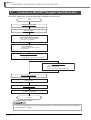
3.1
Procedure of MELSOFT Navigator from Start to End
This section explains the procedure of MELSOFT Navigator from start to end.
Start
Start MELSOFT Navigator
Create a workspace
Create a system configuration diagram
Create module configuration diagrams
Create a network configuration diagram
Create a CC-Link configuration
Create projects
Create new projects
Allocate the projects to the controllers
Set parameters
Check the system configuration
Check the system configuration
Check the power supply capacity and I/O points*1
Edit the created projects
Edit the projects
Utilize an existing project
Perform controller data read/write/verification
Save the created workspace
Print the project
Close the workspace
Exit MELSOFT Navigator
Complete
*1 : Not supported by FXCPU.
Do not change the storage location and names of folders/files of a created workspace/project using the application
such as Windows® Explorer.
3-2
3.2 Starting MELSOFT Navigator
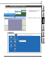
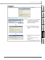
Starting MELSOFT Navigator
This section explains a method for starting MELSOFT Navigator.
1.
Start MELSOFT Navigator from
Windows [Start] menu.
2.
MELSOFT Navigator is activated.
2
SCREEN
CONFIGURATION
Select
OVERVIEW
3.2
1
OPERATING PROCEDURE
OF MELSOFT NAVIGATOR
3
USING SYSTEM
LABELS
4
icon on the desktop can also start MELSOFT Navigator.
6
USING PROGRAM
JUMP FUNCTION
●Double-clicking the
CREATING SYSTEM
BACKUP DATA
5
Double-click the MELSOFT
Navigator icon.
3-3
iQ Works
3 OPERATING PROCEDURE OF MELSOFT NAVIGATOR
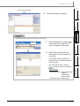
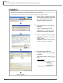
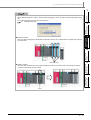
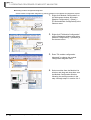
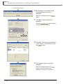
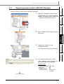
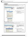
3.3
Creating Workspaces
This section explains a method for creating a new workspace.
Select
1.
Select [Workspace] ⇒ [New] (
menu bar to display the "New
(Workspace)" dialog box.
2.
Set "Save Folder Path", "Workspace
Name", and "Title" for the new
workspace.
) in the
After setting the items, click the
button.
Setting example
• Save Folder Path : C:\Documents and
Settings\
Administrator\
My Documents
• Workspace Name: Sample_WS
• Title (option)
: Sample Data
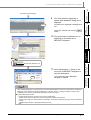
3.
The "Choose a Default Configuration"
dialog box is displayed.
Select "Create Module Configuration" and
click the
button.
Setting example
• Configuration
4.
: Q Series
Module Configuration
The message shown on the left is
displayed.
Read the message and click the
button.
(To the next page)
3-4
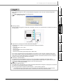
3.3 Creating Workspaces
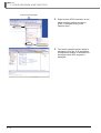
1
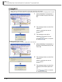
(From the previous page)
The new workspace is created.
OVERVIEW
5.
SCREEN
CONFIGURATION
2
1.
Select [Workspace] ⇒ [Open] (
in the menu bar to display the
"Open (Workspace)" dialog box.
2.
Select "Save Folder Path" and
"Workspace" for the workspace to
be opened.
)
The workspace folder copied by the
application such as Windows® Explorer
can be selected.
After selecting the items, click the
button to open the workspace.
Setting example
• Save Folder Path : C:\Documents and
Settings\
Administrator\
My Documents
• Workspace Name: Sample_WS
3-5
4
USING SYSTEM
LABELS
Select
5
CREATING SYSTEM
BACKUP DATA
Open an existing workspace by following the procedure below.
6
USING PROGRAM
JUMP FUNCTION
● Opening existing workspaces
OPERATING PROCEDURE
OF MELSOFT NAVIGATOR
3
iQ Works
3 OPERATING PROCEDURE OF MELSOFT NAVIGATOR
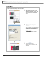
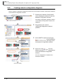
● Creating workspaces for motion system using templates
Workspaces for motion system can be created from templates consist of a combination of programmable controller
CPU and motion controller, which are used for multiple CPU system configuration.
The following shows the procedure to create a workspace for motion system using a template.
Select
1.
Select [Tools] ⇒ [Motion Dedicated
Device Setting Support] in the menu
bar to display the "Select Motion
System Template" dialog box.
2.
The message shown on the left is
displayed.
Read the message and click the
button to display the "Select
Motion System Template" dialog box.
3.
Select a workspace name in "Select
Template Workspace", and click the
button.
The "Motion Dedicated Device Setting
Support" dialog box is displayed.
Click
4.
Set "Save folder path" and
"Workspace name" for the template
workspace.
After setting the items, click the
button.
Setting example
• Save Folder Path : C:\Documents and
Settings\
Administrator\
My Documents
• Workspace Name: WS_tmp1
(To the next page)
3-6
CREATING SYSTEM
BACKUP DATA
USING SYSTEM
LABELS
OPERATING PROCEDURE
OF MELSOFT NAVIGATOR
SCREEN
CONFIGURATION
5.
USING PROGRAM
JUMP FUNCTION
The workspace for motion system is
displayed.
3-7
OVERVIEW
3.3 Creating Workspaces
1
(From the previous page)
2
3
4
5
6
iQ Works
3 OPERATING PROCEDURE OF MELSOFT NAVIGATOR
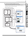
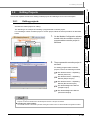
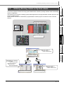
3.4
Creating System Configuration Diagram
This section explains a method for creating a system configuration diagram.
Created module configuration diagrams are reflected to the network configuration diagram.
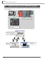
3.4.1
System configuration to be created
Create the following system configuration diagram.
< Configuration diagram A >
Module configuration diagrams
(Empty)
(Empty)
(Empty)
QCPU
(Q06UDHCPU)
Input module
(QX40)
Network module
(QJ71LP21-25)
Power supply
(Q62P)
Base unit (Q35B)
Station No. 1: Control station
MELSECNET/H
Station No. 2: Normal station
< Configuration diagram B >
GOT
(GOT1000)
(Empty)
(Empty)
(Empty)
(Empty)
Network module
(QJ71LP21-25)
Master module
(QJ61BT11N)
I/O module
(QH42P)
QCPU
(Q06UDHCPU)
Motion CPU
(Q173DCPU)
Power supply
(Q64P)
Base unit (Q38DB)
<CC-Link configuration A>
Remote I/O
station
(AJ65SBTB1-8D)
Remote device
station
(AJ65BT-64DAV)
Remote device
station
(FR-A720-0.4K)
Network configuration diagram
CC-Link configuration
3-8
3.4.1 System configuration to be created
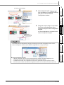
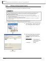
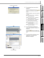
3.4 Creating System Configuration Diagram
Create module configuration diagrams by placing modules on the Module Configuration window.
Right-click "Q Module Configuration"
on the Workspace window, and select
[Module Configuration] ⇒ [Rename] in
the shortcut menu.
2
SCREEN
CONFIGURATION
1.
OVERVIEW
1
Creating module configuration diagrams
Select
2.
OPERATING PROCEDURE
OF MELSOFT NAVIGATOR
3
Enter "Configuration diagram A" to
change the module configuration
diagram name.
3.
Drag & drop
Select the base unit (
) from the
Module List window, and drag and drop
it onto the Module Configuration
window.
USING SYSTEM
LABELS
4
4.
Select the power supply module
(
) from the Module List window,
and drag and drop it onto the base unit.
Drag & drop
CREATING SYSTEM
BACKUP DATA
5
6
5.
Select modules from the Module List
window, and drag and drop them onto
the base unit following the same
procedure in the step 4, and complete
the creation of "Configuration diagram
A".
(To the next page)
3.4.2 Creating module configuration diagrams
3-9
USING PROGRAM
JUMP FUNCTION
3.4.2
iQ Works
3 OPERATING PROCEDURE OF MELSOFT NAVIGATOR
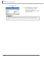
(From the previous page)
6.
Select [Workspace] ⇒ [System
Configuration] ⇒ [New] ⇒ [Q Series
Module Configuration], and create a
new module configuration diagram.
7.
Change the module configuration name
to "Configuration diagram B" following
the same procedure in the step 1 and
step 2.
8.
Select modules from the Module List
window, and drag and drop them onto
the base unit following the same
procedure in the step 3 and step 4.
9.
Select the GOT unit (
) from
the Module List window, and drag and
drop it onto the Module Configuration
window.
Select
Drag & drop
10. The message shown on the left is
displayed.
Read the message and click the
button.
(To the next page)
3 - 10
3.4.2 Creating module configuration diagrams
3.4 Creating System Configuration Diagram
1
11. Select Serial Cable (
2
SCREEN
CONFIGURATION
) from
the Module List window, and drag and
drop it onto the connection port of the
GOT unit.
OVERVIEW
(From the previous page)
12. Drag and drop the edge of connection
line to the connection port of the
connection target CPU module.
The GOT unit is connected to the CPU
module.
3
OPERATING PROCEDURE
OF MELSOFT NAVIGATOR
Drag & drop
4
USING SYSTEM
LABELS
Drag & drop
CREATING SYSTEM
BACKUP DATA
5
USING PROGRAM
JUMP FUNCTION
6
3.4.2 Creating module configuration diagrams
3 - 11
iQ Works
3 OPERATING PROCEDURE OF MELSOFT NAVIGATOR
● Mounting modules
• When a module is dragged onto the base unit, the mountable area of the base unit is displayed in light green as
shown below.
Mountable slots
• If a module is not mounted properly, the whole module is displayed in pink as shown below.
● Connection lines
When a connection line is dragged and dropped onto the Module Configuration window, the connectable ports of
each controller are displayed as shown below.
Connectable ports
Drag & drop
● Connection points of GOT unit
By setting parameters on the Input Detailed Configuration Information window, I/F type and number of
connectable points of GOT unit can be changed.
3 - 12
3.4.2 Creating module configuration diagrams
3.4 Creating System Configuration Diagram
■
1
Creating module configuration diagrams for L series
OVERVIEW
For L series, create module configuration diagrams refer to this section.
Basically, L series module configurations can be created in a similar way to Q series.
For operations that differ from Q series, refer to the Point in this section.
● System configuration to be created
2
Module configuration diagrams
END cover (L6EC)
3
OPERATING PROCEDURE
OF MELSOFT NAVIGATOR
LCPU
(L02CPU)
Input module
(LX40C6)
<L module configuration diagram A>
Power supply
(L61P)
SCREEN
CONFIGURATION
Create the following system configuration.
IP address :192.168.3.38
4
Ethernet (Network No.1)
USING SYSTEM
LABELS
END cover (L6EC)
5
CREATING SYSTEM
BACKUP DATA
Input module
(LX40C6)
LCPU
(L02CPU)
RS-232 adaptor
(L6ADP-R2)
Power supply
(L61P)
<L module configuration diagram B>
IP address :192.168.3.39
GOT
(GOT1000)
6
USING PROGRAM
JUMP FUNCTION
Network configuration diagram
3.4.2 Creating module configuration diagrams
3 - 13
iQ Works
3 OPERATING PROCEDURE OF MELSOFT NAVIGATOR
● Creating module configuration diagrams
Create module configuration diagrams by placing modules on the Module Configuration window.
1.
Right-click "Module Configuration" on
the Workspace window, and select
[Module Configuration] ⇒ [New] ⇒
[L Series Module Configuration] in the
shortcut menu.
2.
Right-click "L Module Configuration "
on the Workspace window, and select
[Module Configuration] ⇒ [Rename] in
the shortcut menu.
3.
Enter "L module configuration diagram
A" to change the module configuration
diagram name.
4.
Select modules from the Module List
window, and drag and drop them onto
the Module Configuration window
following the same procedure in the
step 4 through step11 in section 3.4.2.
Select
Select
Drag & drop
3 - 14
3.4.2 Creating module configuration diagrams
3.4 Creating System Configuration Diagram
2
SCREEN
CONFIGURATION
● Creating L series module configurations
When creating workspaces, select "L Series Module Configuration" in the "Choose a Default Configuration" dialog
box.
For creating workspaces, refer to the following section.
3.3 Creating Workspaces
OVERVIEW
1
3
OPERATING PROCEDURE
OF MELSOFT NAVIGATOR
● Mounting modules
When a module is dragged onto the Module Configuration window, the mountable areas are displayed in light blue
as shown below.
USING SYSTEM
LABELS
4
● Deleting modules
When a module is deleted from the Module Configuration window, the modules next to the deleted module are
connected automatically as shown below.
CREATING SYSTEM
BACKUP DATA
5
Mountable areas
USING PROGRAM
JUMP FUNCTION
6
Delete
3.4.2 Creating module configuration diagrams
3 - 15
iQ Works
3 OPERATING PROCEDURE OF MELSOFT NAVIGATOR
● Mounting display module
Display module can be mounted on L series CPU modules.
Mount display module by following procedure below.
1.
Right click the controller on the
Module Configuration window, and
select [Property] in the shortcut
menu.
2.
The "Properties" dialog box is
displayed.
Select
Select "Installed" in the Display Module
tab and select the model name to be
mounted from "Select Model Name"
Setting example
• Select Model Name :L6DSPU
3.
Click the
button.
Display module is mounted on the
controller.
3 - 16
3.4.2 Creating module configuration diagrams
3.4 Creating System Configuration Diagram
1
Creating module configuration diagrams for FX series
For FX series, create module configuration diagrams refer to this section.
Basically, FX series module configurations can be created in a similar way to Q series.
For operations that differ from Q series, and for main units, special blocks, and special adapters that
can be used in FX series, refer to the Point in this section.
2
● System configuration to be created
SCREEN
CONFIGURATION
Create the following system configuration.
<FX Module configuration diagramA>
Module configuration diagram
Ethernet
special function block
3
OPERATING PROCEDURE
OF MELSOFT NAVIGATOR
FXCPU
(FX3UCPU)
OVERVIEW
■
IP address :192.168.3.38
4
USING SYSTEM
LABELS
Ethernet (Network No.1)
Ethernet
special function block
5
CREATING SYSTEM
BACKUP DATA
FXCPU
(FX3UCPU)
<FX Module configuration diagramB>
IP address :192.168.3.39
USING PROGRAM
JUMP FUNCTION
6
GOT
(GOT1000)
Network configuration diagram
3.4.2 Creating module configuration diagrams
3 - 17
iQ Works
3 OPERATING PROCEDURE OF MELSOFT NAVIGATOR
● Creating module configuration diagrams
Create module configuration diagrams by placing modules on the Module Configuration window.
1.
Right-click "Module Configuration" on
the Workspace window, and select
[Module Configuration] ⇒ [New] ⇒
[FX Series Module Configuration] in the
shortcut menu.
2.
Right-click "FX Module Configuration"
on the Workspace window, and select
[Module Configuration] ⇒ [Rename] in
the shortcut menu.
3.
Enter "FX module configuration
diagramA" to change the module
configuration diagram name.
4.
Select modules from the Module List
window, and drag and drop them onto
the Module Configuration window
following the same procedure in the
step 4 through step11 in section 3.4.2.
Select
Select
Drag & drop
3 - 18
3.4.2 Creating module configuration diagrams
3.4 Creating System Configuration Diagram
2
SCREEN
CONFIGURATION
● Creating FX series module configurations
When creating workspaces, select "FX Series Module Configuration" in the "Choose a Default Configuration"
dialog box.
For creating workspaces, refer to the following section.
3.3 Creating Workspaces
OVERVIEW
1
3
OPERATING PROCEDURE
OF MELSOFT NAVIGATOR
● Mounting modules
When a module is dragged onto the Module Configuration window, the mountable areas are displayed in light blue
as shown below.
USING SYSTEM
LABELS
4
Mountable area
5
CREATING SYSTEM
BACKUP DATA
● Supported CPU modules of FX series in MELSOFT Navigator
The following CPU modules of FX series are supported in MELSOFT Navigator.
• Main units
FX3S, FX3G, FX3GC, FX3U, FX3UC
• Special block
Ethernet special function block (FX-ENET series)
• Special adapter
Ethernet communication special adapter (FX3U-ENET-ADP)
For FX series, special blocks and special adapters are mounted to a main unit which combines power supply,
CPU, and I/O module. However, the following blocks and units can not be mounted: special blocks and special
units which do not contain related project or configuration software, and extension blocks which do not support a
function to check power supply capacity and I/O points.
● Parameters of special adapters
The parameters of special adapters can be set on the Input Detailed Configuration Information window.
The setting content is reflected to the parameter of a programmable controller project by performing parameter
reflection. For details of the parameter settings, refer to the following section.
Section 3.6 Setting Parameters
● Displaying module list window
The model name of special blocks of FX series compatible with MELSOFT Navigator are displayed on the Module
List window when the related software are installed.
When using special blocks install the related software*1 of each module in advance.
*1: The related software of FX-ENET series may be downloaded from MITSUBISHI ELECTRIC FA Global Website.
For the method of obtaining the related software, contact the store where you purchased the product.
3.4.2 Creating module configuration diagrams
3 - 19
USING PROGRAM
JUMP FUNCTION
6
iQ Works
3 OPERATING PROCEDURE OF MELSOFT NAVIGATOR
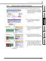
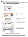
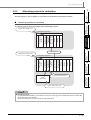
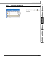
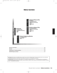
3.4.3
Creating network configuration diagrams
Create a network configuration diagram by placing and connecting the module configuration diagrams
on the Network Configuration window.
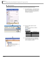
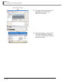
1.
Double click
Double-click "Network Configuration"
on the Workspace window to open the
Network Configuration window.
All module configuration diagrams created
on the Module Configuration windows are
displayed.
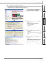
2.
Drag and drop the module
configuration diagrams to desired
positions.
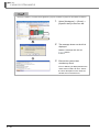
3.
Select MNET/H (Optical Loop Type)
(
) from the Module
List window, and drag and drop it onto
the Network Configuration window.
4.
Select CC-Link (
) from the
Module List window, and drag and drop
it onto the Network Configuration
window.
Drag & drop
Drag & drop
Drag & drop
CC-Link configuration is added on the
Workspace window.
(To the next page)
3 - 20
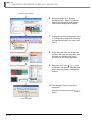
3.4.3 Creating network configuration diagrams
3.4 Creating System Configuration Diagram
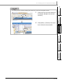
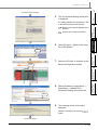
5.
Select Network Cable (
)
from the Module List window, and drag
and drop it onto the Network
Configuration window.
2
SCREEN
CONFIGURATION
Drag & drop
OVERVIEW
1
(From the previous page)
Drag and drop the edge of connection
line to the connection point of the
connection target module configuration
diagram.
CC-Link configuration is connected to the
module configuration diagram.
3
OPERATING PROCEDURE
OF MELSOFT NAVIGATOR
6.
4
USING SYSTEM
LABELS
Drag & drop
● Adding Ethernet configuration
When adding Ethernet configuration by dragging and dropping from Module Configuration window onto the
Network Configuration window, select an Ethernet configuration from "Component Device"
CREATING SYSTEM
BACKUP DATA
5
● Network Configuration window
• A Module Configuration window opens by double-clicking the module configuration diagram/CC-Link
configuration on the Network Configuration window/CC-Link configuration window.
For Ethernet/CC IE Field, each configuration window can be opened with the same operation as above.
• The whole system created on the Network Configuration window can be reviewed on the Bird’s-eye window.
3.4.3 Creating network configuration diagrams
3 - 21
USING PROGRAM
JUMP FUNCTION
6
Drag & drop
iQ Works
3 OPERATING PROCEDURE OF MELSOFT NAVIGATOR
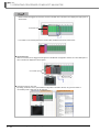
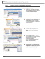
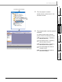
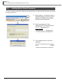
3.4.4
Creating CC-Link configuration diagrams
Create a configuration by placing modules on the CC-Link Configuration window.
1.
Double-click "CC-Link Configuration"
on the Workspace window to open the
CC-Link Configuration window.
2.
Right-click "CC-Link Configuration" on
the Workspace window, and select
[CC-Link Configuration] ⇒ [Rename] in
the shortcut menu.
3.
Enter "CC-Link configuration A" to
change the CC-Link configuration
name.
4.
Select AJ65SBTB1-8D (
)
from the Module List window, and drag
and drop it onto the CC-Link
Configuration window.
Double click
Select
Drag & drop
CC-Link configuration is added on the
Module configuration window.
5.
3 - 22
3.4.4 Creating CC-Link configuration diagrams
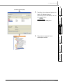
Select modules to be connected from
the Module List window, and drag and
drop them onto the CC-Link
Configuration window following the
same procedure in the step 4.
3.4 Creating System Configuration Diagram
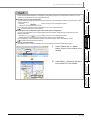
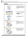
● Verifying CC-Link configuration against the actual system configuration
The CC-Link configuration can be verified against the actual system configuration by performing one of the
following operations.
2.
Select [Edit] ⇒ [Delete] in the menu
bar to delete CC-Link module.
Select
4
USING SYSTEM
LABELS
Select
Select "Station No." or "Model
Name" of the CC-Link module to be
deleted.
5
CREATING SYSTEM
BACKUP DATA
● Deleting CC-Link modules
The following shows a method for deleting CC-Link modules from CC-Link Configuration window.
OPERATING PROCEDURE
OF MELSOFT NAVIGATOR
3
• Click the
button on the CC-Link Configuration window.
• Select [Online] ⇒ [Verification of the Configuration with the Connected Module].
For the verification of the configuration with the connected modules, refer to the following manual.
iQ Sensor Solution Reference Manual
1.
2
SCREEN
CONFIGURATION
● Module display on configuration window
Check that the network modules on the Module Configuration window are connected to the network. If not, the
modules are not displayed on the configuration window.
● Detecting actual system configuration
The actual system configuration can be reflected to the CC-Link Configuration window by performing one of the
following operations.
• Click the
button on the CC-Link Configuration window.
• Select [Online] ⇒ [Detect Now].
For the automatic detection of connected devices, refer to the following manual.
iQ Sensor Solution Reference Manual
OVERVIEW
1
USING PROGRAM
JUMP FUNCTION
6
3.4.4 Creating CC-Link configuration diagrams
3 - 23
iQ Works
3 OPERATING PROCEDURE OF MELSOFT NAVIGATOR
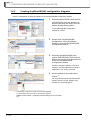
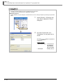
3.4.5
Creating AnyWireASLINK configuration diagrams
Create a configuration by placing modules on the AnyWireASLINK Configuration window.
1.
Select AnyWireASLINK master module
(QJ51AW12AL) from the Module List
window, and drag and drop it onto the
Module Configuration window.
The AnyWireASLINK configuration
diagram is created.
Drag & drop
2.
Double-click "AnyWireASLINK
Configuration" on the Workspace
window to open the AnyWireASLINK
Configuration window.
3.
Select the AnyWireASLINK slave
module (B281PB-02U-CC20) from the
Module List window, and drag and drop
it onto the AnyWireASLINK
Configuration window.
Double click
Drag & drop
The slave module is added on the "list of
modules", and the added slave module is
displayed on the "device map area".
4.
Set the address to the added slave
module.*1
For the general-purpose AnyWireASLINK
module, set the I/O type, address, and
number of occupied I/O points.
*1: The address of the slave module can be set automatically.
For the address auto-input, refer to the following manual.
GX Works2 Version 1 Operating Manual (Intelligent Function Module)
3 - 24
3.4.5 Creating AnyWireASLINK configuration diagrams
3.4 Creating System Configuration Diagram
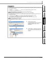
● Deleting AnyWireASLINK slave modules
The following shows a method for deleting AnyWireASLINK slave modules from AnyWireASLINK Configuration
window.
1.
Select
Select [Edit] ⇒ [Delete] in the menu
bar to delete AnyWireASLINK slave
module.
3
4
5
CREATING SYSTEM
BACKUP DATA
2.
Select the row of the
AnyWireASLINK slave module to be
deleted. (Multiple rows can be
selected.)
SCREEN
CONFIGURATION
• Click the
button on the AnyWireASLINK Configuration window.
• Select [Online] ⇒ [Verification of the Configuration with the Connected Module].
For the verification of the configuration with the connected modules, refer to the following manual.
iQ Sensor Solution Reference Manual
OPERATING PROCEDURE
OF MELSOFT NAVIGATOR
● Verifying AnyWireASLINK configuration against the actual system configuration
The AnyWireASLINK configuration can be verified against the actual system configuration by performing one of
the following operations.
2
USING SYSTEM
LABELS
● Detecting actual system configuration
The actual system configuration can be reflected to the AnyWireASLINK Configuration window by performing one
of the following operations.
• Click the
button on the AnyWireASLINK Configuration window.
• Select [Online] ⇒ [Detect Now].
For the automatic detection of connected devices, refer to the following manual.
iQ Sensor Solution Reference Manual
OVERVIEW
1
Select
USING PROGRAM
JUMP FUNCTION
6
3.4.5 Creating AnyWireASLINK configuration diagrams
3 - 25
iQ Works
3 OPERATING PROCEDURE OF MELSOFT NAVIGATOR
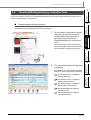
3.4.6
Creating Ethernet configuration diagrams
Create a configuration by placing modules on the Ethernet Configuration window.
1.
Right-click "Ethernet Configuration" on
the Workspace window, and select
[Ethernet Configuration] ⇒ [Rename] in
the shortcut menu.
2.
Enter "Ethernet configuration A" to
change the Ethernet configuration
name.
3.
Select an Ethernet built-in CPU to be
set as an own station and IP address of
Ethernet module.
4.
Double-click "Ethernet Configuration"
on the Workspace window to open the
Ethernet Configuration window.
5.
Select an Ethernet device*1 from the
Module List window, and drag and drop
it onto the Ethernet Configuration
window.
Select
Double click
Drag & drop
*1:
3 - 26
For the parameter processing of Ethernet devices, refer to the following manual.
iQ Sensor Solution Reference Manual
3.4.6 Creating Ethernet configuration diagrams
3.4 Creating System Configuration Diagram
iQ Sensor Solution Reference Manual
● Reflecting communication settings of Ethernet devices
The communication settings of Ethernet devices can be reflected by performing the following operation.
• Select [Online] ⇒ [Communication Setting Reflection of Ethernet Device]
For the Communication Setting Reflection of Ethernet Device function, refer to the following manual.
2.
Select [Edit] ⇒ [Delete] in the menu
bar to delete Ethernet device.
5
CREATING SYSTEM
BACKUP DATA
Select
4
USING SYSTEM
LABELS
Select
Select the row of the Ethernet
device to be deleted. (Multiple rows
can be selected.)
OPERATING PROCEDURE
OF MELSOFT NAVIGATOR
3
iQ Sensor Solution Reference Manual
● Deleting Ethernet devices
The following shows a method for deleting Ethernet devices from Ethernet Configuration window.
1.
2
SCREEN
CONFIGURATION
● Module display on the configuration window
Check that the network modules on the Module Configuration window are connected to the network. If not, the
modules are not displayed on the configuration window.
● Detecting actual system configuration
The actual system configuration can be reflected to the Ethernet Configuration window by performing one of the
following operations.
• Click the
button on the Ethernet Configuration window.
• Select [Online] ⇒ [Detect Now]
For the automatic detection of connected devices, refer to the following manual.
OVERVIEW
1
USING PROGRAM
JUMP FUNCTION
6
3.4.6 Creating Ethernet configuration diagrams
3 - 27
iQ Works
3 OPERATING PROCEDURE OF MELSOFT NAVIGATOR
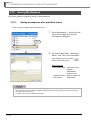
3.4.7
Creating CC IE Field configuration diagrams
Create a configuration by placing modules on the CC IE Field Configuration window.
1.
CC IE Field configuration diagram*1 is
created.
Double click
2.
Right-click "CC IE Field Configuration"
on the Workspace window, and select
[CC IE Field Configuration] ⇒
[Rename] in the shortcut menu .
3.
Enter "CC IE Field configuration A" to
change the CC IE Field configuration
name.
4.
Select a slave station*1 from the
Module List window, and drag and drop
it onto the CC IE Field Configuration
window.
Select
Drag & drop
*1:
Double-click "CC IE Field
Configuration" on the Workspace
window to open the CC IE Field
Configuration window.
For the parameter processing of slave station, refer to the following manual.
GX Works2 Version 1 Operating Manual (Common)
● Module display on configuration window
Check that the network modules on the Module Configuration window are connected to the network. If not, the
modules are not displayed on the configuration window.
3 - 28
3.4.7 Creating CC IE Field configuration diagrams
3.4 Creating System Configuration Diagram
1.
Select
Select [Edit] ⇒ [Delete] in the menu
bar to delete the slave station.
2
3
OPERATING PROCEDURE
OF MELSOFT NAVIGATOR
2.
Select the row of the slave station to
be deleted. (Multiple rows can be
selected.)
SCREEN
CONFIGURATION
● Deleting slave stations of CC IE Field
The following shows a method for deleting slave stations from CC IE Field Configuration window.
OVERVIEW
1
Select
USING SYSTEM
LABELS
4
CREATING SYSTEM
BACKUP DATA
5
USING PROGRAM
JUMP FUNCTION
6
3.4.7 Creating CC IE Field configuration diagrams
3 - 29
iQ Works
3 OPERATING PROCEDURE OF MELSOFT NAVIGATOR
3.5
Creating Projects
This section explains the methods for creating project data (programmable controller projects, motion
controller projects, GOT projects).
3.5.1
■
Creating new projects
Programmable controller projects
Create a new programmable controller project.
Select
1.
Select [Project] ⇒ [New] ⇒ [GX
Works2 Project] in the menu bar to
display the "New (GX Works2 Project)"
dialog box.
2.
Set "Project Name", "Title", "Project
Type", "PLC Series", "PLC Type", and
"Language" for the new project.
After setting the items, click the
button.
Setting example
• Project Name : GXW2_Pro1
• Title (option) : Sample Data
• Project Type : Simple Project
• Use Labels
: Yes
• PLC Series : QCPU (Q mode)
• PLC Type
: Q06UDH
• Language
: Ladder
(To the next page)
3 - 30
3.5.1 Creating new projects
3.5 Creating Projects
1
3.
The new project is created.
2
SCREEN
CONFIGURATION
Double-click the created project on the
Workspace window.
OVERVIEW
(From the previous page)
Double click
GX Works2 Version 1 Operating
Manual (Common)
GX Works2 Version 1 Operating
Manual (Simple Project)
GX Works2 Version 1 Operating
Manual (Structured Project)
GX Works2 Beginner's Manual
(Simple Project)
GX Works2 Beginner's Manual
(Structured Project)
4
USING SYSTEM
LABELS
For editing programmable controller
projects, refer to the following manuals.
5
CREATING SYSTEM
BACKUP DATA
The programmable controller project is
activated.
6
USING PROGRAM
JUMP FUNCTION
4.
OPERATING PROCEDURE
OF MELSOFT NAVIGATOR
3
3.5.1 Creating new projects
3 - 31
iQ Works
3 OPERATING PROCEDURE OF MELSOFT NAVIGATOR
■
Motion controller projects
Create a new motion controller project.
1.
Select [Project] ⇒ [New] ⇒ [MT
Developer2 Project] in the menu bar to
display the "New (MT Developer2
Project)" dialog box.
2.
Set "Project Name", "Title", "CPU
Type", and "OS Type" for the new
project.
Select
After setting the items, click the
button.
Setting example
• Project Name : MTD2_Pro1
• Title (option) : Sample Data
• CPU Type
: Q173D
• OS Type
: SW8-SV13QB
3.
The new project is created.
Double-click the created project on the
Workspace window.
Double click
4.
The motion controller project is
activated.
For editing motion controller projects, refer
to the Help function of MT Developer2.
3 - 32
3.5.1 Creating new projects
3.5 Creating Projects
■
1
GOT projects
Set "Series", "GOT Type", and "Project
Name".
After setting the item, click the
button.
Setting example
• Series
: GOT1000
• GOT Type
: GT10**-Q (320 x 240)
• Project Name : GOT_Pro1
3.
The new project is created.
Double-click the created project on the
Workspace window.
SCREEN
CONFIGURATION
2.
2
3
OPERATING PROCEDURE
OF MELSOFT NAVIGATOR
Select
Select [Project] ⇒ [New] ⇒ [GT
Designer3 Project] in the menu bar to
display the "New (GT Designer3
Project)" dialog box.
4
USING SYSTEM
LABELS
1.
OVERVIEW
Create a new GOT project.
5
CREATING SYSTEM
BACKUP DATA
Double click
4.
The GOT project is activated.
For editing GOT projects, refer to the
following manuals.
GT Designer3 Version 1 Screen Design
Manual (Fundamentals)
GT Designer3 Version 1 Screen Design
Manual (Functions)
GT Designer3 (GOT2000) Screen Design
Manual
GT Simulator3 Version 1 Operating
Manual
GT SoftGOT1000 Version 3 Operating
Manual
GT SoftGOT2000 Version1 Operating
Manual
3.5.1 Creating new projects
3 - 33
USING PROGRAM
JUMP FUNCTION
6
iQ Works
3 OPERATING PROCEDURE OF MELSOFT NAVIGATOR
● Copying projects
The following shows a method for copying a project created in the workspace to create a new project.
1.
Right-click the project name on the
Workspace window, and select [Add
Project Copy] in the shortcut menu
to display the "Add Project Copy"
dialog box.
2.
Enter a project name for the copied
project, and click the
button.
Setting example
• Project Name: GXW2_Pro2
3.
The copied project is displayed in
the Workspace window.
● Changing project names
The following shows a method for changing a project name of an existing project.
•
Right click
Right-click the project name on the
Workspace window, and select
[Change Project Name] in the
shortcut menu to change the project
name.
Select
● Deleting projects
The following shows a method for deleting a project. Once a project is deleted, it cannot be restored again.
•
Right click
Select
3 - 34
3.5.1 Creating new projects
Right-click the project name on the
Workspace window, and select
[Delete Project] in the shortcut
menu to delete the project.
3.5 Creating Projects
3.5.2
1
Allocating projects to controllers
■
OVERVIEW
Allocate projects in the workspace to controllers on the Module Configuration windows.
Allocating projects to controllers
2
SCREEN
CONFIGURATION
The following figure shows controllers with the allocated projects.
Project name: GXW2_Pro1
< Configuration diagram A >
OPERATING PROCEDURE
OF MELSOFT NAVIGATOR
(Empty)
(Empty)
3
(Empty)
QCPU
(Q06UDHCPU)
Input module
(QX40)
Network module
(QJ71LP21-25)
Power supply
(Q62P)
Base unit (Q35B)
4
USING SYSTEM
LABELS
MELSECNET/H
Project name: GXW2_Pro2
< Configuration diagram B >
5
CREATING SYSTEM
BACKUP DATA
(Empty)
(Empty)
(Empty)
(Empty)
Master module
(QJ61BT11N)
QCPU
(Q06UDHCPU)
Motion CPU
(Q173DCPU)
I/O module
(QH42P)
Network module
(QJ71LP21-25)
Power supply
(Q64P)
Base unit (Q38DB)
6
Project name: MTD2_Pro1
USING PROGRAM
JUMP FUNCTION
GOT
(GOT1000)
Project name: GOT_Pro1
● Allocating projects
A project cannot be allocated to a controller if a PLC type or a CPU type of the created project does not match with
the module name of the controller.
Check the module name of each controller and allocate projects.
3.5.2 Allocating projects to controllers
3 - 35
iQ Works
3 OPERATING PROCEDURE OF MELSOFT NAVIGATOR
■
Batch allocation
Allocate projects in the workspace to all controllers on the Module Configuration windows.
1.
Select [Workspace] ⇒ [Allocate Project
With The Controller] in the menu bar to
display the "Allocate Project With The
Controller" dialog box.
2.
Select a project name for each
controller.
After selecting the items, click the
button.
Select
Select
Click
Setting example
Module name
3.
3 - 36
3.5.2 Allocating projects to controllers
Project name
Q06UDHCPU
GXW2_Pro1: Sample Data
Q06UDHCPU
GXW2_Pro2: Sample Data
Q173DCPU
MTD2_Pro1: Sample Data
GT10**-Q
GOT_Pro1
The allocated projects are displayed
under the Module Configuration folder
on the Workspace window.
3.5 Creating Projects
■
1
Individual allocation
Right-click the controller on the Module
Configuration window, and select
[Allocate Project With The Controller] in
the shortcut menu to display the
"Allocate Project With The Controller"
dialog box.
Setting example
Module name
Q06UDHCPU
3.
Project name
GXW2_Pro1: Sample Data
The allocated project is displayed
under the Module Configuration folder
on the Workspace window.
4
USING SYSTEM
LABELS
Click
Select a project name for the selected
controller.
After selecting the item, click the
button.
5
CREATING SYSTEM
BACKUP DATA
2.
OPERATING PROCEDURE
OF MELSOFT NAVIGATOR
3
Select
Select
2
SCREEN
CONFIGURATION
1.
OVERVIEW
Allocate a project in the workspace to the controller selected on the Module Configuration window.
USING PROGRAM
JUMP FUNCTION
6
3.5.2 Allocating projects to controllers
3 - 37
iQ Works
3 OPERATING PROCEDURE OF MELSOFT NAVIGATOR
3.6
Setting Parameters
This section explains a method for setting I/O assignment, network parameters, parameters of FX series
special adapters, and multiple CPU parameters for project data (programmable controller project, motion
controller project, GOT project).
■
Setting I/O assignment
I/O assignment for each controller can be set without opening respective parameter setting dialog
boxes.
Click
1.
Click the module on "Configuration
diagram B".
The parameters are displayed on the Input
Detailed Configuration Information window.
2.
Set the parameters on the Input
Detailed Configuration Information
window.
Setting example
• Start XY
: 0000
• Points
: 32 points
• Control CPU : CPU No. 2
For setting parameters, refer to user’s
manuals of each CPU.
3 - 38
3.6 Setting Parameters
1.
Click the network module (QJ71LP2125) on "Configuration diagram A".
The parameters are displayed on the Input
Detailed Configuration Information window.
2
2.
Set the parameters on the Input
Detailed Configuration Information
window.
•
•
•
•
Start XY
Points
Control CPU
Network Type
• Group No.
• Station No.
3.
: 0010
: 32 Points
:: MNET/H Mode
(Control Station)
:0
:1
5
Set the parameters for "Configuration
diagram B" following the same
procedure in the step 1 and step 2.
Setting example
•
•
•
•
Start XY
Points
Control CPU
Network Type
• Group No.
• Station No.
4
USING SYSTEM
LABELS
Setting example
OPERATING PROCEDURE
OF MELSOFT NAVIGATOR
3
CREATING SYSTEM
BACKUP DATA
Click
SCREEN
CONFIGURATION
Network parameters for each controller can be set without opening respective parameter setting dialog
boxes.
OVERVIEW
1
Setting network parameters
: 0020
: 32 Points
: No. 1
: MNET/H Mode
(Normal Station)
:0
:2
For setting parameters, refer to user’s
manuals of each CPU.
3 - 39
6
USING PROGRAM
JUMP FUNCTION
■
iQ Works
3 OPERATING PROCEDURE OF MELSOFT NAVIGATOR
■
Setting parameters of FX series special adapter
The parameters of special adapters can be set without opening the parameter setting screen of
programmable controller project. The following shows an example when using FX3U-ENET-ADP.
Click
1.
Click "FX3U-ENET-ADP" on "FX
module configuration diagram A".
The parameters are displayed on the Input
Detailed Configuration Information window.
2.
Set the parameters on the Input
Detailed Configuration Information
window.
Setting example
• Station number: 1
• IP address
: 192.168.3.38
• Channel
: CH1
3.
Set the parameters of "FX module
configuration diagram B" following the
same procedure in the step 1 and step
2.
Setting example
• Station number: 2
• IP address
: 192.168.3.39
• Channel
: CH1
For the reflection method for the set
parameters to a programmable controller
project, refer to the following section.
■ Reflecting parameters to projects
● Parameter initialization
When "Channel" has already been set to <<PLC System (2)>> tab of PLC parameter in the target program, the
settings of <<PLC System (2)>> tab will be initialized.
To retain the settings in the programmable controller project, backup the project before reflecting the parameters.
3 - 40
3.6 Setting Parameters
■
1
Reflecting parameters to projects
1.
Select [Workspace] ⇒ [Parameter] ⇒
[Batch Reflect] in the menu bar.
OVERVIEW
Reflect parameters set in MELSOFT Navigator to projects.
SCREEN
CONFIGURATION
2
Select
The message shown on the left is
displayed.
Read the message and click the
button.
USING SYSTEM
LABELS
The message shown on the left is
displayed.
5
Read the message and click the
button.
4.
The parameters are reflected to the
projects.
Error or Warning is displayed when the
reflection result contains an error. Check
the error description on the Task List
window and correct the error.
3 - 41
CREATING SYSTEM
BACKUP DATA
3.
4
6
USING PROGRAM
JUMP FUNCTION
2.
OPERATING PROCEDURE
OF MELSOFT NAVIGATOR
3
iQ Works
3 OPERATING PROCEDURE OF MELSOFT NAVIGATOR
■
Setting multiple CPU parameters
Set multiple CPU parameters by activating the multiple CPU settings of each controller project from
MELSOFT Navigator. Set the parameters on CPU No. 1, and utilize them for CPU No. 2.
The following is an example when utilizing parameters of programmable controller project for a
motion controller project.
For setting parameters on a motion controller project, follow the same procedure as described
below.
1.
Select the CPU No. 1 controller on the
Module Configuration window.
2.
Select [Q Module Configuration] ⇒
[Parameter] ⇒ [Multiple CPU
Parameter Setting] in the menu bar.
3.
The message shown on the left is
displayed.
Select
Select
Read the message and click the
button.
4.
GX Works2 is activated and the
message shown on the left is
displayed.
Read the message and click the
button.
(To the next page)
3 - 42
3.6 Setting Parameters
The "Q Parameter Setting" dialog box
is displayed.
For setting multiple CPU parameters, refer
to the following manual and function.
QCPU User’s Manual (Multiple CPU
System)
Help function of MT Developer2
2
SCREEN
CONFIGURATION
5.
OVERVIEW
1
(From the previous page)
6.
Select [Project] ⇒ [Save] in the menu
bar of GX Works2.
Select
OPERATING PROCEDURE
OF MELSOFT NAVIGATOR
3
7.
Select
Select the CPU No. 2 controller on the
Module Configuration window
USING SYSTEM
LABELS
4
CREATING SYSTEM
BACKUP DATA
5
8.
Select [Q Module Configuration] ⇒
[Parameter] ⇒ [Multiple CPU
Parameter Setting] in the menu bar.
9.
The message shown on the left is
displayed.
Select
Read the message and click the
button.
(To the next page)
3 - 43
USING PROGRAM
JUMP FUNCTION
6
iQ Works
3 OPERATING PROCEDURE OF MELSOFT NAVIGATOR
(From the previous page)
10. MT Developer2 is activated and the
message shown on the left is
displayed.
Read the message and click the
button.
11. The "Basic Setting" dialog box is
displayed.
Click the
button to display
the "Open Project" dialog box.
Click
12. Check that
the project name allocated
to the CPU No. 1 is selected, and click
the
button.
13. The message shown on the left is
displayed.
Read the message and click the
button to utilize the multiple CPU
parameter of CPU No.1 for CPU No. 2.
3 - 44
3.6 Setting Parameters
1.
Select [Workspace] ⇒ [Parameter]
⇒ [Batch Verification of System
Configuration Information and
Parameters] in the menu bar.
Select
2
SCREEN
CONFIGURATION
● Verifying system configuration information with parameters
After parameters are reflected to projects, check for differences between parameters (system configuration
information) set in MELSOFT Navigator and parameters of project assigned to each controller.
OVERVIEW
1
The message shown on the left is
displayed.
Read the message and click the
button.
Error or Warning is displayed when the
verification result contains an error.
Check the error description on the Task
List window and correct the error.
USING SYSTEM
LABELS
The verification is executed.
5
6
USING PROGRAM
JUMP FUNCTION
3.
4
CREATING SYSTEM
BACKUP DATA
2.
OPERATING PROCEDURE
OF MELSOFT NAVIGATOR
3
3 - 45
iQ Works
3 OPERATING PROCEDURE OF MELSOFT NAVIGATOR
● Setting start XY in batch
Assign start XY consecutively to modules or empty slots in the order of slot number.
Resetting of start XY to each module is no longer required when replacing modules or changing number of points.
1.
Select [Q Module Configuration] ⇒
[Start XY Batch Input] in the menu
bar.
2.
The message shown on the left is
displayed.
Select
Read the message and click the
button.
3.
The message on the left is
displayed, and start XY is set.
Click the
button to complete
the start XY setting.
● Setting default points in batch
Set default to all points of modules or empty slots on the base unit.
1.
Select [Q Module Configuration] ⇒
[Default Points Batch Input] in the
menu bar.
2.
The message shown on the left is
displayed.
Select
Read the message and click the
button.
3.
The message shown on the left is
displayed, and default points are
set.
Click the
button to complete
the default point setting.
3 - 46
3.7 Checking System Configuration
This section explains a method for checking module configurations/CC-Link configurations of created system
configuration, power supply capacity, and I/O points.
2
Checking system configuration
Check module configurations of created system configuration and allocated status of projects.
1.
Select [Workspace] ⇒ [Check] ⇒
[System Configuration] in the menu
bar.
Select
SCREEN
CONFIGURATION
3.7.1
OVERVIEW
Checking System Configuration
3
OPERATING PROCEDURE
OF MELSOFT NAVIGATOR
3.7
1
4
USING SYSTEM
LABELS
The message shown on the left is
displayed.
Error or Warning is displayed when the
check result contains an error. Check the
error description on the Task List window
and correct the error.
● Check target
System configuration check function checks the following items.
• Common to Q series/L series/FX series module configurations
•Unmounted modules
•Matching of project PLC type and CPU module model name of module configuration.
•Allocation of projects in the workspace to CPU modules or other modules of module configuration.
• Q series module configuration
•Power supply mounting condition
•CPU module configuration (multiple CPU system)
•Configuration of main base unit and extension base unit or GOT
•Number of mounted modules (For details, refer to the Help function of MELSOFT Navigator.)
•Consumption current within the range
•I/O points within the range
• L series module configuration
•Power supply and END cover mounting condition
•Consumption current within the range
•I/O points within the range
• AnyWireASLINK configuration, CC-Link configuration, Ethernet configuration, and CC IE Field configuration
•Equipment configuration of AnyWireASLINK configuration, CC-Link configuration, Ethernet configuration, and
CC IE Field configuration
Note that, CPU module versions, module versions, and GOT model names are not checked.
● GOT installation
When installing the first GOT at the position more than 13.2m in distance, a bus extension connector box is
required.
3.7.1 Checking system configuration
3 - 47
5
CREATING SYSTEM
BACKUP DATA
Read the message and click the
button.
6
USING PROGRAM
JUMP FUNCTION
2.
iQ Works
3 OPERATING PROCEDURE OF MELSOFT NAVIGATOR
3.7.2
Checking power supply capacity and I/O points
Check power supply capacity and I/O points of created system configuration.
This functions is not supported by FXCPU.
1.
Select [Workspace] ⇒ [Check] ⇒
[Power Supply Capacity and I/O Points
of Q/L Module Configuration] in the
menu bar.
2.
The message shown on the left is
displayed.
Select
Read the message and click the
button to display the "Result of Power
Supply Capacity and I/O Points Check"
window.
3.
Check for errors in the check result.
When an error exists in the check result
(items displayed in red), options of modules
for re-selection are displayed by clicking
"Total Output Current" or "Total I/O Points".
A message is displayed by clicking "Total
Voltage Drop".
Read the message and correct the module
configurations.
● "Total Output Current"
Values displayed under "Total Output Current" may be different from the total output current of module with latest
version.
For the total output current of module with latest version, check the latest manuals of each module.
3 - 48
3.7.2 Checking power supply capacity and I/O points
3.8 Editing Projects
Editing Projects
Editing projects
2
Activate the created project for editing.
The following is an example of activating a programmable controller project.
For activating a motion controller project or a GOT project, follow the same procedure as described
below.
1.
Double click
On the Module Configuration window,
double-click the controller to which a
programmable controller project is
allocated.
SCREEN
CONFIGURATION
3.8.1
OVERVIEW
This section explains a method for editing created projects and utilizing them for other workspace.
3
OPERATING PROCEDURE
OF MELSOFT NAVIGATOR
3.8
1
USING SYSTEM
LABELS
4
For editing programmable controller
projects, refer to the following manuals.
GX Works2 Version 1 Operating
Manual (Common)
GX Works2 Version 1 Operating
Manual (Simple Project)
GX Works2 Version 1 Operating
Manual (Structured Project)
GX Works2 Beginner's Manual
(Simple Project)
GX Works2 Beginner's Manual
(Structured Project)
● Activating projects
Projects can also be activated from the Workspace window or Project List window.
● Activating the related software
The related software is activated by double-clicking the module on the FX Series Module Configuration window.
3.8.1 Editing projects
3 - 49
5
CREATING SYSTEM
BACKUP DATA
The programmable controller project is
activated.
6
USING PROGRAM
JUMP FUNCTION
2.
iQ Works
3 OPERATING PROCEDURE OF MELSOFT NAVIGATOR
3.8.2
Utilizing existing projects (import)
Utilize a project created in other workspace using MELSOFT Navigator.
● Importing projects
Projects created using engineering software products (GX Works2, MT Developer2, GT Designer3, and RT
ToolBox2) and GX Developer can be imported to the workspace created using MELSOFT Navigator.
● Importing GX Developer projects
GX Developer projects are converted to GX Works2 format and imported to MELSOFT Navigator.
However, depending on the programmable controller type, some projects are not supported for import, or not
converted to GX Works2 format.
For details, refer to the Help function of MELSOFT Navigator.
In addition, a project imported in GX Developer format cannot be allocated to a controller etc. on the module
configuration window.
The following operation is an example of utilizing a GX Works2 project.
For utilizing MT Developer2 or GT Designer3 projects, follow the same procedure as described below.
1.
Select [Project] ⇒ [Import] in the menu
bar to display the "Import" dialog box.
2.
Set "Save Folder Path" for the project
to be utilized, and double-click the
workspace name of the project to be
imported.
Select
Setting example
• Save Folder Path : C:\Documents and
Settings\Administrator\
My Documents
• Workspace
: Sample
(To the next page)
3 - 50
3.8.2 Utilizing existing projects (import)
3.8 Editing Projects
1
3.
Selecting the workspace displays the
list of GX Works2 projects.
2
SCREEN
CONFIGURATION
Select the project to be utilized, and click
the
button.
OVERVIEW
(From the previous page)
Setting example
• Project Name: GXW2_ProC
OPERATING PROCEDURE
OF MELSOFT NAVIGATOR
3
The project is imported in the
Workspace window.
USING SYSTEM
LABELS
4.
4
CREATING SYSTEM
BACKUP DATA
5
USING PROGRAM
JUMP FUNCTION
6
3.8.2 Utilizing existing projects (import)
3 - 51
iQ Works
3 OPERATING PROCEDURE OF MELSOFT NAVIGATOR
● Importing projects
Projects in several workspaces can be organized into one workspace.
For details, refer to the Help function of MELSOFT Navigator.
● Exporting projects
Export projects of an open workspace, and add them to a new or existing workspace by following the procedure
below.
1.
Select [Project] ⇒ [Export] in the
menu bar to display the "Export"
dialog box.
2.
Set "Save Folder Path" and
"Workspace" for the project to be
saved.
Select
Click the
workspace.
button to export the
Setting example
• Save Folder Path : C:\Documents
and Settings\
Administrator\
My Documents
• Workspace
: Sample_WS_A
3 - 52
3.8.2 Utilizing existing projects (import)
3.9 Reading/Writing/Verifying Controller Data
This section explains a method for reading/writing/verifying project data (programmable controller project,
motion controller project, GOT project).
1.
On the System Configuration window,
right-click the controller to which a
programmable controller project is
allocated, and select [Online] ⇒
[Read]/[Write]/[Verify] in the shortcut
menu.
4
USING SYSTEM
LABELS
The screen image on the left shows the
case when [Write] is selected. Perform the
same operation for [Read] and [Verify].
3
OPERATING PROCEDURE
OF MELSOFT NAVIGATOR
Read/write/verify programmable controller project data.
SCREEN
CONFIGURATION
2
Programmable controller projects
Select
5
2.
The "Online Data Operation" dialog box
is displayed.
For operating the "Online Data Operation"
dialog box, refer to the following manuals.
GX Works2 Version 1 Operating
Manual (Common)
GX Works2 Version 1 Operating
Manual (Simple Project)
GX Works2 Version 1 Operating
Manual (Structured Project)
GX Works2 Beginner's Manual
(Simple Project)
GX Works2 Beginner's Manual
(Structured Project)
3 - 53
CREATING SYSTEM
BACKUP DATA
■
OVERVIEW
Reading/Writing/Verifying Controller Data
6
USING PROGRAM
JUMP FUNCTION
3.9
1
iQ Works
3 OPERATING PROCEDURE OF MELSOFT NAVIGATOR
■
Motion controller projects
Read/write/verify motion controller project data.
1.
On the System Configuration window,
right-click the controller to which a
motion controller project is allocated,
and select [Online] ⇒ [Read]/[Write]/
[Verify] in the shortcut menu.
The screen image on the left shows the
case when [Write] is selected. Perform the
same operation for [Read] and [Verify].
Select
2.
The "Write to CPU" dialog box is
displayed.
For operating the "Read from CPU",
"Write to CPU", and "Verify with CPU"
dialog boxes, refer to the Help function of
MT Developer2.
3 - 54
3.9 Reading/Writing/Verifying Controller Data
■
1
GOT projects
On the System Configuration window,
right-click the controller to which a GOT
project is allocated, and select [Online]
⇒ [Read]/[Write]/[Verify] in the shortcut
menu.
The screen image on the left shows the
case when [Write] is selected. Perform the
same operation for [Read] and [Verify].
2
SCREEN
CONFIGURATION
1.
OVERVIEW
Read/write/verify GOT project data.
OPERATING PROCEDURE
OF MELSOFT NAVIGATOR
3
Select
For operating the "Communicate with
GOT" dialog box, refer to the following
manuals.
GT Designer3 Version 1 Screen
Design Manual (Fundamentals)
GT Designer3 (GOT2000) Screen
Design Manual
Connection manuals for GOT1000
series
(Mitsubishi Products),
(Non-Mitsubishi Products 1),
(Non-Mitsubishi Products 2),
(Microcomputer, MODBUS Products,
Peripherals)
Connection manuals for GOT2000
series
(Mitsubishi Products),
(Non-Mitsubishi Products 1),
(Non-Mitsubishi Products 2),
(Microcomputer, MODBUS Products,
Peripherals)
GT Simulator3 Version 1 Operating
Manual
GT SoftGOT1000 Version 3
Operating Manual
GT SoftGOT2000 Version1 Operating
Manual
3 - 55
5
CREATING SYSTEM
BACKUP DATA
The "Communicate with GOT" dialog
box is displayed.
6
USING PROGRAM
JUMP FUNCTION
2.
USING SYSTEM
LABELS
4
iQ Works
3 OPERATING PROCEDURE OF MELSOFT NAVIGATOR
3.10
Saving Workspaces
This section explains a method for saving created workspaces.
3.10.1
Saving workspaces with specified names
Save an open workspace with a specified name.
1.
Select [Workspace] ⇒ [Save As] in the
menu bar to display the "Save As
(Workspace)" dialog box.
2.
Set "Save Folder Path", "Workspace
Name", and "Title" for the workspace.
Select
After setting the items, click the
button to save the project.
Setting example
• Save Folder Path : C:\Documents and
Settings\
Administrator\
My Documents
• Workspace Name: Sample_Workspace
• Title (option)
: Sample Data
● Saving workspaces with compression/unpacking workspaces
Saving workspaces with compression makes the data passing easier. Also, unpacking workspaces saved with
compression and opening them.
For details, refer to HELP of MELSOFT Navigator.
3 - 56
3.10.1 Saving workspaces with specified names
3.10 Saving Workspaces
1
Overwriting workspaces
Save an open workspace with the same name.
Select [Workspace] ⇒ [Save] ( ) in
the menu bar to overwrite and save the
workspace.
2
SCREEN
CONFIGURATION
•
OVERVIEW
3.10.2
Select
OPERATING PROCEDURE
OF MELSOFT NAVIGATOR
3
USING SYSTEM
LABELS
4
CREATING SYSTEM
BACKUP DATA
5
USING PROGRAM
JUMP FUNCTION
6
3.10.2 Overwriting workspaces
3 - 57
iQ Works
3 OPERATING PROCEDURE OF MELSOFT NAVIGATOR
3.11
Printing Workspaces
This section explains a method for printing a created workspace.
1.
Select [Workspace] ⇒ [Print] in the
menu bar to display the "Print" dialog
box.
2.
Select items for print and click the
Select
button to display the "Print"
dialog box.
3.
Select a printer and click the
button.
● Print output target
By selecting "File" for "Target", data can be saved in a CSV format file or a text format file. For details, refer to the
Help function of MELSOFT Navigator.
3 - 58
3.12 Closing Workspaces
This section explains a method for closing an open workspace.
1.
Select [Workspace] ⇒ [Close] in the
menu bar.
2
SCREEN
CONFIGURATION
Select
OVERVIEW
Closing Workspaces
3
2.
Click the
workspace.
button to close the
OPERATING PROCEDURE
OF MELSOFT NAVIGATOR
3.12
1
USING SYSTEM
LABELS
4
When the workspace has not been saved, the following message is displayed.
Click the
button to save the workspace.
button to close the workspace without saving it.
CREATING SYSTEM
BACKUP DATA
5
6
USING PROGRAM
JUMP FUNCTION
Click the
3 - 59
iQ Works
3 OPERATING PROCEDURE OF MELSOFT NAVIGATOR
3.13
Exiting MELSOFT Navigator
This section explains a method for exiting MELSOFT Navigator.
•
Select [Workspace] ⇒ [Exit] in the
menu bar to exit MELSOFT Navigator.
Select
When the workspace is being opened, the following message is displayed.
Click the
button to close the workspace.
Click the
3 - 60
button to abort the operation of exiting MELSOFT Navigator.
USING SYSTEM LABELS
2
SCREEN
CONFIGURATION
4
OVERVIEW
1
This chapter explains the methods for using system labels which are shared within workspace of
programmable controller projects, motion controller projects, and GOT projects.
OPERATING PROCEDURE
OF MELSOFT NAVIGATOR
3
4
USING SYSTEM
LABELS
Registering System Labels in MELSOFT Navigator. . . . . . . . 4-2
Utilizing Existing Labels as System Labels . . . . . . . . . . . . . 4-11
Using System Labels on another personal computer . . . . . 4-17
Checking System Labels . . . . . . . . . . . . . . . . . . . . . . . . . . . . 4-19
CREATING SYSTEM
BACKUP DATA
5
6
USING PROGRAM
JUMP FUNCTION
4.1
4.2
4.3
4.4
4-1
iQ Works
4 USING SYSTEM LABELS
4.1
Registering System Labels in MELSOFT Navigator
This section explains a method for using system labels with the top-down design method under the following
system configuration.
Programmable controller project
GOT project
Register the system label.
System label name: Start_lamp
Data Type: Bit
MELSOFT Navigator
Import
Reflect
Utilize
System label name: Start_lamp
Data Type: Bit
Device: X0
Assign the device.
Device: X0
Programmable controller project
4-2
GOT project
4.1 Registering System Labels in MELSOFT Navigator
1.
Right-click "Undefined_Name" under
"System Label List" on the Workspace
window, and select [System Label List]
⇒ [Rename] in the shortcut menu.
Select
2
SCREEN
CONFIGURATION
Create and register system labels in MELSOFT Navigator.
OVERVIEW
1
Registering system labels in MELSOFT Navigator
2.
Enter "Label1" and change the system
label name.
OPERATING PROCEDURE
OF MELSOFT NAVIGATOR
3
USING SYSTEM
LABELS
4
5
Double-click "Label1" on the
Workspace window.
The system label list window is displayed.
CREATING SYSTEM
BACKUP DATA
3.
6
Double click
4.
Set "System Label Name", "Data
Type", "Attribute", and "Comment" for
the system label to be registered.
Setting example
•
•
•
•
System Label Name: Start_lamp
Data Type
: Bit
Attribute (option)
: I/O
Comment (option) : Sample_WS
comment
(To the next page)
4.1.1 Registering system labels in MELSOFT Navigator
4-3
USING PROGRAM
JUMP FUNCTION
4.1.1
iQ Works
4 USING SYSTEM LABELS
(From the previous page)
5.
Click the
6.
The message shown on the left is
displayed.
button.
Click
Read the message and click the
button. The system label is
registered to the system label database,
and the cell color turns light blue.
● Registering system labels
System labels can also be registered by saving the workspace after setting the system labels to be registered.
● Deleting system labels
Delete system labels registered in MELSOFT Navigator by following the procedure below.
1.
Select the system label to be
deleted.
2.
Click the
Select
button to delete
the selected system label.
Click
● Importing/Exporting system labels
System labels created in CSV format or text format can be imported to the workspace. Also, system labels created
in the workspace can be exported in CSV format or text format.
For details, refer to Help of MELSOFT Navigator.
4-4
4.1.1 Registering system labels in MELSOFT Navigator
4.1 Registering System Labels in MELSOFT Navigator
1
Assigning devices to system labels
Import system labels registered in MELSOFT Navigator to global labels of programmable controller
project and assign devices to system labels to be used in other projects.
For importing system labels to labels of motion controller project, follow the same procedure as
described below.
Double-click "GXW2_Pro2" on the
Workspace window to display the
programmable controller project.
2
SCREEN
CONFIGURATION
1.
OVERVIEW
4.1.2
Double click
Double-click "Global1" on the
Navigation window of GX Works2 to
display the Global Label Setting
window.
4
USING SYSTEM
LABELS
2.
OPERATING PROCEDURE
OF MELSOFT NAVIGATOR
3
Double click
Click
Click the
button on
the Global Label Setting window to
display the "Import System Labels to
Project" dialog box.
CREATING SYSTEM
BACKUP DATA
3.
5
4.
Select
Select a system label to be imported,
and click the
button.
Click
(To the next page)
4.1.2 Assigning devices to system labels
4-5
USING PROGRAM
JUMP FUNCTION
6
iQ Works
4 USING SYSTEM LABELS
(From the previous page)
5.
The message shown on the left is
displayed.
Read the message and click the
button to register system labels registered
in MELSOFT Navigator as global labels of
GX Works2.
6.
Set a device to the imported system
label.
Setting example
• Device
: X0
7.
Click the
8.
The message shown on the left is
displayed.
button.
Click
Read the message and click the
button to execute Build and Save the
project.
For the compilation, refer to the following
manuals.
GX Works2 Version 1 Operating
Manual (Common)
GX Works2 Version 1 Operating
Manual (Simple Project)
GX Works2 Version 1 Operating
Manual (Structured Project)
GX Works2 Beginner's Manual
(Simple Project)
GX Works2 Beginner's Manual
(Structured Project)
(To the next page)
4-6
4.1.2 Assigning devices to system labels
4.1 Registering System Labels in MELSOFT Navigator
1
The "Check before registering in
system label database" dialog box is
displayed.
Contents to be registered are displayed in
red.
Click
Check the contents and click the
button.
10. The system label notification icon is
3
OPERATING PROCEDURE
OF MELSOFT NAVIGATOR
displayed on the status bar of
MELSOFT Navigator.
2
SCREEN
CONFIGURATION
9.
OVERVIEW
(From the previous page)
USING SYSTEM
LABELS
4
11. Select [Workspace] ⇒ [Save] in the
menu bar of MELSOFT Navigator to
save the workspace.
6
USING PROGRAM
JUMP FUNCTION
The system label list of MELSOFT
Navigator is updated.
Select
● Updating system labels
After checking registration of system labels to the system label database in the step 9, system labels of MELSOFT
Navigator can be updated by selecting [Workspace] ⇒ [System Label] ⇒ [Change Contents of System Label
Database] in the menu bar of MELSOFT Navigator and save the project.
● System labels of GX Works2.
• System labels imported to projects can be used as global labels.
• System labels cannot be used when using a project without labels in GX Works2.
Change project type from 'without labels' to 'with labels". For details of change project type, refer to the following
manual.
GX Works2 Version 1 Operating Manual (Common)
4.1.2 Assigning devices to system labels
CREATING SYSTEM
BACKUP DATA
5
System label notification icon
4-7
iQ Works
4 USING SYSTEM LABELS
4.1.3
Using system labels in GT Designer3
Utilize system labels to which devices are assigned in a programmable controller project for a GOT
project.
In GOT projects, system label names can be specified when setting devices to created objects.
For drawing objects in GOT projects, refer to the following manuals.
• GT Designer3 Version 1 Screen Design Manual (Fundamentals)
• GT Designer3 Version 1 Screen Design Manual (Functions)
1.
Double-click the project on the
Workspace window to open the GOT
project.
2.
The message shown on the left is
displayed when a GX Works2 or MT
Developer2 project is being opened.
Double click
Read the message and click the
button.
3.
4.Double-click the created object to
display the dialog box of the object.
4.
Click
to display the "Select CH No."
dialog box.
Double click
Click
(To the next page)
4-8
4.1.3 Using system labels in GT Designer3
4.1 Registering System Labels in MELSOFT Navigator
button to display the "Import System
Labels to Project" dialog box.
Click
6.
Select a system label to be used and
click the
button.
2
3
OPERATING PROCEDURE
OF MELSOFT NAVIGATOR
Click
After the settings are completed, the
system label name is displayed on the
object.
8.
Select [Project] ⇒ [Save] in the menu
bar.
Select
4
USING SYSTEM
LABELS
7.
5
CREATING SYSTEM
BACKUP DATA
Select
Click the
SCREEN
CONFIGURATION
5.
OVERVIEW
1
(From the previous page)
9.
USING PROGRAM
JUMP FUNCTION
6
The message shown on the left is
displayed.
Read the message and click the
button.
10. The system label is ready to be
referred.
4.1.3 Using system labels in GT Designer3
4-9
iQ Works
4 USING SYSTEM LABELS
● Referencing system labels
• After saving GT Designer3 project by clicking
button on the message in the step 9, system labels can
also be referred by selecting [Workspace] ⇒ [System Label] ⇒ [Route Information/Routing Parameters] in the
menu bar of MELSOFT Navigator to create the route information/routing parameters.
• An error which occurs when referring to system labels can be confirmed on the “System Label Update/Check”
screen in GT Designer3. For details, refer to the following manual.
GT Designer3 Version1 Screen Design Manual (Fundamentals)
4 - 10
4.1.3 Using system labels in GT Designer3
4.2 Utilizing Existing Labels as System Labels
This section explains a method for using system labels with the bottom-up design method under the following
system configuration.
The following is an example of utilizing system labels registered in the programmable controller project for the
motion controller project.
System labels can also be used between programmable controller projects or between motion controller
projects.
Programmable controller project
OVERVIEW
1
Utilizing Existing Labels as System Labels
2
SCREEN
CONFIGURATION
4.2
OPERATING PROCEDURE
OF MELSOFT NAVIGATOR
3
4
USING SYSTEM
LABELS
Motion controller project
CREATING SYSTEM
BACKUP DATA
5
System label name: Storage
Storage_A
A
Data type: Word
Device: U3E0\G10000
6
Global labels to be registered
as system labels
Class: VAR_GLOBAL
Label name: Storage_A
Data type: Word
Device: U3E0\G10000
Register
USING PROGRAM
JUMP FUNCTION
MELSOFT Navigator
Utilize
System label name: Storage
Storage_A
A
Data type: Word
Device: U3E0\G10000
Programmable controller project
Motion controller project
4 - 11
iQ Works
4 USING SYSTEM LABELS
4.2.1
Registering labels as system labels
Register global labels already set in the programmable controller project as system labels, and reflect
them to MELSOFT Navigator.
The following is an example of registering global labels of programmable controller project as system
labels.
For registering labels of motion controller project, follow the same procedure as described below.
1.
Double-click the project on the
Workspace window to open the
programmable controller project.
2.
Double-click the global label name on
the Navigation window of GX Works2
to display the Global Label Setting
window.
3.
Select a global label to be registered as
a system label, and click the
button.
Select
Select
Select
The cell color of the selected global label
turns yellow.
Click
4.
Click
(To the next page)
4 - 12
4.2.1 Registering labels as system labels
Click the
button.
4.2 Utilizing Existing Labels as System Labels
1
(From the previous page)
OVERVIEW
The message shown on the left is
displayed.
Read the message and click the
button to execute Build and Save the
project.
GX Works2 Version 1 Operating
Manual (Common)
GX Works2 Version 1 Operating
Manual (Simple Project)
GX Works2 Version 1 Operating
Manual (Structured Project)
GX Works2 Beginner's Manual
(Simple Project)
The "Check before registering in
system label database" dialog box is
displayed.
Click
Click the
button to register the
system label, and the cell color turns light
blue.
The system label notification icon is
displayed on the status bar of
MELSOFT Navigator.
5
6
USING PROGRAM
JUMP FUNCTION
7.
USING SYSTEM
LABELS
4
GX Works2 Beginner's Manual
(Structured Project)
6.
3
OPERATING PROCEDURE
OF MELSOFT NAVIGATOR
For the compilation, refer to the following
manuals.
SCREEN
CONFIGURATION
2
CREATING SYSTEM
BACKUP DATA
5.
System label notification icon
(To the next page)
4.2.1 Registering labels as system labels
4 - 13
iQ Works
4 USING SYSTEM LABELS
(From the previous page)
8.
Select
Select [Workspace] ⇒ [Save] in the
menu bar of MELSOFT Navigator.
The system label created in the
programmable controller project is reflected
to MELSOFT Navigator.
● Changed contents of system labels
When confirming the changed contents of system labels, select [Workspace] ⇒ [System Label] ⇒ [Change
Notification History Display] in the menu bar of MELSOFT Navigator to display "Change Notification History" dialog
box.
4 - 14
4.2.1 Registering labels as system labels
4.2 Utilizing Existing Labels as System Labels
1
Using system labels in motion controller projects
Utilize system labels registered in the programmable controller project for a motion controller project.
Double-click the project on the
Workspace window to open the motion
controller project.
2
SCREEN
CONFIGURATION
1.
OVERVIEW
4.2.2
Double click
Double-click "VARIABLE" on the
Navigation window of MT Developer2
to display the Label Setting window.
4
USING SYSTEM
LABELS
2.
OPERATING PROCEDURE
OF MELSOFT NAVIGATOR
3
Click the
button on
the Label Setting window to display the
"Import System Labels to Project"
dialog box.
4.
Select a system label to be imported,
and click the
button.
5.
The system label is registered to the
label setting editor.
Click
Select
Click
(To the next page)
4.2.2 Using system labels in motion controller projects
4 - 15
5
CREATING SYSTEM
BACKUP DATA
3.
6
USING PROGRAM
JUMP FUNCTION
Double click
iQ Works
4 USING SYSTEM LABELS
(From the previous page)
Select
6.
Select [Check/Convert] ⇒ [Label
Conversion] in the menu bar of MT
Developer2
7.
The message shown on the left is
displayed.
Read the message and click the
button.
8.
Select
Select [Project] ⇒ [Save] in the menu
bar to save the project.
● Referencing system labels
When referring to system labels, assign the device with attribute which can be referred from a programmable
controller project or a motion controller project.
For details, refer to the HELP function of MELSOFT Navigator.
4 - 16
4.2.2 Using system labels in motion controller projects
4.3 Using System Labels on another personal computer
The following is an example of processing verification and synchronization on system labels of programmable
controller project. For processing verification and synchronization on motion controller projects, follow the
same procedure as described below.
1.
Select [Edit] ⇒ [System Label] ⇒
[Execute Verification Synchronous with
System Label] in the menu bar of GX
Works2.
OVERVIEW
2
SCREEN
CONFIGURATION
This section explains a method for utilizing created system labels on another personal computer.
For using system labels on another personal computer, create a workspace in MELSOFT Navigator, copy it to
media such as USB memories, and edit the project.
The project edited on another personal computer requires verification and synchronization after the project is
imported back to the original workspace. For details of import function, refer to Section 3.8.2.
1
3
OPERATING PROCEDURE
OF MELSOFT NAVIGATOR
Using System Labels on another personal computer
4
2.
USING SYSTEM
LABELS
Select
The message shown on the left is
displayed.
Click the
button to display the
"Execute Verification Synchronous with
system label" dialog box.
Select an item under Reflection
Contents of Verification Synchronous,
and click the
button.
6
USING PROGRAM
JUMP FUNCTION
3.
Select
5
CREATING SYSTEM
BACKUP DATA
4.3
Click
4.
The message shown on the left is
displayed.
Read the message and click the
button.
(To the next page)
4 - 17
iQ Works
4 USING SYSTEM LABELS
(From the previous page)
5.
The system label notification icon is
displayed on the status bar of
MELSOFT Navigator.
6.
Select [Workspace] ⇒ [Save] in the
menu bar of MELSOFT Navigator.
System label notification icon
The system label database of MELSOFT
Navigator is updated.
Select
4 - 18
4.4 Checking System Labels
This section explains a method for batch checking conditions such as; module configurations of created
system configuration, project allocation status, and system label consistency.
Select [Workspace] ⇒ [Check] ⇒
[Batch Check] in the menu bar.
2
SCREEN
CONFIGURATION
1.
OVERVIEW
1
Checking System Labels
Select
The message shown on the left is
displayed.
Read the message and click the
button.
USING SYSTEM
LABELS
3.
4
The message shown on the left is
displayed when a project is being
opened in the workspace.
Read the message and click the
button.
4.
5
The batch check is completed, and the
message shown on the left is
displayed.
For performing the batch verification of
parameters, click the
button.
5.
The message shown on the left is
displayed.
Read the message and click the
button.
6.
Execute the verification.
Error or Warning is displayed when the
verification result contains an error. Check
the error description on the Task List
window and correct the error.
4 - 19
CREATING SYSTEM
BACKUP DATA
2.
OPERATING PROCEDURE
OF MELSOFT NAVIGATOR
3
6
USING PROGRAM
JUMP FUNCTION
4.4
iQ Works
4 USING SYSTEM LABELS
● Checking only system label consistency
Check the consistency of system labels registered to projects and labels of projects in which labels are defined.
1.
Select [Workspace] ⇒ [Check] ⇒
[System Label] in the menu bar.
2.
The message shown on the left is
displayed.
Select
Read the message and click the
button.
3.
Execute the system label
consistency check.
Error or Warning is displayed when the
check result contains an error. Check
the error description on the Task List
window and correct the error.
4 - 20
CREATING SYSTEM
BACKUP DATA
2
3
OPERATING PROCEDURE
OF MELSOFT NAVIGATOR
This chapter explains the methods for saving programmable controller project, motion controller project, and
GOT project which are batch read from controllers.
SCREEN
CONFIGURATION
5
OVERVIEW
1
4
USING SYSTEM
LABELS
Setting Batch Read Password . . . . . . . . . . . . . . . . . . . . . . . . . 5-2
Executing Batch Read Function . . . . . . . . . . . . . . . . . . . . . . . 5-4
CREATING SYSTEM
BACKUP DATA
5
6
USING PROGRAM
JUMP FUNCTION
5.1
5.2
5-1
iQ Works
5 CREATING SYSTEM BACKUP DATA
5.1
Setting Batch Read Password
This section explains a method for setting a batch read password. This function limits users who can execute
the batch read function.
Select
1.
Select [Online] ⇒ [Password Setup] ⇒
[Register/Change] in the menu bar to
display the "Register/Change Batch
Read Password" dialog box.
2.
Enter the password for "New
Password" and "Re-enter Password",
and click the
button.
Setting example
• New Password
: MITSUBISHI09
• Re-enter Password: MITSUBISHI09
3.
The message shown on the left is
displayed.
Read the message and click the
button.
The batch read password is registered.
5-2
5.1 Setting Batch Read Password
1
OVERVIEW
● Changing batch read password
Change the batch read password on the "Register/Change Batch Read Password" dialog box.
SCREEN
CONFIGURATION
2
● Deleting batch read password
Delete the batch read password by following the procedure below.
Select [Online] ⇒ [Password Setup]
⇒ [Delete] in the menu bar to
display the "Delete Batch Read
Password" dialog box.
OPERATING PROCEDURE
OF MELSOFT NAVIGATOR
1.
4
Enter the registered batch read
USING SYSTEM
LABELS
2.
password, and click the
button.
3.
The message shown on the left is
displayed.
Read the message and click the
CREATING SYSTEM
BACKUP DATA
5
6
button.
USING PROGRAM
JUMP FUNCTION
Select
3
The batch read password is deleted.
5-3
iQ Works
5 CREATING SYSTEM BACKUP DATA
5.2
Executing Batch Read Function
This section explains a method for batch-reading projects from controllers and save them as backup
data.
Select
1.
Select [Online] ⇒ [Batch Read] in the
menu bar to display the "Enter Batch
Read Password" dialog box.
2.
Enter the registered batch read
password, and click the
button
to display the "Batch Read" dialog box.
Setting example
• Password: MITSUBISHI09
3.
Select
Select the projects to be read, and click
the
button.
Setting example
• Selected Project : GOT_Pro1
GXW2_Pro1
GXW2_Pro2
MTD2_Pro1
• Workspace Name: Sample_WS_A
Click
4.
The batch read function is completed,
and the "Batch Read Result" dialog box
is displayed.
The result is displayed under "Read
Result".
5-4
5.2 Executing Batch Read Function
2.
Select a connection destination, and
click the
button.
If a remote password is set for the
selected connection destination, enter
4-digit remote password.
For details on remote password, refer to
the following manual.
• GX Works2 Version 1 Operating
Manual (Common)
2
SCREEN
CONFIGURATION
Click the
button under
"Connection Destination" on the
"Batch Read" dialog box to display
the Connection Destination dialog
box.
3
OPERATING PROCEDURE
OF MELSOFT NAVIGATOR
1.
4
CREATING SYSTEM
BACKUP DATA
5
6
USING PROGRAM
JUMP FUNCTION
Click
USING SYSTEM
LABELS
● Changing connection destination
Change the connection destination by following the procedure below.
The following is an example of specifying programmable controller project data.
For specifying motion controller project data or GOT project data, follow the same procedure as described below.
OVERVIEW
1
5-5
iQ Works
5 CREATING SYSTEM BACKUP DATA
● Specifying data to be read
Specify data to be read from controllers by following the procedure below.
The following is an example of specifying programmable controller project data.
For specifying motion controller project data and GOT project data, follow the same procedure as described
below.
Click
<Q series/L series>
1.
Click the
button under
"Target Data" on the "Batch Read"
dialog box to display the Target
Data Setting dialog box.
2.
Specify data to be read, and click
the
button.
For details, refer to the Help function
of MELSOFT Navigator.
<FX series>
● Security set for project
When the security is set for projects of controllers, reset the security before executing the batch read function.
Reset the security by following the procedure below.
The following is an example of resetting the security of programmable controller project.
For resetting the security of motion controller project and GOT project, follow the same procedure as described
below.
Click
1.
Click the
button under
"Security" on the "Batch Read"
dialog box to display the Security
dialog box.
2.
Enter a user name and a
password, and click the
button.
For details, refer to the Help function
of MELSOFT Navigator.
5-6
USING PROGRAM JUMP
FUNCTION
This chapter explains the program jump function which can start the motion SFC programs/servo programs
that are linked with the motion controller programs, using the SFCS instructions/SVST instructions of the
ladder programs in the multiple CPU system.
3
4
USING SYSTEM
LABELS
Example of System Configuration . . . . . . . . . . . . . . . . . . . . . . 6-2
Program Jump Function . . . . . . . . . . . . . . . . . . . . . . . . . . . . . . 6-3
CREATING SYSTEM
BACKUP DATA
5
6
USING PROGRAM
JUMP FUNCTION
6.1
6.2
SCREEN
CONFIGURATION
2
OPERATING PROCEDURE
OF MELSOFT NAVIGATOR
6
OVERVIEW
1
6-1
iQ Works
6 USING PROGRAM JUMP FUNCTION
6.1
Example of System Configuration
This section explains a method for using the program jump function under the following system configuration.
QCPU (CPU No. 1)
■
Motion controller (CPU No. 2)
Motion controller start-up programs
The following are the instructions which start motion controller programs used in ladder programs.
• SFCS instruction (Motion SFC program start-up)
• SVST instruction (Servo program start-up)
For details, refer to the following manuals.
Motion controller programming manual of Q173D/Q172D, Q173H/Q172H, and Q173/Q172.
This section explains the program jump function using the following ladder program.
6-2
6.2 Program Jump Function
The following explains a method for using the program jump function in the SFCS instruction.
For using the program jump function in the SVST instruction, follow the same procedure as described below.
Double click
1.
On the Module Configuration window,
double-click the controller to which a
programmable controller project is
allocated.
OVERVIEW
1
Program Jump Function
2
SCREEN
CONFIGURATION
6.2
The programmable controller project is
activated.
4
USING SYSTEM
LABELS
2.
OPERATING PROCEDURE
OF MELSOFT NAVIGATOR
3
3.
Select "POU" ⇒ "Program" ⇒ "MAIN"
⇒ "Program" on the Project window to
display the ladder program window.
6
USING PROGRAM
JUMP FUNCTION
The ladder program
window is displayed.
CREATING SYSTEM
BACKUP DATA
5
Select
(To the next page)
6-3
iQ Works
6 USING PROGRAM JUMP FUNCTION
(From the previous page)
4.
Right-click the SFCS instruction on the
ladder program window and select
[Find] ⇒ [Program Jump] in the
shortcut menu.
5.
The motion controller project, which is
allocated to CPU No. 2 on the Module
Configuration window, is activated and
the target motion SFC program is
displayed.
Right click
Select
6-4
6.2 Program Jump Function
MEMO
6-5
Microsoft, Windows are registered trademarks of Microsoft Corporation in the United States and other countries.
Ethernet is a trademark of Xerox Corporation.
All other company names and product names used in this manual are trademarks or registered trademarks of their
respective companies.