1
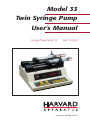
Model 33
Twin Syringe Pump
User's Manual
Syringe Pump Model 33
MA1 55-3333
Publication 5390-001-REV-D
WEEE/RoHS Compliance Statement
EU Directives WEEE and RoHS
To Our Valued Customers:
We are committed to being a good corporate citizen. As part of that commitment,
we strive to maintain an environmentally conscious manufacturing operation. The
European Union (EU) has enacted two Directives, the first on product recycling
(Waste Electrical and Electronic Equipment, WEEE) and the second limiting the use
of certain substances (Restriction on the use of Hazardous Substances, RoHS).
Over time, these Directives will be implemented in the national laws of each EU
Member State.
Once the final national regulations have been put into place, recycling will be offered
for our products which are within the scope of the WEEE Directive. Products falling
under the scope of the WEEE Directive available for sale after August 13, 2005 will
be identified with a “wheelie bin” symbol.
Two Categories of products covered by the WEEE Directive are currently exempt
from the RoHS Directive – Category 8, medical devices (with the exception of
implanted or infected products) and Category 9, monitoring and control instruments.
Most of our products fall into either Category 8 or 9 and are currently exempt from
the RoHS Directive. We will continue to monitor the application of the RoHS
Directive to its products and will comply with any changes as they apply.
• Do Not Dispose Product with Municipal Waste
• Special Collection/Disposal Required
Table of Contents
1
Harvard Apparatus Model 33 Twin Syringe Pump User's Manual
SUBJECT
PAGE NO.
Warranty and Repair Information ....................................2
General Safety Summary ..................................................3
Specifications ....................................................................4
Features ..............................................................................5
Initial Setup ........................................................................6
Loading Syringes ..............................................................7
User Interface:
Description of Keys ......................................................9
Entering Data ..................................................................10
Operation:
Diameters ....................................................................11
Pumping Rates ............................................................11
Selecting the Run Mode ..............................................11
Selecting the Pumping Directions ..............................11
Running the Pump ......................................................11
Single Syringe Operation ............................................11
Valve Control Box ............................................................12
Pinch Valve Connectors ............................................13-14
External Control and Interfaces:
Attaching/Configuring a Pump Chain ..........................15
TTL Devices ................................................................16
Foot Switch Input ........................................................16
Pump Chain Commands:
Pump Commands and Responses ............................18
Pump Chain Error Messages ......................................21
Appendices:
A. Syringe Diameters in mm........................................22
B. Nominal Min/Max Flow Rates ................................23
C. Command Information ............................................24
D. RS-232 Specifications ............................................25
E. TTL Connector Specifications ................................25
F. Pump to PC Connection..........................................26
G. Maintenance ............................................................27
H. Troubleshooting ......................................................28
I. Accessories ............................................................29
J. Custom Applications................................................30
www.harvardapparatus.com
Warranty and Repair Information
2
Harvard Apparatus Model 33 Twin Syringe Pump User's Manual
Serial Numbers
All inquires concerning our product should refer to the serial number of the unit. Serial
numbers are located on the rear of the chassis.
Calibrations
All electrical apparatus is calibrated at rated voltage and frequency.While the flow will
stay calibrated, the peak will vary.
Warranty
Harvard Apparatus warranties this instrument for a period of two years from date of
purchase.At its option, Harvard Apparatus will repair or replace the unit if it is found to
be defective as to workmanship or material.
This warranty does not extend to damage resulting from misuse, neglect or abuse, normal
wear and tear, or accident.This warranty extends only to the original customer purchaser.
IN NO EVENT SHALL HARVARD APPARATUS BE LIABLE FOR INCIDENTAL OR
CONSEQUENTIAL DAMAGES. Some states do not allow exclusion or limitation of incidental or consequential damages so the above limitation or exclusion may not apply to
you.THERE ARE NO IMPLIED WARRANTIES OF MERCHANTABILITY, OR FITNESS
FOR A PARTICULAR USE, OR OF ANY OTHER NATURE. Some states do not allow
this limitation on an implied warranty, so the above limitation may not apply to you.
If a defect arises within the two-year warranty period, promptly contact Harvard
Apparatus, Inc. 84 October Hill Road, Building 7, Holliston, Massachusetts
01746-1371 using our toll free number 1-800-272-2775, or outside the U.S. 508-8938999. Goods will not be accepted for return unless an RMA (returned materials authorization) number has been issued by our customer service department.The customer is
responsible for shipping charges. Please allow a reasonable period of time for completion of repairs, replacement and return. If the unit is replaced, the replacement unit is
covered only for the remainder of the original warranty period dating from the purchase of the original device.
This warranty gives you specific rights, and you may also have other rights which vary
from state to state.
Repair Facilities and Parts
Harvard Apparatus stocks replacement and repair parts.When ordering, please describe
parts as completely as possible, preferably using our part numbers. If practical, enclose
a sample or drawing.We offer a complete reconditioning service.
CAUTION
This pump is not registered with the FDA and is not for clinical use on human patients.
CAUTION: Not for clinical use on human patients.
Publication 5390-001-REV-D
General Safety Summary
Harvard Apparatus Model 33 Twin Syringe Pump User's Manual
3
Please read the following safety precautions to ensure proper use of your syringe
pump. To avoid potential hazards and product damage, use this product only as
instructed in this manual.
To Prevent Hazard or Injury:
Use Proper Line Cord
Use only the specified line cord for this product and make sure line cord is certified
for country of use.
Ground the Product
This product is grounded through the grounding conductor of the power cord. To
avoid electric shock, the grounding conductor must be connected to earth ground.
Before making any connections to the input or output terminals of the product, ensure
that the product is properly grounded.
Make Proper Connections
Make
sure
all
connections
are
made
properly
and
securely.
Any signal wire connections to the unit must be no longer than 3 meters.
Observe all Terminal Ratings
Review the operating manual to learn the ratings on all connections.
Use Proper Fuse
Use only specified fuses with product.
Avoid Exposed Circuitry
Do not touch any electronic circuitry inside of the product.
Do Not Operate with Suspected Failures
If damage is suspected on or to the product do not operate the product. Contact qualified service personnel to perform inspection.
Place Product in Proper Environment
Review the operating manual for guidelines for proper operating environments.
Observe all Warning Labels on Product
Read all labels on product to ensure proper usage.
CAUTION
Refer to Manual
Protective Ground
Terminal
www.harvardapparatus.com
Specifications
Harvard Apparatus Model 33 Twin Syringe Pump User's Manual
4
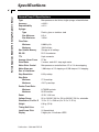
Harvard Pump 33 Specifications
Type
Microprocessor dual drive, single syringe, infuse/withdraw
Accuracy
±0.35%
Reproducibility
±0.1%
Syringe:
Type
Plastic, glass or stainless steel
Size Minimum
0.5 µ l
Size Maximum
140 ml
Flow Rate:
Minimum
0.0004 µ l/hr
Maximum
106.6 ml/min
Non Volatile Memory
Storage of all settings
RS-232
RJ11-4 conductor
TTL
9-pin connector
Average Linear Force
57 lbs
Drive Motor
2 motors, each 0.9° step angle motor
Motor Drive Control
Microprocessor controlled from 1/2 to 1/4 microstepping
Motor Steps per
Rev. of Leadscrew
1,600 steps at 1/2 stepping or 3,200 steps at 1/4 stepping
Step Resolution
0.33 µ m/step
Step Rate:
Minimum
27.3 sec/step
Maximum
416.7 µ sec/step
Pusher Travel Rate:
Minimum
0.726699 µ m/min
Maximum
95.25 mm/min
Power
45 W, 1.0 A fuse
Voltage Range
95 to 130 VAC, 60 Hz; 220 to 260 VAC, 50 Hz, selectable
Dimensions, H x W x D
15.2 x 31.1 x 28.6 cm (6 x 12.5 x 11.25 in)
Weight
6.8 kg (15 lb)
Timing Belt Drive
2:1
Lead Screw Pitch
24 threads/inch
Display
5 digits plus 14 indicator LEDS
Publication 5390-001-REV-D
Features
5
Harvard Apparatus Model 33 Twin Syringe Pump User's Manual
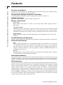
Pressure and Speed
Pump 33 can deliver up to 106.60 ml/min with a 140 ml syringe,and is capable of pressures of up to 99.5 PSI with a 20 ml syringe.
Independent Syringe Diameters and Rates
In the Proportional Mode, separate syringe types and rates may be set.
Variable Syringes
Enter the inside diameter of the syringes being used.
Modes of Operation
Auto Stop
Both syringes will operate at same rate and stop when either syringe reaches a
limit stop.
Continuous Run
With both syringes operating at same rate, when end of travel is reached, the pump
automatically reverses the direction of travel for both syringes.The external valves,
optionally attached to the syringes, will be automatically activated or deactivated.
Proportional
Pump operates as in Auto Stop, but independent rates and diameters are set for each
syringe.
Parallel/Reciprocal Operation
Syringes may pump in the same direction (parallel) or opposite directions (reciprocal).
External Connections
TTL
Allows pump operations to be synchronized with external devices or by a person
at a distance from the pump. Direction of pump travel can be set via a TTL pin.
Also, TTL pins are used to control an external valve for refilling and provide an
output to indicate whether or not the pump is running. Additional TTL pins are
available for general use.
RS-232
Multiple pumps can be chained together and remotely controlled from a computer or any device communicating via RS-232.
Non-Volatile Memory
All operational data entered into the pump from the keypad or requested to be saved
via RS-232, will be stored. On power up, all settings from when it was powered down
will be recalled and the display will blink until the pump receives its first command.
Stall Detection
An optical detector on each motor is used to verify expected movement of the motors.
If motor is prevented from turning due to jamming or kinking of the tubing, the pump
stops and the display indicates a stall condition by blinking the run light and the
syringe direction light of the stalled syringe. Pump 33 employs a microcontroller
which controls a small step angle stepping motor that drives a lead screw and half nut.
Microstepping techniques are used to further reduce the step angle making flow pulsation negligible. A keypad is used for entry of operating data to the pump or data can
be entered via RS-232. The microcontroller calculates the cross-sectional area of the
syringe selected and calibrates the flow rate.
www.harvardapparatus.com
Initial Setup
Harvard Apparatus Model 33 Twin Syringe Pump User's Manual
6
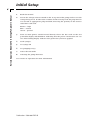
1.
Read the manual.
2.
Locate the voltage selector switch on the rear panel of the pump and set it to the
voltage being used. If other than 115VAC, 60 Hz is being used, the plug must be
cut off and an appropriate plug installed, observing the polarity of the international line cord used:
Brown – high
Blue – neutral
Green – ground
3.
Turn on main power switch located directly above the line cord on the rear
panel.The display will illuminate indicating that the power connections are correct. The flashing display indicates that power has just been applied.
4.
Load syringes.
5.
Set syringe ID
6.
Set pumping rate(s)
7.
Select the run mode
8.
Selecting the pump direction
See section on operation for more information
Publication 5390-001-REV-D
Loading Syringes
Harvard Apparatus Model 33 Twin Syringe Pump User's Manual
7
1
2
4
3
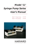
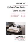
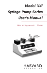
Figure 1. Syringe Loading
1. The syringe holder and pusher block are fitted with movable retaining brackets
which hold the syringe barrel and plunger when refilling.When loading the
syringe into the pump, it is necessary to adjust these brackets.The pusher block
is fitted with a mechanism to release the drive nut from the leadscrew.This
allows the block to move freely so the syringe to be loaded.
2. Loosen the screws on the syringe block and pusher block to free the retaining
brackets (2 and 3, Figure 1)
3. To free the pusher block from the leadscrew, turn the knob on the front of the
block (1) until the pin in the knob slips into the hole in the block.
4. The syringe clamp locking screw on the right side of the syringe block (4)
should be loosened and the clamp rotated to the side.
5. Place the syringe barrel on the syringe holder block and move the pusher block
to accommodate the plunger.
6. Make sure the syringe barrel flange and the plunger flange are held by the retaining clamps. Press the retaining brackets firmly against the flanges and tighten the
retaining screws.
7. Rotate the syringe clamp and press down firmly on the syringe barrel. Secure in
place by tightening the locking screw (4).
Setting Limit Stops
To set the limit stops, loosen thumbscrews on limit stops and slide stops to desired
travel limits (infuse limit & refill), tighten thumbscrews.
www.harvardapparatus.com
User Interface
Harvard Apparatus Model 33 Twin Syringe Pump User's Manual
8
Auto Stop
Proportional
ml/min
Syringe 1
µl/min
Continuous
Remote
ml/hr
Syringe 2
µl/hr
Run
mm
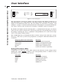
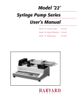
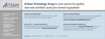
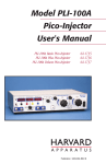
Figure 2. User Interface
The user interface consists of a display area and a keypad. The display consists of a 5
digit LED display and 14 LED indicators. The display will be showing either the default
display or an informational message. The two syringes are referred to as Syringe 1 and
Syringe 2. Syringe 1 is located towards the front and Syringe 2 is located towards the
rear. Rate 1 refers to the set flow rate of Syringe 1 and Rate 2 refers to Syringe 2.
By default, the display will be showing Rate 1. Informational messages are shown
when the user queries another data value by pressing the corresponding key, or when
the pump is alerting the user to a problem. Such problems are a value out of range
(oor) or the pump stalling (StALL).
The 14 LED indicators are divided into three sections: Pump mode and state, syringe
directions, and units of value being displayed. See Figure 2.The LED indicators are
as follows:
Pumping Mode and State LEDs
Auto Stop
Proportional
Continuous
Remote
Run
Meaning
Pump is in Auto Stop mode
Pump is in Proportional mode
Pump is in Continuous mode
Pump Chain communication
At least one motor is operating
Syringe Directions LEDs
Comprising of 4 indicators, these LED’s indicate the direction of the syringes when
illuminated. When blinking, indicates the corresponding motor is stalled, or data
pertaining to that syringe is being entered.
Unit LEDs
ml/min
µl/min
ml/hr
µl/hr
mm
Publication 5390-001-REV-D
Meaning
milliliters per minute
microliters per minute
milliliters per hour
microliters per hour
millimeters
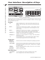
User Interface: Description of Keys
Harvard Apparatus Model 33 Twin Syringe Pump User's Manual
9
Proportional Only
8
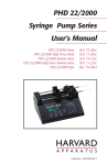
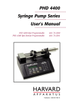
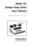
Figure 3. Keypad Interface
The keypad consists of 21 keys used for entering control information and data into the
pump. These keys are grouped into 3 sections (see Figure 3 above): Set keys, toggle
keys, and data entry keys.
Set Keys
Set
Allows modification of a data item in this group of keys.To
modify a data item, press the relevant key after pressing the
SET key.
Rate 1
Displays/sets current rate of syringe 1. Also syringe 2 rate if
current mode is not Proportional. Scrolls through rate units
when setting.
Rate 2
Displays/sets current rate of syringe 2. Scrolls through rate
units when setting. Key only valid in Proportional mode.
Diameter 1
Displays/sets current diameter of syringe 1. Also diameter of
syringe 2 if current mode is not Proportional.
Diameter 2
Displays/sets current diameter of syringe 2. Key only valid in
Proportional mode.
“1”
Used to display and set current Pump Chain address and to
scroll through supported baud rates while setting.
Toggle Keys
Parallel/
Reciprocal
Chooses between Parallel and Reciprocal pumping operation.
Select Mode
Chooses between Proportional, Continuous Run, or Auto Stop.
LED indicators display current mode. Pump must be stopped
to change modes.
Change
Direction
Reverses direction of both syringes and sets the valve control
output as appropriate.
Run/Stop
Starts or stops the pump.
Data Entry Keys
1 through 0, .
Used to facilitate the entering of numeric data values.
Enter
Stores displayed data value when entering data.
www.harvardapparatus.com
Entering Data
10
Harvard Apparatus Model 33 Twin Syringe Pump User's Manual
Set Keys
The keys in this group are used to modify or review settings of the pumps control
d
a
t
a
.
To review the current setting of a control data item, simply hold down the relevant
key and the data setting will appear in the display.
To modify a data setting, first press then release the green SET key. The display will
then read “SET”. Press the key in the SET key group of the data item that is to be modified. The display will show the current setting. Data is entered into the pump by
either entering a numerical value or, in the case of entering a baud rate, by scrolling
through a menu of choices. Always press ENTER to terminate each data request by the
pump.
When entering a numerical value, the LEDs corresponding to the data being entered
will blink. Using the yellow data entry keys on the right side of the keypad (see Figure
3) enter the new data value. Up to five digit numbers are accepted for rates and diameters, including up to four decimal places. Entering more than five digits will clear the
previous five digits in the display. Press the green ENTER key when the desired data
value is displayed.
If the data value entered is outside the pump’s operating parameters, the display will
read “oor” meaning “Out of Range”. Pressing any key will restore the display with the
original data value. Enter another data value within the pump’s parameters or just
press ENTER to reuse the original data value.
The data value entered can be reviewed as described above. Note: Certain data items
have multiple settings. For these, after the ENTER key is pressed, the display will
prompt you for the additional information. Various rules apply to when, what and how
data can be set at various times. See the relevant section for further details.
Toggle Keys
The keys in this group, when pressed successively, select different states. Each state
change is accompanied by a corresponding change in status LED display.
To operate, Pump 33 needs to know the diameter(s) of the syringes, the rate(s) of
pumping, pumping directions, and the mode of operation. Except for Proportional
mode, syringe 2 is assumed to be the same diameter as syringe 1 and will pump at
same rate as syringe 1.
Publication 5390-001-REV-D
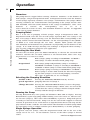
Operation
11
Harvard Apparatus Model 33 Twin Syringe Pump User's Manual
Diameters
The pump must be stopped when entering a diameter. Diameter 1 is the diameter of
both syringes, except in Proportional mode. In Proportional mode, enter the diameter
of each syringe separately; Diameter 1 for syringe 1 and Diameter 2 for syringe 2.When
entering a diameter, the 2 direction LEDs corresponding to the syringe and the “mm”
LED will blink. Enter the inside diameter of the syringe in millimeters. After a new
diameter
is
entered
the
corresponding
rate
is
set
to
0.
This is done for reasons of safety. The maximum diameter is 50 mm. See Appendix
A for a list of syringe diameters.
Pumping Rates
Rate 1 is the rate of pumping of both syringes, except in Proportional mode. In
Proportional mode, enter the rate of each syringe separately, Rate 1 for syringe 1 and
Rate 2 for syringe 2.When entering a rate, the directional LEDs corresponding to the
syringe and the current units LED will blink. Use the corresponding rate key (RATE 1
or RATE 2) to scroll through the rate units: ml/min, ml/hr, µl/min and µl/hr.
The minimum and maximum rates permitted vary depending on the diameter of the
syringe. If an “OOR” message, meaning “Out of Range” is displayed when entering a
rate, try using a different syringe for your application.
Selecting the Run Mode
To select the run mode, press the SELECT MODE key to advance the run mode LED
indicator. Advance the run mode indicator to the desired mode, either Auto Stop,
Proportional, or Continuous mode.
Auto Stop
Proportional
Continuous
Both syringes pump according to DIAMETER 1 and RATE 1
until syringe 1 reaches the limit switch, pump stops.
Each syringe pumps independently; syringe 1 according to
DIAMETER 1 and RATE 1, syringe 2 according to DIAMETER 2
and RATE 2. When syringe 1 reaches limit switch, pump stops.
Both syringes pump according to DIAMETER 1 and RATE 1.
When syringe 1 reaches limit switch, the direction of pumping for both syringes is reversed and pumping continues.
The valves, if applicable, are set accordingly.
Selecting the Pumping Directions
Parallel or ReciPressing the PARALLEL/ RECIPROCAL key reverses
procal Operation pumping direction of syringe 2.
Change Direction Pressing the CHANGE DIRECTION key reverses the pumping directions of both syringes. When valves are used in the
system then the valve(s) setting(s) will be changed simultaneously with the change in direction.
Running the Pump
Pressing RUN/STOP key starts pump and illuminates Run LED on display. Pressing
RUN/STOP key again stops pump. While running, a new rate can be set. The new rate,
for relevant syringe(s), takes effect when ENTER key is pressed. Pump will operate
according to selected run mode. Pump can also be started and stopped via external
controls. If operation of one of the motors is impeded, both motors will stop and display will read“StALL”, with the“run”LED and the direction LED of stalled syringe blinking. Investigate cause of stalling and then press RUN/STOP key to resume pumping.
Single Syringe Operation
To operate only one syringe, select the Proportional mode and set the rate of the
syringe not in use to 0. Set the diameter and rate of the other syringe to discard
values.
www.harvardapparatus.com
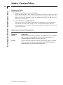
Valve Control Box
12
Harvard Apparatus Model 33 Twin Syringe Pump User's Manual
Setting up Valve
Set up consists of:
1. Pump to Valve Electrical Connections:
The cable fitted with a male 9 pin D-sub connector must be connected to the
female D-sub connector on the rear of the Model 33 Syringe Pump. The Valve
Power can now be swiched on with the illuminated power On/Off switch on
the front valve housing.
2. Valve tubing to syringe hook up:
The valve(s) are de-energized when the front mechanism (#1) is running in
the INFUSE direction. The syringe on the #1 mechanism when infusing
should therefore be connected to the lower tubing in the pinch valve (see figures on next page).
Continuous Delivery Valve Boxes
Model No.
Description
55-7000
Pump 33 Continuous Delivery Valve Box, normal pressure, 30 p.s.i. supplied
with 3.2 mm ID X 6.4 mm OD (1/8” ID X 1/4” OD) silastic tubing and a
connector cable for connection to the syringe pump.
55-7001
Pump 33 Continuous Delivery Valve Box, high pressure, 200 p.s.i. supplied
with 6.4 mm (1/4) OD stainless steel tubing with SWAGELOK® fittings and
connector cable for connection to the syringe pump.
Publication 5390-001-REV-D
Pinch Valve Connectors
Harvard Apparatus Model 33 Twin Syringe Pump User's Manual
13
Figure 4. Pinch Valve Connections
Figure 5. Continuous Delivery. Pump in Reciprocal Mode.
Figure 6. Dual Delivery followed by Refill. Pump in Parallel Mode.
www.harvardapparatus.com
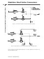
Stainless Steel Valve Connectors
Harvard Apparatus Model 33 Twin Syringe Pump User's Manual
14
Figure 7. Continuous Delivery. Pump in Reciprocal Mode.
Figure 8. Dual Delivery followed by Refill. Pump in Parallel Mode.
Swage lock fittings should be finger tight plus 1-1/4 turns. Tubing is 304, stainless 1/4"
OD, wall thickness 0.035"
Publication 5390-001-REV-D
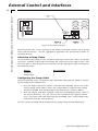
External Control and Interfaces
Harvard Apparatus Model 33 Twin Syringe Pump User's Manual
15
Figure 9. External Interface
External devices that can be attached to the Pump 33 include external valves, pump
chain, and TTL devices. See the appropriate appendixes for specification details on
attaching devices.
Attaching a Pump Chain
On the back of the pump are two telephone jack type connectors. These are the RS232 ports. Looking at the back of the pump, the connector on the right is port 1 and
the left is port 2. Attach the RS-232 connectors in the appropriate port according to
the following chart:
Device
Port Number
Computer
Pump Chain
1
2
Configuring the Pump Chain
After pressing SET and 1, the Remote LED will blink, indicating the pump is requesting its pump chain configuration:
1. First, the display will show “Adr:nn”, with the colon blinking, where “nn” is the
current pump chain address. Enter the 2 digit address assigned to the pump
and press ENTER. Note: Each pump in the chain needs a unique address.
2. Next, the display will show “b:nnnn”, with the colon blinking, where “nnnn” is
the current baud rate. Use the 1 key to select between the supported baud
rates: 300, 1200, 2400 and 9600; then press ENTER. Note: Each pump in the
chain must have the same baud rate.
See the section on Pump Chain Commands for pump chain control information.
www.harvardapparatus.com
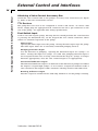
External Control and Interfaces
16
Harvard Apparatus Model 33 Twin Syringe Pump User's Manual
Attaching a Valve Control Accessory Box
Attach the valve control cable to the pump’s accessory valve connection (see Figure
9). Refer to the Valve Control Box section.
TTL Devices
The pump does not need to be configured to attach a TTL device. To attach a TTL
device, simply plug the appropriate TTL connector into the 9 pin connector on the
rear of the pump. See Appendix E for wiring specifications.
Foot Switch Input
Used to start and stop the pump. Pressing the foot switch performs the same function
as pressing the RUN/STOP key on the keypad. The foot switch connector allows
remote or automated operation of the pump.
Timer Input
Opening the timer input starts the pump. Closing the timer input stops the pump.
The timer input allows for an externally controlled pumping interval.
Pumping Direction Input
Sets the direction of pumping. Opening the directional input sets syringe 1 to
infuse. Closing the input sets syringe 1 to refill. The pumping direction input is
not recognized when data is being entered from the keypad. Syringe 2 changes
direction appropriately. Also, the valve control output is set appropriately.
Directional Indicator Output
The Directional Indicator output is an indicator of the direction of pump travel. When
the output is a logical high, syringe 1 is set to infuse. A logical low indicates refill. A
valve attached to this output enables automatic selecting of infuse and refill vessels.
Running Indicator Output
Provides a signal to another device indicating whether or not the pump is running.
Publication 5390-001-REV-D
Pump Chain Commands
Harvard Apparatus Model 33 Twin Syringe Pump User's Manual
17
The Pump Chain RS-232 interface is used to enhance the control applications of the
Pump 33. This interface allows all control information to be entered into the pump
from an external source such as a computer. In addition, this interface allows up to
100 Pump 33’s or, in certain cases, other RS-232 devices to be controlled from a single
RS-232 communication port on a computer. Assign each pump in the pump chain a
unique address from 0 to 99. This address is used to identify which pump is to receive
a command and which pump is responding. Configure each pump with its assigned
address and the baud rate being used (See External Control & Interfaces). When a
pump is sent a command, or a request is made for its prompt, the Remote LED on the
display will illuminate, indicating that the pump is receiving pump chain commands.
The LED remains illuminated until the pump is turned off or SET and 1 is entered on
the keypad, indicating a change in the pump chain configuration.
A pump will not respond to pump chain communication while it is in a setting mode
(entered when the user presses the SET key). The pump can still be controlled from
the keypad while it is in a pump chain. Control data that is changed via RS-232 will
NOT be stored in the pump’s non-volatile memory unless requested with the “SAV”
command or other data is changed from the keypad. Each command sent to the pump
chain is a string of ASCII characters, with leading zero’s on numbers and all spaces
optional. Numbers are a maximum of five digits. The following symbols are used in
describing the commands:
Symbol
[. . . ]
{. . . }
|
f
d
<cr>
<lf>
<float>
<integer>
<text>
Meaning
optional
select one
either–or
digits 0-9 or a decimal point
digits 0-9
carriage return (ASCII 13)
line feed (ASCII 10)
ffffff
ddddd
any string of ASCII characters
Command Formats
<cr>
Meaning
Stops all pumps. All pumps on the pump
chain interpret this as a stop command, but
do not respond with a prompt.
Request for prompt. The pump with the
indicated address responds with its prompt.
Sends a command to a pump. The pump
with the indicated address executes the
command then responds with its prompt.
The optional pump address, if not specified, will default to pump address 0.
pump address, <cr>
optional pump address,
command, <cr>
After each command is received and executed, the pump acknowledges the command
with a prompt. Preceding the prompt will be the text response, if applicable. The text
response will be one or more lines of ASCII text, each preceded by a line feed and terminated by a carriage return:
<lf>, <text>, <cr>
www.harvardapparatus.com
Pump Chain Commands
Harvard Apparatus Model 33 Twin Syringe Pump User's Manual
18
A prompt is a string of ASCII characters sent by a pump, indicating the pump’s address
and its present state:
<lf>, 1 or 2 digit address, prompt character
Prompt Characters
:
>
<
*
Meaning
Pump stopped
Syringe 1 infusing
Syringe 1 refilling
Pump stalled
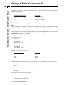
Pump Commands and Responses
RUN
Starts pumping according to the present setting of the pump. If pump already pumping, a “Not Applicable” error is returned.
STP
Stops pump if it was running. If pump already stopped,a“NotApplicable”error is returned.
RAT [{A|B}] [[<float> [<units>]]
Request to set or query infusion rate settings.
Set syringe 1 rate:
RAT rate
RAT rate units
RAT A rate
RAT A rate units
Set syringe 2 rate (only valid in proportional mode):
RAT B rate
RAT B rate units
Rate is of the format:
ffffff
Units are one of
UM
UH
MM
MH
Meaning
µl/mn
µl/hr
ml/mn
ml/hr
Rate 2 is only accepted when mode is Proportional. If rate is accepted and valid, rate
will become the new rate. If the rate is invalid, an “Out Of Range” error is returned.
Query syringe 1 rate:
RAT
RAT A
Query syringe 2 rate (only valid in proportional mode):
RAT B
Response is of the following format:
f f f f f f <units>
Where units are one of the following:
ml/mn, ml/hr, µl/mn, µl/hr
Publication 5390-001-REV-D
Pump Chain Commands
Harvard Apparatus Model 33 Twin Syringe Pump User's Manual
19
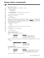
DIA [{A|B}] [<float>]
Request to set or query syringe diameter settings.
Set syringe 1 diameter:
DIA diameter
DIA A diameter
Set syringe 2 diameter (only valid in proportional mode):
DIA B diameter
Corresponding syringe’s rate will be zeroed.
Diameter is of the format:
ffffff
Units are millimeters.
Diameter 2 is only accepted when mode is proportional. If diameter is accepted and
valid, diameter will become the new diameter. Diameter will not be accepted if the
pump is running and a “Not Applicable” error is returned. If the diameter is invalid, an
“Out Of Range” error is returned.
Query syringe 1 diameter:
DIA
DIA A
Query syringe 2 diameter (only valid in proportional mode)
DIA B
Response is of the following format:
ffffff
Units are millimeters.
MOD [{AUT|PRO|CON}]
Request to set or query pumping mode
SET:
Command
MOD AUT
MOD PRO
MOD CON
Meaning
Puts pump in Auto Stop mode
Puts pump in Proportional mode
Puts pump in Continuous mode
If pump is running,command will not be accepted and a“NotApplicable”error is returned.
Query:
MOD
Possible Responses
AUT
PRO
CON
Meaning
Auto Stop mode
Proportional mode
Continuous mode
DIR [{INF|REF|REV}]
Request to set or query pumping direction of syringe 1.
SET:
Command
DIR INF
DIR REF
DIR REV
Meaning
Sets syringe 1 pumping direction to infusion
Sets syringe 1 pumping direction to refill
Reverses pumping direction of syringe 1
Direction of syringe 2 is set appropriately.
www.harvardapparatus.com
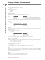
Pump Chain Commands
Harvard Apparatus Model 33 Twin Syringe Pump User's Manual
20
Query pumping direction of syringe 1:
DIR
Response will be one of:
INFUSE
REFILL
PAR [{ON|OFF}]
Request to set or query Parallel or Reciprocal setting.
Command
PAR ON
PAR OFF
SET:
Meaning
Sets syringes to parallel pumping direction.
Sets syringes to reciprocal pumping direction.
Direction of syringe 2 changes appropriately,while direction of syringe 1 does not change.
Query:
PAR
Possible Responses
ON
OFF
Meaning
Parallel
Reciprocal
IN <d>
Request to read in the TTL logic level at the specified pin,“d”, on the external 9 pin
D-SUB connector.
Valid pin numbers for input are:
6, 7 and 8
Possible Responses
ON
OFF
Meaning
TTL level high
TTL level low
If the pin specified is invalid, a “Not Applicable” error is returned.
OUT <d> = {ON|OFF}
Request to set the TTL logic level at the specified pin“d”on the external 9 pin D-SUB connector.
ON – Set pin to a logic high
OFF – Set pin to a logic low
Valid pin numbers for output are:
4 and 5
If the pin specified is invalid, a “Not Applicable” error is returned.
SAV
Request to save pump settings in the pumps non-volatile memory (NOVRAM).
Normally, settings changed from a pump chain are not stored in the pump’s NOVRAM
and are lost after power down.
VER
Request for version of pumps embedded software.
Response for the present version will be: 33V2.0
Publication 5390-001-REV-D
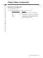
Pump Chain Commands
21
Harvard Apparatus Model 33 Twin Syringe Pump User's Manual
Pump Chain Error Messages
Error messages are in the format:
<lf>, <message>, <cr>,
and are followed by a prompt. <Message> is one of the following:
Possible Responses
Meaning
?
Syntax error in a received command
NA
Command “Not Applicable” at this time.
OOR
“Out Of Range”. Control data is out of
pump's operating range.
www.harvardapparatus.com
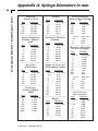
Appendix A: Syringe Diameters in mm
Harvard Apparatus Model 33 Twin Syringe Pump User's Manual
22
Harvard
Stainless Steel
Size
Diameter
8 cc
9.525 mm
20
19.130
50
28.600
100
34.900
200
44.755
––––––––––––––––––––––
Becton Dickinson
Plastic ‘Plastipak’
Size
Diameter
Size
Terumo
Diameter
3 cc
8.95 mm
5
13.00
10
15.80
20
20.15
30
23.10
60
29.10
––––––––––––––––––––––
Sherwood–Monoject
Plastic
Size
Diameter
1 cc
4.78 mm
3
8.66
5
12.06
10
14.50
20
19.13
30
21.70
50/60
26.70
––––––––––––––––––––––
1 cc
4.65 mm
3
8.94
6
12.70
12
15.90
20
20.40
35
23.80
60
26.60
140
38.40
––––––––––––––––––––––
Air–Tite
‘All Plastic’
Popper & Sons, Inc.
‘Perfektum’ Glass
2.5 cc
9.60 mm
5
12.45
10
15.90
20
20.05
30
22.50
50
29.00
––––––––––––––––––––––
0.25 cc 3.45 mm
0.5
3.45
1
4.50
2
8.92
3
8.99
5
11.70
10
14.70
20
19.58
30
22.70
50
29.00
100
35.70
––––––––––––––––––––––
Size
Diameter
Unimetrics
Series 4000 &
5000
Size
10 µl
25
50
100
250
500
1000
Diameter
0.460 mm
0.729
1.031
1.460
2.300
3.260
4.610
Publication 5390-001-REV-D
Size
Size
2 cc
5
10
20
30
50
Diameter
Renfac
Diameter
9.12 mm
12.34
14.55
19.86
23.20
27.60
SGE Scientific
Glass Engineering
Size
25 µl
50
100
250
500
Diameter
0.73 mm
1.03
1.46
2.30
3.26
1.0 ml
4.61 mm
2.5
7.28
5
10.30
10
14.57
––––––––––––––––––––––
Hamilton–Microliter
Series Gastight
Size
0.5 µl
1
2
5
10
25
50
100
250
500
Diameter
0.103 mm
0.1457
0.206
0.3257
0.460
0.729
1.031
1.46
2.3
3.26
1.0 ml
4.61 mm
2.5
7.28
5
10.3
10
14.57
25
23.0
50
32.6
––––––––––––––––––––––
Becton Dickinson
Glass-All Types
Size
0.5 µl
1
2.5
5
10
20
30
50
100
Diameter
4.64 mm
4.64
8.66
11.86
14.34
19.13
22.70
28.60
34.90
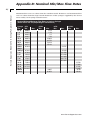
Appendix B: Nominal Min/Max Flow Rates
Harvard Apparatus Model 33 Twin Syringe Pump User's Manual
23
Minimum flow rates are taken from the smallest inside diameters and maximum flow
rates are taken from the largest inside diameters of the syringes supplied by the eleven
most widely used syringe manufacturers.
Nominal Minimum/Maximum Flow Rates for Various Syringes
(Actual Limits will vary depending on manufacturer)
Syringe µl/hr
Size
Min.
0.5 µl
0.0004
1 µl
0.0008
2 µl
0.0015
5 µl
0.0037
10 µl
0.0073
25 µl
0.0183
50 µl
0.0365
100 µl
0.0731
250 µl
0.1813
500 µl
1000 µl 0.7281
1 ml
0.7828
2 ml
2.8493
2.5 ml
1.8156
3 ml
2.5691
5 ml
4.9824
10 ml
7.2024
20 ml
12.5360
30 ml
16.1310
50 ml
24.4201
100 ml
140 ml
Max.
µl/min
Min.
Max.
ml/hr
Min.
Max.
ml/min
Min.
Max.10
0.79
1.58
3.1
7.93
15.829
39.756
79.519
159.46
23.751
95.418
102.580
373.430
237.950
336.710
653.010
0.087
0.1053
15.733
27.384
35.236
53.346
91.20
106.60
www.harvardapparatus.com
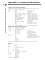
Appendix C: Command Information
24
Harvard Apparatus Model 33 Twin Syringe Pump User's Manual
Pump Chain Command Summary
All spaces in command are ignored. Maximum 5 digits per integer, or float data.
command
= > [<adr>] [<cmd>] <CR>
adr
= > [d]d
1 or 2 digit address
cmd
=>
Start pump
Stop pump
Set/query syringe 1 rate
Set/query syringe 2 rate
Set/query syringe diameter 1
Set/query syringe diameter 2
Set/query pumping mode
Set/query pumping direction
Set/query Parallel/Reciprocal
Read TTL pin d
Set TTL pin d
Save settings in NOVRAM
Query software version
units
= > {UM|UH|MM|MH}
RUN
STP
RAT [A] [<float> [<units> ] ]
RAT B [<float> [<units> ] ]
DIA [A] [<float>]
DIA B [<float>]
MOD [{AUT|PRO|CON}]
DIR [{INF|REF|REV}]
PAR [{ON|OFF}]
IN <d>
OUT <d> = {ON|OFF}
SAV
VER
µl/mn, µl/hr, ml/mn, ml/hr
Command Response Output Format:
output
response
prompt
adr
message
= > [<response>] <prompt>
= > <response> <response>
<lf> <message> <cr>
= > <lf> <adr> :
<lf> <adr> >
<lf> <adr> <
<lf> <adr> *
= > [d]d
=> ?
NA
OOR
<text>
<integer>
<float>
Stopped
Syringe 1 infusing
Syringe 1 withdrawing
Pump stalled
1 or 2 digit pump address
Unrecognized command
Command not presently applicable
Entered value out of range
All spaces ignored. Maximum 5 digits per integer or floating point number.
Legend
float
f
integer
d
b
cr
lf
text
< ...>
upper case
[ ...]
{ ...}
|
=>
=>
=>
=>
=>
=>
=>
=>
ffffff
d|.
ddddd
0|1|2|3|4|5|6|7|8|9
space
(ASCII 13)
(ASCII 10)
(any string of ASCII characters)
non-terminal
terminals
optional
select one
either-or
Publication 5390-001-REV-D
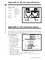
Appendix D: RS-232 Specifications
25
Harvard Apparatus Model 33 Twin Syringe Pump User's Manual
Pump Chain
Pump Port 1:
Pump Port 2:
Baud Rate:
Word Size:
Parity:
Stop Bits:
Computer
control side
Connection for
remainder of
pump chain
300, 1200, 2400
or 9600
8
none
2
Figure 9. RS-232 Specifications
Appendix E: TTL Connector Specs
TTL Connections are via a 9 pin D-sub type connector.All inputs are internally pulled
up to a logic high. All user definable pins are controlled via the IN and OUT pump
chain commands. See Pump Chain Commands.
Pin Assignments
1. Vss (Ground reference,
logic low)
2. Directional Indicator:
Low – Syring 1 Infusing
High – Syringe 1 Refilling
3. Pump Running Indicator
Low - Pumped Stopped
High - Pump Running
4. User Definable Output
5. User Definable Output
6. Foot Switch Input
Falling edge starts/stops pump
7. Timer Input
Figure 10. TTL Connector Specifications
Rising edge starts pump
Falling edge stops pump
Logic Low: 0 V – 0.5 V
Max. 2 mA current sink
8. Directional control input
Rising edge sets Syringe 1 to infuse Logic High: 2 V – 5 V
Falling edge sets Syringe 1 to refill
Max. 400 mA current source
9. Vcc (Logic High Reference)
www.harvardapparatus.com
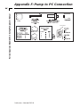
Appendix F: Pump to PC Connection
Harvard Apparatus Model 33 Twin Syringe Pump User's Manual
26
4/
“Pump”
22/2000
4400
Front View
6
RJ12 - 6 x 6
RJ11/RJ12
5
3
Publication 5390-001-REV-D
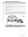
Appendix G: Maintenance
Harvard Apparatus Model 33 Twin Syringe Pump User's Manual
27
Pump 33 requires no special maintenance other than keeping it clean by avoiding accidental spills of pumped material.
The two guide rods and the lead screw should be sparingly lubricated periodically
with the Magnalube-G R grease provided with the pump. This Teflon R based grease
is available either from Harvard Apparatus or Carleton-Stuart Corp. 13-02 44th Ave.,
Long Island City, NY 11101.
Solvents of any type should never be used to
A mild detergent solution may be used to clean the keypad.
clean
the
pump.
Fuse Replacement
Make sure power cord is disconnected from main supply before replacing fuse.
Remove bottom cover on pump by removing four (4) rubber feet and four (4) screws.
Locate fuse on power supply module. Remove fuse from fuse clip. Use caution no to
break fuse when removing. Replace fuse, bottom cover, screws and rubber feet. For
continued fire protection replace fuse only with 250V fuse of the specified type and
rating. (3AG 1AMP 250V SLO-BLO)
Figure 11. Fuse Replacement
WARNING:
Use in manner not specified by manufacturer may
impair protection provided by equipment.
www.harvardapparatus.com
Appendix H: Troubleshooting
28
Harvard Apparatus Model 33 Twin Syringe Pump User's Manual
RS-232 Difficulties
Verify that the baud rates and data framing parameters on all devices are the same.
With a pump chain, a “Communication timeout” error on a computer is usually caused
by the computer errantly handshaking on the RTS, CS and/or DSR lines. Verify pins 4,
5 and 6, on the 25 pin connector, are jumpered on the computer side of the cable.
Display Messages:
All digits flashing
Pump has not received any commands since being powered on.
StALL
Also a syringe LED and Run LED flashing. This indicates that the pusher block travel
of the syringe corresponding to the syringe LED blinking has been impeded. This may
be caused by the syringe plunger hitting bottom, a kink in the tubing, syringe plunger
binding or any situation requiring more force to the head of the syringe than the pump
is capable of delivering. To restart the pump, remove the cause of stalling and press
RUN. The pump will continue the interrupted procedure where it stopped. Also note,
a large increase in the pumping rate while running could also stall the motor.
oor
Out of range. A value was entered or encountered in a pump program that was beyond
the pumps limits. Try using a different size syringe. Note that rates must be less than
42950. Express larger rates using different units.
----Key pressed is not applicable.
Publication 5390-001-REV-D
Appendix I: Accessories
Harvard Apparatus Model 33 Twin Syringe Pump User's Manual
29
Catalog No.
Product
MA1-55-4144
Foot Switch
MA1-55-7760
Daisy Chain Cable 2ft for connecting two or more pumps; need 1 cable
per pump
MA1-70-2022
RS-232 Connector Cable, 7ft, 9 pin D-Sub
MA1-55-7000
Continuous Delivery Valve Box, normal pressure, 30 p.s.i. supplied with 1/8”
ID x 1/4” OD silastic tubing and connector cable for connection to the
syringe pump.
MA1-55-7001
Continuous Delivery High Pressure Valve Box, high pressure, 200 p.s.i.
supplied with 1/4” OD 304 stainless steel tubing with SWAGELOK® fittings
and a connector cable for connection to the syringe pump.
www.harvardapparatus.com
Appendix J: Custom Applications
Harvard Apparatus Model 33 Twin Syringe Pump User's Manual
30
The Harvard 33 Syringe Pump lends itself to a multitude of OEM industrial applications, for all types of custom pumping or pilot plant applications. Please contact the
Harvard Technical Support Department if we can be of help.
Publication 5390-001-REV-D
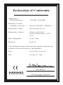
Declaration of Conformity
Application of
Council Directive(s):
Standard(s) to which
conformity is declared:
Manufacturer’s Name:
Manufacturer’s Address:
Type of Equipment:
Model No.:
73/23/EEC, 89/336/EEC
EN61010, EN50082-1, EN50081-1
Harvard Apparatus, Inc.
84 October Hill Road
Holliston, Massachusetts 01746
U.S.A.
Syringe Pump
Model 33
I, the undersigned, hereby declare that the equipment specified above
conforms to the above Directive(s) and Standard(s).
Place:
Date:
United States of America
November 11, 1996
(Signature)
Beth Bauman
(Full Name)
VP Engineering / Operations
(Position)
U.S.A.
U.K.
84 October Hill Road
Holliston, Massachusetts 01746
Fircroft Way, Edenbridge
Kent TN8 6HE
Web
France
Harvard Apparatus
Phone
Toll Free
Fax
E-mail
(508) 893-8999
(800) 272-2775
(508) 429-5732
bioscience@
harvardapparatus.com
www.harvardapparatus.com
1125 Dixwell Avenue
Hamden, CT 06514
Warner Instruments, Inc.
Phone
Toll Free
Fax
E-mail
Web
(203) 776-0664
(800) 599-4203
(203) 776-1278
[email protected]
www.warneronline.com
6010 Vanden Abeele Street
Saint Laurent, Quebec, H4S 1R9
Harvard Apparatus, Canada
Web
Phone
Fax
E-mail
Web
(44) 1732-864-001
(44) 1732-863-356
[email protected]
www.harvardapparatus.co.uk
6 Avenue des Andes
Miniparc – Bat. 8
F-91952, Les Ulis Cedex
Harvard Apparatus, S.A.R.L.
Phone
Fax
E-mail
(33) 1-64-46-00-85
(33) 1-64-46-94-38
[email protected]
Germany
Harvard Apparatus GmbH
Gruenstrasse 1
D-79232, March - Hugstetten
Hugo Sachs Elektronik
Canada
Phone
Toll Free
Fax
Toll Free
E-mail
Harvard Apparatus, Ltd.
(514) 335-0792
(800) 361-1905
(514) 335-3482
(800) 335-0792
sales@
harvardapparatus.ca
www.harvardapparatus.ca
Phone
Fax
E-mail
Web
(49) 0 7665-92-00-0
(49) 0 7665-92-00-90
[email protected]
www.hugo-sachs.de