1
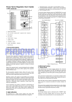
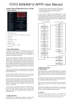
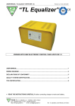
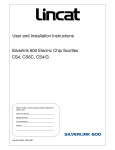
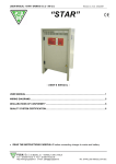
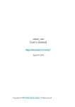
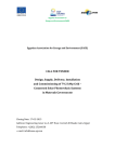
2012
[SMARTJUMPER:
MANUAL]
Energy saving system.
USER
SMARTJUMPER:
USER MANUAL
Contenido
1.
USER MANUAL SMARTJUMPER 1.0 Y 2.0 ............................................................................. 3
1.1.
SmartJumper Main Features ......................................................................................... 3
1.2.
Main Screen................................................................................................................... 4
1.3.
Startup Display .............................................................................................................. 4
1.4.
SmartJumper Controls................................................................................................... 5
1.5.
Menú ............................................................................................................................. 6
1.6.
Full menu chart ............................................................................................................. 7
1.7.
Instant data ................................................................................................................... 8
1.8.
Statistics ........................................................................................................................ 8
1.9.
Current alarms............................................................................................................... 9
1.10.
Configuration............................................................................................................. 9
1.10.1 System settings.......................................................................................................... 9
1.10.2 Date and time settings ............................................................................................ 10
1.10.3 Electricity test .......................................................................................................... 10
1.10.4 Home screen settings .............................................................................................. 10
1.10.5 Alarms Settings ........................................................................................................ 10
1.10.6 Allocation of Relays ................................................................................................. 11
1.10.7 Probes Test .............................................................................................................. 11
1.10.8 Reset statistics .......................................................................................................... 11
1.10.9 Full system reset...................................................................................................... 11
1.11.
Manual Control ....................................................................................................... 11
1.12.
Clocks....................................................................................................................... 12
1.13.
Software version..................................................................................................... 12
1.14.
Module specifications ............................................................................................. 13
1.14.1.
SJR-15D Saving device module 15 KVar Display Vía Radio .................................. 13
1.14.2.
Saving device module SJR-15KVar vía radio ........................................................ 14
1.14.3.
Saving device module SJR-35KVar vía radio ........................................................ 15
1.14.4.
Saving device module SJR-60KVar vía radio ....................................................... 16
1.14.5.
Saving device module SJR-85KVar vía radio ....................................................... 17
1.14.6.
CSL Digital console SMARTJUMPER 2.0 .............................................................. 18
1.14.7.
RES2 Digital Input Module / Temperature / radio relay outputs ........................ 19
1
SMARTJUMPER:
1.14.8.
USER MANUAL
MVR2 Measurement module via radio .............................................................. 20
2
SMARTJUMPER:
1.
USER MANUAL
USER MANUAL SMARTJUMPER 1.0 Y 2.0
1.1. SmartJumper Main Features
Power factor correction device. The device conducts and stores the active power
measurements, reactive power, maximum amps consumed , cosine phi, amps and voltages at
the facility.
It has a system for collecting digital inputs alarms or external events. It has a timetable system
for the activation of different devices hours and days depending on the programming
scheduled.
Basic Module SJR-15D
CSL Digital
1. POWER SAVING SYSTEM.
2. Viewing status.
3. Energy Consumption Control of facility.
4. Archival Data Display, Day, Month, Year.
5. Configurable Alarm System.
6. Power Factor Correction and Cos (Φ).
7. Easy navigation through the different options of the system.
8. Control of the Automatic or Manual.
9. Mono-phase measurement or Tri-Phasic
3
SMARTJUMPER:
USER MANUAL
1.2. Main Screen
System startup screen: Prepare the system for initialization.
1.3. Startup Display
1
2
3
6
4
8
9
10
5
7
11
When finished after turning on the system, all values will start automatically, we will
access the system home screen, showing the following information:
1.
2.
3.
4.
5.
6.
7.
8.
9.
10.
11.
1. System Time: Indicates the current system time.
2. Date System: Indicates the current system date.
3. Power Phases: Instant Active Power at each stage (Kw / h).
4. Voltage: Current voltage in each phase (V).
5. Relay status: Relay system indicator.
6. Intensity: Indicator bar of current intensity at phase (A).
7. Intensity: Current intensity phase numerical data (A).
8. Cos (Φ): Graph bar indicating the value of cos phi.
9. Operation mode: System operating mode (Auto-Manual).
10. Current expenditure: Consumption euro per hour (Euro / h).
11. Current Day: cumulative consumption per day (Euro)..
4
SMARTJUMPER:
USER MANUAL
1.4. SmartJumper Controls
21
25
22
23
24
26
Controles del SMART-JUMPER. Para controlar nuestro sistema tenemos el panel que
vemos en la figura superior.
SMART-JUMPER controls. To control our system we have the panel we see in the picture
above.
21 – Operation mode control (Automatic-Manual).
22 - Shortcut Key to the initial screen of the system.
23 - System Menu Key Access.
24 - Confirmation key (for access to sub-menus and so on).
25 - Keyboard navigation menus.
26 - Led indicator of the presence of alarms in the system.
5
SMARTJUMPER:
USER MANUAL
1.5. Menú
The main menu consists of the following options:
1. Instant Data: Instant data collected by SmartJumper, useful for monitoring network status .
2. Statistics. We can check cumulated data since our system has been launched.
3. Current Alarms: this sub-menu shows active alarms and alarm record.
4. Configuration: this sub-menu shows SmartJumper settings.
5. Manual control: the SmartJumper is designed for optimal automatic energy control
although, it also allows manual management.
6. Clocks: activation and deactivation of digital outputs with configurable schedule. (Activation
output by relay).
7. Software Version: indicates the software version and hardware of our SmartJumper.
Below we can view complete organization of all the options available to us in our system, to
be accessed via navigation keys
(No. 25) and the Enter key (No. 24)
.
6
SMARTJUMPER:
USER MANUAL
1.6. Full menu chart
Menu
Instant Data
Stadistics
Daily
Today
Monthly
Yesterday
Yearly
Phase Energy
L1
Phase Energy
L1
Current
Alarms
Configuration
Current
Alarms
Sistem
Settings
Timer 1
Line Settings
Timer 2
Timer 3
Alarms
Archival Data
Phase Energy
L1
Phase Energy
L1
Phase Energy
L2
Phase Energy
L2
Date Time
Settings
Phase Energy
L2
Phase Energy
L2
Phase Energy
L3
Phase Energy
L3
Eectricity
Price
Phase Energy
L3
Phase Energy
L3
Tri-Phase
Energy
Tri-Phase
Energy
Reset
Tri-Phase
Energy
Tri-Phase
Energy
Manual
Control
Clocks
Statistics
Alarms
Settings
7
Software
Version
SMARTJUMPER:
USER MANUAL
1.7. Instant data
At the time data display all the data we see the power line which is connected
SmartJumper.
1.8. Statistics
The stats menu shows data stored in memory. SmartJumper stores all data to be
checked by user at any time. The stored data is sorted by date, Current/Previous Day, Month,
Year for each of the 3 phases individually, and also for Three-phase configuration.
By selecting the sub-menus to get statistics screen that shows the final format data bars to
move through them we will use the navigation keys (No. 25)
back "arrow left. "
up and down, to go
Within each phase, and three-phase we will be navigating through the screens
described in the following chart:
8
SMARTJUMPER:
L1 Phase
L2 Phase
L3 Phase
USER MANUAL
Tri-Phase
Active
Power
Active
Power
Active
Power
Active
Power
Reactive
Power
Reactive
Power
Reactive
Power
Reactive
Power
Cos (Phi)
Cos (Phi)
Cos (Phi)
Max
Voltage
Max
Voltage
Max
Voltage
Min
Voltage
Min
Voltage
Min
Voltage
Max
Intensity
Max
Intensity
Max
Intensity
Min
Intensity
Min
Intensity
Min
Intensity
1.9. Current alarms
The alarm menu shows the alarms that are currently active. We may also view
alarms record, entering the option "Alarm Record" on screen.
When an alarm is active it shows a warning light on the control panel of the device. (No. 26).
1.10. Configuration
Through the configuration menu you can access the following sub-menus:
1.10.1 System settings
The options to this point are as follows.
Saving mode: Normal and Max saving mode choices.
Normal mode corrects the power factor of different lines, lines that are balanced.
9
SMARTJUMPER:
USER MANUAL
For lines that are not balanced normal mode produces the highest accuracy and energy
savings.
Probe type: Depending on the gauge of wire on which to be measured, you can choose
10/16/36mm probes.
Language: Shows different computer languages.
1.10.2 Date and time settings
Through this option you can set the system date and time
1.10.3 Electricity test
This option sets the price of electricity as follows:
• Price of active energy.
• Price of reactive power when cos is less than 0.8 f.
• Price of reactive power when the cos f is greater than 0.8 and less than 0.95.
1.10.4 Home screen settings
You can choose two types of home screens.
Cos fi: This screen also shows cos fi on each phase.
Consumption: Shows information comparing consumption of current and previous day of the
week.
1.10.5 Alarms Settings
You can program the following alarms
Maximum voltage alarm.
Minimum voltage alarm.
Maximum intensity alarm. When the current consumption exceeds this value an alarm in the
system goes on.
10
SMARTJUMPER:
USER MANUAL
1.10.6 Allocation of Relays
This screen selects the relay assigned to each of the following functions.
Alarm Relay
Relay Clock 1
Relay Clock 2
Relay Clock 3
1.10.7 Probes Test
Once installed, the computer can check that current probes are installed correctly.
When you run this option if one probe is inserted upside down or not in the proper phase, it
prompts you to operate correctly. Once you have made the suggested changes, retake the
probe test to check that everything is correct.
IMPORTANT. If there is any capacitor pack installed on facility, put it to sleep before the
probe test.
1.10.8 Reset statistics
This option will delete all statistics.
1.10.9 Full system reset
This option is used to set all system variables to their default
1.11. Manual Control
You can only access Manual control panel when system operating mode is “Manual”,
you can press hotkey to switch manual / automatic:
When operating in manual mode, we can activate and deactivate outputs in order to use
system manually. This is done through the buttons above and below, click "E" for executing.
11
SMARTJUMPER:
USER MANUAL
1.12. Clocks
In the menu we can set different timings on SmartJumper outputs, so we have
the ability to handle electrical appliances through our system.
SmartJumper has 3 outputs to relays that we can temporize to our liking. To access time
settings:
"Clocks" -> "time clocks" ->
Here we selected the state of the timer "ON", "OFF", the start time and end of our timing, and
also entering the configuration of the "Days" we can select the output relay and the days of
the week we want to activate the exit.
Note: When activated you can visualize a clock on the screen itself Clocks (Relay *) before the
status.
1.13. Software version
By accessing this option, you can see the software version you have on your system,
both the Digital and Power Software versions.
12
SMARTJUMPER:
USER MANUAL
1.14. Module specifications
All modules conform to the following standards:
89/392/CEE, 73/336/CEE, 73/23/CEE, IEC 60831- 1/2
1.14.1. SJR-15D Saving device module 15 KVar Display Vía Radio
Device:
Max correction 15KVar
Single-Phase Voltage: 230Vac
Tri-Phase Voltage: 400Vac
Relays REL1,REL2,REL3:
Aproved IEC/VDE
Max Voltage: 230Vac
Max Intensity: 3A
Power Input Terminals N,L1,L2,L3:
Aproved IEC/VDE
Max Voltage: 50Vac
Max Intensity: 25A
Intensity Probes:
Class 1.0
Linearity 0.5%
Frecuency 20 a 400Hz
IEC 60831- 1/2
Digital Inputs.
Voltaje output 5Vdc
Intensity: 50ma
Capacitors:
Operation Frecuency 50/60Hz
Regulations: IEC 60831- 1/2
13
SMARTJUMPER:
USER MANUAL
1.14.2. Saving device module SJR-15KVar vía radio
Nominal Voltage
230Vac/400Vac/440ac
Single Phase Power: L1+N
Tri-Phase Power:
L1+L2+L3+N
Nominal Voltage
15KVar
Capacitors
POLIMET
Stages Number
4 stages / 2 Single-Phase /2 Tri-Phase
Power Protection
1 fuse per phase 20A
Fixing:
Wall plastic cabinet
Phases Measurements
Independent 3 phases measurements
Adaptors not included
Display
5” monochrome LCD
Adaptors Type
EL10 / EL16 / EL36 (NO incluidas)
Digital Inputs
3
Digital Outputs
3 Contact voltage relays,
Max Relay Intensity
4A
Temperature Probe
Average range: -22 ºC to 80ºC
Radio System
Not included in all models
Radio Frecuency
2.4GHz
14
SMARTJUMPER:
USER MANUAL
1.14.3. Saving device module SJR-35KVar vía radio
Nominal Voltage
230Vac/400Vac/440ac
Single Phase Power: L1+N
Tri Phase Power:
L1+L2+L3+N
Nominal Power
35KVar
Capacitors
POLIMET
Number of Stages
4 stages / 2 Single Phase /2 Tri Phase
Electrical Protection
1 fuse per phase 63A
Fixing:
Wall Metal Cabinet
Phases Measurements
Independent 3 phase measurements
Adaptors not included
Type of Adaptors
EL10 / EL16 / EL36 (NOT included)
Digital Inputs
3
Digital Outputs
3 Contact voltage relays,
Max Relay Intensity
4A
Temperature Probe
Average Range: -22 ºC to 80ºC
Radio System
Not included in all models
Radio Frecuency
2.4GHz
15
SMARTJUMPER:
USER MANUAL
1.14.4. Saving device module SJR-60KVar vía radio
Nominal Voltage
230Vac/400Vac/440ac
Single Phase Power: L1+N
Tri Phase Power:
L1+L2+L3+N
Nominal Power
60KVar
Capacitors
POLIMET
Number of Stages
5 Tri-Phase Stages
Electrical Protection
3 fuses per phase 100A NH00 Kind
Fixing:
Wall Metal Cabinet
Phases Measurements
Independent 3 phase measurements
Adaptors not included
Type of Adaptors
EL10 / EL16 / EL36 (NOT included)
Digital Inputs
3
Digital Outputs
3 Contact voltage relays,
Max Relay Intensity
4A
Temperature Probe
Average Range: -22 ºC to 80ºC
Radio System
Not included in all models
Radio Frecuency
2.4GHz
16
SMARTJUMPER:
USER MANUAL
1.14.5. Saving device module SJR-85KVar vía radio
Nominal Voltage
230Vac/400Vac/440ac
Single Phase Power: L1+N
Tri Phase Power:
L1+L2+L3+N
Nominal Power
85KVar
Capacitors
POLIMET
Number of Stages
5 Tri-Phase Stages
Electrical Protection
3 fuses per phase 100A NH00 Kind
Fixing:
Wall Metal Cabinet
Phases Measurements
Independent 3 phase measurements
Adaptors not included
Type of Adaptors
EL10 / EL16 / EL36 (NOT included)
Digital Inputs
3
Digital Outputs
3 Contact voltage relays,
Max Relay Intensity
4A
Temperature Probe
Average Range: -22 ºC to 80ºC
Radio System
Not included in all models
Radio Frecuency
2.4GHz
17
SMARTJUMPER:
USER MANUAL
1.14.6. CSL Digital console SMARTJUMPER 2.0
Function
Data representation and control of smartjumper
Connections
4-wire connection
Feeding 5Vdc (V+,V-)
Communications
Dimensions
(C+,C-)
Hight: 31.5cm
Width: 18cm
Screen
Monochrome of 5”
18
SMARTJUMPER:
USER MANUAL
1.14.7. RES2 Digital Input Module / Temperature / radio relay outputs
Nominal Voltage
230Vac/50Hz
Functions
* Entrada analógica
* Output Input / Digital Output
* Repeater function of the communications network
Digital Inputs
2
Digital Outputs
2 Contact voltage relays,
Max Relay Intensity
4A
Temperature Probe
Average Range: -22 ºC to 80ºC
Radio Frecuency
2.4GHz
19
SMARTJUMPER:
USER MANUAL
1.14.8. MVR2 Measurement module via radio
Nominal Voltage
230Vac/400Vac/440ac
Single Phase Power: L1+N
Tri Phase Power:
Phase Measurement
L1+L2+L3+N
Measuring 3 separate phases
Transformers not included
Transformers
EL10 / EL16 / EL36 (NOT included)
Digital Inputs
2
Digital Outputs
2 Contact voltage relays,
Max Relay Intensity
4A
Temperature Probe
Average Range: -22 ºC to 80ºC
Radio Frecuency
2.4GHz
20