1
Technical Report
CMU/SEI-87-TR-037
ESD-TR-87-200
Prototype Real-Time Monitor:
User’s Manual
Roger Van Scoy
Charles Plinta
Timothy Coddington
Richard D’Ippolito
Kenneth Lee
Michael Rissman
November 1987
Technical Report
CMU/SEI-87-TR-35
ESD-TR-87-200
November 1987
Prototype Real-Time Monitor:
User’s Manual
Roger Van Scoy
Charles Plinta
Timothy Coddington
Richard D’Ippoito
Kenneth Lee
Michael Rissman
Dissemination of Ada Software Engineering Technology
Approved for public release.
Distribution unlimited.
Software Engineering Institute
Carnegie Mellon University
Pittsburgh, Pennsylvania 15213
This technical report was prepared for the
SEI Joint Program Office
ESD/XRS
Hanscom AFB, MA 01731
The ideas and findings in this report should not be construed as an official DoD
position. It is published in the interest of scientific and technical information
exchange.
Review and Approval
This report has been reviewed and is approved for publication.
FOR THE COMMANDER
Karl H. Shingler SIGNATURE ON FILE
SEI Joint Program Office
This work is sponsored by the U.S. Department of Defense.
Copyright 1987 by the Software Engineering Institute.
This document is available through the Defense Technical Information Center. DTIC provides access to and transfer of
scientific and technical information for DoD personnel, DoD contractors and potential contractors, and other U.S.
Government agency personnel and their contractors. To obtain a copy, please contact DTIC directly: Defense Technical
Information Center, Attn: FDRA, Cameron Station, Alexandria, VA 22304-6145.
Copies of this document are also available through the National Technical Information Services. For information on
ordering, please contact NTIS directly: National Technical Information Services, U.S. Department of Commerce,
Springfield, VA 22161.
UNIX is a registered trademark of Bell Laboratories. VMS is a trademark of Digital Equipment Corporation.
Prototype Real-Time Monitor: User’s Manual
Abstract. This report defines the user interface to the prototype real-time monitor
(RTM). It defines the concepts and commands needed by a software engineer to use
the RTM. In addition to defining the user interface, the report explains the steps
needed to tailor the RTM to work with the user’s application.
Intended Audience
The manual is intended for software engineers familiar with the Ada1 language and the concepts involved with software integration and testing.
Associated Documents
• Reference Manual for the Ada Programming Language [Ada 83]
• Prototype Real-Time Monitor: Requirements [D’Ippolito 87]
• Prototype Real-Time Monitor: Design [Van Scoy 87a]
• Prototype Real-Time Monitor: Ada Code [Van Scoy 87b]
• User’s Manual for a Form Generator System in Ada [Texas Instruments 85a]
• User’s Manual for an ANSI X3.64 Compatible Virtual Terminal in Ada [Texas Instruments 85b]
Context of Report
The prototype RTM described in this report was built to address two specific technical questions
raised by the Ada Simulator Validation Program (ASVP) contractors:
1. How can user tools find, access, and display data hidden in the bodies of Ada
applications?
2. How can user tools be layered on top of Ada applications?
The prototype is documented by this report because the ASVP contractors had a need for a
monitor tool, but did not have the contract resources to develop one. The prototype RTM is
intended to be a simple tool that is easily rehosted and extended. It is not intended to be an
example of what a well-documented system should include. Since it was a prototyping effort, no
standard documentation or development methods were applied. Also, we did not attempt to solve
all the traditional "monitor" problems.
1
Ada is a registered trademark of the U.S. Government (Ada Joint Program Office)
CMU/SEI-87-TR-37
1
2
CMU/SEI-87-TR-37
1. Basic Concepts
The real-time monitor, in its simplest form, is a tool which a software engineer can use to read
and write data memory in an executing application. The tool allows the engineer to do this
without requiring any prior knowledge about which memory locations (i.e., variables) need to be
operated on. The RTM has no explicit control over the application. This particular monitor is
called real-time because it is intended to be used in conjunction with real-time applications and
run in whatever spare time is available to the processor. In this way, it will not adversely perturb
the essential timing of the application. Some of the operations required to set up a monitoring
session may require a considerable amount of CPU time and user thought and can be done
without the active participation of the application; these can legitimately be considered off-line
functions.
1.1. Definitions
The following definitions describe the basic concepts which are elaborated in the remainder of
this document.
Variable
A legal Ada variable that exists in the application and can be monitored.
Variable Database The collection of all variables in the application that are accessible to the user
through the RTM.
Page
A collection of variables that are read and displayed to the user as a unit.
1.2. Command Summary
The commands used by the user to control RTM operations can be summarized as follows:
CHECK
Checks all the variables on a page for existence and accessibility.
EDIT
Creates or modifies a page.
READ
Accesses a single variable in the application.
SET
Assigns a new value to a single variable in the application.
START
Begins reading a page of variables from the application and periodically displays the page to the user.
STOP
Terminates the reading of a page begun by a START command.
QUIT
Terminates the RTM.
The full description of the commands, including examples, can be found in Appendix A, starting
on page 17.
CMU/SEI-87-TR-37
3
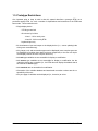
1.3. Prototype Restrictions
One important point to keep in mind is that this manual describes a prototype RTM, not a
production-quality RTM. As such, a number of simplifications and restrictions to the RTM have
been made. These restrictions are:
• Single display device
•
VT100 type terminal
•
80 columns by 24 lines
• lines 1 - 19 for use by user
• lines 20 - 24 for use by RTM
•
keyboard input only
• No simultaneous input and output to the display device (i.e., screen updating halts
during user command entry).
• Only integer, real, and enumeration types can be displayed (more complex types can
be displayed by breaking them down into these components, or the user can implement display routines for more complex structures).
• Ada task type variables are not accessible for display or modification.
• Ada access type variables are not accessible for display or modification, but the
underlying objects are accessible (i.e., the RTM does not display the address that is
the value of an access type).
• Ada constants are not accessible for modification.
• Generation of the variable database and associated conversion routines are the responsibility of the user.
• Only one page of variables can be displayed (i.e., be active) at a time.
4
CMU/SEI-87-TR-37
2. Selecting Ada Variables
Selection of Ada variables (objects) for page definition or variable manipulation purposes is accomplished by specifying the full Ada variable name2 using dot notation, which represents the
object of interest. For example, an Ada variable process_controlling_parameter in a package
Controller_A which is "withed" by the main procedure Real_Time_Application would be specified as follows:
Real_Time_Application.Controller_A.process_controlling_parameter
All Ada variables referenced by the user are checked for existence in the variable database
when:
• a START command is issued
• a CHECK command is issued
• a READ command is issued
• a SET command is issued
This checking is done by attempting to locate the variable in the variable database. If a variable
cannot be found in the database, an error message is issued in all cases. If this happens when
processing a READ or SET command, the command is ignored. If this happens in a START
command, the variable is deleted from the display page, but any legal variables on the page will
be processed normally.
2
No shorthand notation is available in the prototype RTM.
CMU/SEI-87-TR-37
5
6
CMU/SEI-87-TR-37
3. Variable Manipulation
The user can interactively view and modify data on an individual variable basis. This is done
using the following commands:
READ
Reads the current value of the specified Ada variable and displays it on the
user’s terminal.
SET
Replaces the current value of the user-specified Ada variable with the userspecified value.
The values displayed will reflect the type of Ada variable, and similarly, the value expected for
input must reflect the type of Ada variable. Both of these commands perform one-time-only
operations (which is different from the START command that initiates a continuing operation).
CMU/SEI-87-TR-37
7
8
CMU/SEI-87-TR-37
4. Page Definition
The RTM provides basic page definition facilities that allow the user to define pages for data
collection purposes (i.e., a page to be monitored).
The user creates and modifies pages by using the EDIT command. All page editing is done via a
forms management system that allows the user to move around the screen using cursor keys and
to define the variables on the page using the keypad. Additional detailed information on how
editing a page/form is accomplished can be found in the User’s Manual for a Form Generator
System in Ada [Texas Instruments 85a]. What follows is a brief overview of the process and a
detailing of the conventions expected by the RTM.
A page, as discussed earlier, is a collection of variables that are read and displayed as a group.
The creation of this group is done by the forms management system. This system views each
page as a form, and on that form are fields (which the RTM treats as variable names). Thus, the
creation of a page consists of creating a new form (page) and defining the fields (variables) that
will reside on that form (page).
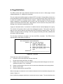
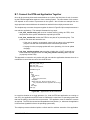
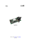
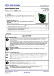
The first step in defining a new page is to issue the EDIT(); command. The RTM will then
respond with the menu shown in Figure 4-1.
The Interactive Form Generator
Choose "one" of the following:
C - create a new form
L - load an external form
E - edit the current form
M - modify the form’s attributes
S - save the current form
Q - quit
Selection: _____________________________
Figure 4-1: Edit Menu
These options are rather self explanatory:
C
Creates a new form and puts the user into edit mode.
L
Recalls a previously saved form for editing.
E
Edits the form currently in memory (useful for making incremental changes to a form and
available only after a C or L command).
M
Edits the characteristics of the form, such as row/column dimensions and screen position.
S
Stores a form on disk.
Q
Exits the editing session (not the RTM).
When a new page is created, the user is asked to determine the form’s attributes using the menu
shown in Figure 4-2.
Here is where the prototype restrictions on screen size have an impact. The user should not (the
CMU/SEI-87-TR-37
9
Form Size
Rows:
Form Position Row:
Clear Screen Option:
__________ Columns: __________
__________ Column: __________
__________ (Yes, No)
Figure 4-2: Form Attributes Menu
RTM cannot enforce this, that is why it is a convention) define a form that overlaps lines 20
through 24, which are reserved by the RTM.
Once the form/page attributes are set (which can be changed later using the M option above), a
completely blank page is presented to the user. The user is now free to move about the screen
using the cursor keys. Text can now be typed anywhere on the screen. This text will form the
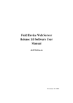
trim for the page, but does not constitute a variable. To place a variable on the screen, the user
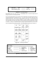
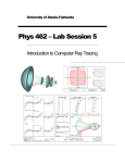
must position the cursor where the variable is to be placed and using the keypad shown in Figure
4-3, enter a 7. (There is a complete discussion of all the keypad commands in the Forms Generator User’s Manual [Texas Instruments 85a].) The RTM responds with the menu in Figure 4-4.
+-------+-------+-------+-------+
| PF1 | PF2 | PF3 | PF4 |
|
|
| Exit | Delete|
|Command| Help | Form | Line |
+-------+-------+-------+-------+
|
7
|
8
|
9
|
|
Create| Modify| Delete| Delete|
| Field | Field | Field | Eoln |
+-------+-------+-------+-------+
|
4
|
5
|
6
|
,
|
| Copy | Move |
| Delete|
| Field | Field |
| Char |
+-------+-------+-------+-------+
|
1
|
2
|
3
|
|
| Copy | Move |
| Enter |
| Line | Line |
|
|
+-------+-------+-------+ Accept|
| 0
|
.
| Form |
| Insert
| Insert|
|
| Line
| Char |
|
+---------------+-------+-------+
Figure 4-3: VT100 Keypad Definition
Field name: ______________________________________________
Field length: ____________________________________________
Character:
____________ (1 - alphabetic,
2 - numeric
limits
3 - alphanumeric,
4 - not limited)
Display:
____________ (1 - normal
2 - secondary
rendition
3 - reverse
4 - underline)
Field mode:
____________ (1 - input/output
2 - output only)
Initial value: ___________________________________________
Figure 4-4: Field Definition Menu
10
CMU/SEI-87-TR-37
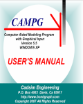
What the RTM expects the user to enter in these fields is shown in Figure 4-5.
Field name:
Field length:
Character
limits:
Display
rendition:
Field mode:
Initial value:
full Ada path name of variable
display size, in characters, of object
4
user’s choice
2
not used
Figure 4-5: Field Definition Conventions
The user can create as many or as few fields as will fit into the 19 lines available. When all the
variables are entered as fields, the field definition mode is terminated by entering a PF3 from the
keypad, at which point the main editing menu is presented again. At this point, the user must
explicitly save the page by issuing the S command shown in Figure 4-1 and supply a name for
the page. Once saved, the page is available for later use by the RTM for display purposes or
subsequent modification by editing.
A command closely related to EDIT is CHECK. Since the forms management system has no
direct knowledge of the variable database maintained by the RTM, the CHECK command should
be used after editing a page to insure that all the variables defined on the page are accessible to
the RTM.
These two commands also allow pages to be created and checked off line, i.e., without an executing application. This allows the time-consuming page editing operation to take place prior to
using the RTM to debug or tune an application. It can also save CPU time in those cases where
the RTM and the application are required to share a CPU, or where the RTM is rapidly updating
the display.
CMU/SEI-87-TR-37
11
12
CMU/SEI-87-TR-37
5. Page Management
The capabilities for managing all the pages defined by the user are split between the forms
management system discussed previously and the host computer operating system. The basic
capabilities of page management are:
Page Operation Method
Copy
This can be done two ways:
• via the forms management system by loading using the L option,
editing the form, and then storing the form (using the S option)
under a new name
• via the operating system by using the a copy command (like copy
on VMS systems or cp on UNIX systems)
Delete
This is done by simply deleting the appropriate page at the operating system
level. Neither the RTM nor the forms management system imposes any
form/page naming conventions on the user, so it is incumbent upon the user to
keep track of page names. Perhaps the easiest solution to organizing pages
is to create a page directory, and always execute the RTM from that directory.
Directory
Again, this is handled at the operation system level and it is the user’s responsibility to know the difference between page file names and any other file
names in the directory.
CMU/SEI-87-TR-37
13
14
CMU/SEI-87-TR-37
6. Page Control
Once the user has created a page that specifies Ada variables for data collection purposes, the
page can be activated for display purposes using the START command. The data collection and
screen refresh both take place at the update rate specified in the command. Once the START
command is issued, data collection and displaying take place automatically, without user intervention. The START also places the terminal into an asynchronous input mode. The normal
mode of input is for the RTM> prompt to be available to the user all times, but when a page is
actively being displayed, this interferes with output of data. To alleviate this problem, no prompt
is presented to the user. This does not mean that the user has lost control of the RTM; the user
simply has to hit any key and the RTM> prompt will appear and a command can be entered.
This also accomplishes a hold/resume option for page updating. While the RTM is waiting for the
user to enter a command, no updates are being done to the screen. Once a command is entered
and processed, updating of the screen resumes (assuming the page was not terminated, which
we discuss below). Thus, a hold (cease updating) is a return, and a resume (restart updating) is
a second return.
Once a page is no longer needed on the display, it can be terminated using a STOP command.
This removes the page from the display, terminates collection of the data from the variables
specified on the page, and returns the RTM to normal input mode (since only one page can be
active in the prototype).
CMU/SEI-87-TR-37
15
16
CMU/SEI-87-TR-37
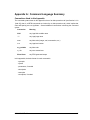
Appendix A: Command Language Summary
Conventions Used in this Appendix
The command syntax shown in this appendix is that of an Ada procedure call (see Section 6.4 in
[Ada 83]); that is, all RTM commands are invoked by an Ada procedure call, which implies that
case and spacing are not significant. Several additional conventions in defining the command
syntax:
Convention
Meaning
####
any legal Ada variable name
****
any legal page name
nnnn
any Ada value (integer, real, enumeration, etc.)
x.xx
any legal real number
my_variable
any Ada code
x.y.foo
any user-entered text
Enter Data>
any RTM generated output
In this appendix, the basic format for each command is:
• synopsis
• syntax
• parameters, if needed
• description
• examples
• exceptions, if needed
CMU/SEI-87-TR-37
17
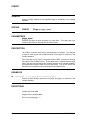
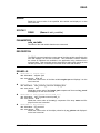
CHECK
CHECK
Checks the Ada variables on the specified page for availability in the variable
database.
SYNTAX
CHECK
(Page => page_spec);
PARAMETERS
page_spec
Specifies the page on which checking is to take place. This page_spec may
include a path name for the page file (as shown below).
DESCRIPTION
The CHECK command retrieves the specified page for analysis. This analysis
consists of checking the Ada variables defined on the page for existence in the
variable database.
This command can be used in conjunction with the EDIT command to develop
the pages of Ada variables off line. These pages can be created using the page
editor, and then checked against the variables available in the variable database,
with appropriate changes made using the page editor. This off-line activity will
allow the user to prepare for the monitoring process ahead of time.
EXAMPLES
❶
Check(Page => [rtm.page_definition]test_page);
Checks the Ada variables specified on the page, test_page, for existence in the
variable database.
EXCEPTIONS
Variable not found: ####
Illegal mode for variable: ####
Error in accessing page: ****
18
CMU/SEI-87-TR-37
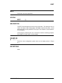
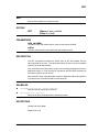
EDIT
EDIT
Places the user in the page editor.
SYNTAX
EDIT
( );
DESCRIPTION
The EDIT command places the user into the page editor. This allows the user to
create new pages, load existing pages, edit pages, and save the edits. It also
allows the user to modify attributes of the page. See Chapter 4, Page Definition,
for more details.
Once a page is created by the user, it can then be used for monitoring purposes.
See Chapter 6, Page Control, for more details.
EXAMPLES
❶
Edit();
Places the forms management system menu on the display (shown in Figure
4-1.)
EXCEPTIONS
None.
CMU/SEI-87-TR-37
19
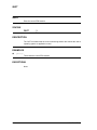
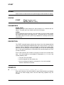
QUIT
QUIT
Exits the current RTM session.
SYNTAX
QUIT
( );
DESCRIPTION
The QUIT command exits the current monitoring session and returns the user to
operating system or application control.
EXAMPLES
❶
Quit();
Terminates the current RTM session.
EXCEPTIONS
None.
20
CMU/SEI-87-TR-37
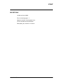
READ
READ
Reads the current value of the specified Ada variable and displays it on the
user’s terminal.
SYNTAX
READ
(Name => ada_variable);
PARAMETERS
ada_variable
The name of the Ada variable that the user wants read.
DESCRIPTION
The READ command reads the current state of the Ada variable specified by the
user and displays it on the user’s terminal. This command is used to examine
the values of individual Ada variables in the application being monitored on a
one-time basis. This command can be issued before and/or after setting an Ada
variable (see the SET command) to check the value of the Ada variable.
EXAMPLES
❶
Read(Name => engine.rpm);
The Variable: engine.rpm
has the value: 6032.24
Reads the current value of the Ada variable engine.rpm and displays it on the
user’s terminal.
❷
Read(Name => test_stub.my_record.integer_part);
The Variable: test_stub.my_record.integer_part
has the value: 194
Reads the current value of the integer_part component of the record my_record
and displays it on the user’s terminal.
❸
Read(Name => fuel_system.status(tank_1));
The Variable: fuel_system.status(tank_1)
has the value: full
Reads the current value of the tank_1 component of the array status and displays it on the user’s terminal.
❹
Read(Name => my_pointer);
The Variable: my_pointer
has the value: 1657
Reads the current value of the object pointed at by my_pointer and displays it
on the user’s terminal.
CMU/SEI-87-TR-37
21
READ
EXCEPTIONS
Variable not found: ####
22
CMU/SEI-87-TR-37
SET
SET
Sets the Ada variable to the specified value.
SYNTAX
SET
(Name => ada_variable,
Value => value);
PARAMETERS
ada_variable
The name of the Ada variable whose value the user wants modified.
value
The new value which the user wishes the Ada variable to have.
DESCRIPTION
The SET command overwrites the current value of the Ada variable with the
value specified by the user. The value specified by the user must be compatible
with the type of the Ada variable.
This command can be issued to set up process-controlling parameters before the
application begins, or it can be used in conjunction with the READ command to
fine-tune the system as it is running.
Note: Since the state of the application cannot be determined when the operation
is performed, this command should be used cautiously.
EXAMPLES
❶
Set(Name=>engine.rpm<, Value=>4000.00);
Sets the value of engine.rpm to 4000.00.
❷
Set(engine.rpm, 4000.00);
Same as the above example without named association.
EXCEPTIONS
Variable not found: ####
Illegal value: nnnn
CMU/SEI-87-TR-37
23
START
START
Starts collection of data based on the specified page of Ada variables for display.
SYNTAX
START
(Page => page_spec,
Update_Rate => value);
PARAMETERS
page_spec
Specifies the page which identifies the Ada variables to be collected and displayed. The page_spec may contain a path name to the page.
value
Optional parameter which specifies, as a real number, the rate at which the data
are collected and written to the display device. The default value is 2.0 seconds.
The usable range is from 0.01 (once every hundredth of a second) to 60.0 (once
every minute).
DESCRIPTION
The START command begins collecting the values of the Ada variables defined
on the user-specified page and displays them on the user’s terminal. The rate at
which the data are displayed is user controllable by specifying the Update_Rate
parameter (in the prototype, the display update_rate is also the data sampling
rate). If this optional parameter is not specified, then a default update rate of two
seconds is assumed.
Prior to data collection each variable on the page is located in the variable database. If an Ada variable is not available for examination (i.e., it is not in the
variable database), then:
1. The value is not accessible
2. It will be dropped from the collection list
3. An error message will appear on the page (i.e., the user’s terminal)
where the data was to be placed.
EXAMPLES
❶
24
Start(Page => EngineVariables, Update_Rate => 0.2);
Starts data collection of the Ada variables on page EngineVariables and displays
them on the default display device with the data being updated every 0.2
seconds.
CMU/SEI-87-TR-37
START
EXCEPTIONS
Variable not found: ####
Error in accessing page: ****
Maximum number of active pages in use.
STOP command must be issued first.
Bad update_rate, reenter in x.xx format
CMU/SEI-87-TR-37
25
STOP
STOP
Stop data collection and display of the named page.
SYNTAX
STOP
(Page => page_spec);
PARAMETERS
page_spec
Specifies the page on which data collection is currently taking place.
DESCRIPTION
The STOP command terminates the collection of data based on a page which is
actively collecting data for display and removes the page from the screen.
EXAMPLES
❶
Stop(control_parameters);
Stops data collection of the Ada variables on the page control_parameters
(assuming a START command for the page has been previously issued).
EXCEPTIONS
Page not currently active: ****
No active pages
26
CMU/SEI-87-TR-37
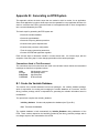
Appendix B: Generating an RTM System
This appendix outlines the basic steps that are needed to build a monitor for an application.
Since each application is unique, these steps must be repeated for every application because it is
easier to customize the RTM to meet the needs of each application than to force the application
into a set mold dictated by the RTM.
The basic steps for generating the RTM system are:
• Create the variable database.
• Create the type database.
• Create the compute_address procedure.
• Customize the system dependencies.
• Customize the processor configuration.
• Tune the system generation parameters.
• Connect the RTM and application together.
Each of these steps is discussed in detail in its own section later. All of these steps, with the
exception of the tuning step, involve changing the bodies of the various packages.
Conventions Used in This Document
The conventions used in this document are listed in the left-hand column below; their associated
meanings are listed in the right-hand column.
code
package
subsystem
COMMAND
Ada language construct
Ada package name
Ada subsystem
RTM command
B.1. Create the Variable Database
The creation of the variable database involves two packages: the variable_database package,
which is responsible for creating and managing the variable database as a structure, and the
library_interface package, which is responsible for generating the variable information stored in
the database.
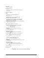
Two procedures comprise the variable_database:
initialize_database: Creates and populates the database (see Figure B-1).
find: Traverses the database.
The variable database is built automatically by initialize_Database during elaboration of the
RTM. These routines depend on the interface provided by the library_interface package and do
not change as part of the customization of the RTM.
CMU/SEI-87-TR-37
27
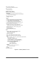
with Unchecked_Deallocation;
-- Use the service "unchecked_deallocation."
-with Types_Manager;
-- Use the service "find."
-separate (Variable_Database)
procedure Initialize_Database is
--|*****************************************************************
--| Description:
--| This module is responsible for building the variable database
--| by whatever means are available.
--|
--| Parameter Description:
--| none
--|
--| Notes:
--| All of the system dependent issues related to obtaining
--| data object addresses have be isolated in these packages:
--|
Library_interface: for static data information.
--|
Address_generator: for dynamic data information.
--| These are the packages that must be changed to reflect the
--| system configuration and environment.
--|*****************************************************************
procedure Free is new Unchecked_Deallocation
(Library_Interface.Variable_Representation,The_Variable);
Variable_Position: Library_Interface.Variable_Iterator;
Node_Root: Db.Tree;
Found_Variable: Boolean;
The_Next_Variable: The_Variable;
begin
--- The basic operation is the same for all the variables:
-Build a variable_representation record.
-Insert the record into the tree.
-- Repeat for all variables.
-Library_Interface.Make_Iterator(Variable_Position);
while Library_Interface.More(Variable_Position) loop
begin
The_Next_Variable := new Library_Interface.Variable_Representation;
Library_Interface.Get_Next
(The_Iterator => Variable_Position,
Variable_Information => The_Next_Variable.all );
The_Next_Variable.Data_Type := Types_Manager.Find
(Name => The_Next_Variable.Variable_Type);
Db.Insertnode(N => The_Next_Variable,
T => Variable_Database,
Root => Node_Root,
Exists => Found_Variable);
exception
when Types_Manager.Type_Not_Found =>
Free (The_Next_Variable);
end ;
end loop ;
end Initialize_Database;
Figure B-1: Initialize_Database Procedure
28
CMU/SEI-87-TR-37
The library_interface is responsible for supplying the information needed by the RTM. This information, as a minimum, consists of:
variable_name: The full Ada path name of the variable. This path name must go to the
record component level if such a variable is to be available for monitoring.
base_address: The static address of the variable in application memory.
type_name: The name of the data type used in the variable declaration. This name must
match the character string used to identify the type in the types_manager package (see
Section B.2).
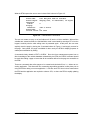
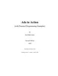
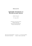
The manner in which this information is generated is irrelevant to the RTM. To illustrate how the
library_interface package is used, the code for initialize_database is shown in Figure B-1. In
words, Figure B-1 embodies using the library_interface to build the database; these steps are:
1. Make an iterator (using make_iterator).
2. While there are more variables to process (indicated by a true value for more loop):
a. get the next variable information (variable_representation of the next variable, using get_next)
b. get the type of the variable (using find)
c. insert the variable into the variable database
This simple algorithm describes the entire process of building the variable database and illustrates that the variable_database knows nothing about the data in the structure or about how
the data are generated. Its only concern is that the information is supplied using the interface:
variable_representation: Type that supplies the variable information (outlined above)
plus any miscellaneous information needed (or available).
make_iterator: Responsible for doing all the preparation necessary to generate variable
information. It then returns an iteration control variable which is used by get_next to select
the next variable to generate information on and by more to determine if all of the available
variable information has been retrieved. This variable is private to the library_interface
package and has no significance outside the body of the package; therefore it can be used
to represent anything the library_interface needs internally to collect the variable information.
get_next: Takes the iteration variable and generates a variable_representation record.
The manner in which this is accomplished is irrelevant to the RTM. The existing version
uses standard Ada facilities and is based on the assumption that the system is executing
on one processor. For a two-CPU configuration, some kind of parsing of an address map
would have to be substituted for this body. There is no order implied by the manner in
which variables are returned; the variable_database package simply builds the structure to
tie all the data together.
CMU/SEI-87-TR-37
29
More: takes the iteration variable and returns a true value when more variables are available and a false value when all the variables have been processed. Again, the exact
nature of how this is determined is dependent on how the variable information is generated.
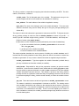
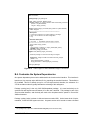
The approach used in the prototype is applicable only to a single processor configuration. In this
approach, the library_interface "withs" in all the packages of interest to the user. The package
then lists all the variables visible along with their Ada data types; the ’address3 attribute is then
used to return the address of the variable (as an integer). The code that implements the
library_interface package for this case is shown in Figure B-2.4 Clearly, this approach has some
severe restrictions:
• Only package-level objects can be monitored (no local or package-body data are
visible).
• It does not work in a multiple processor system.
• Every item to monitor must be placed in the database by hand; this implies that all
record components and array references must be expanded (which creates an unnecessarily large database).
A number of other solutions to the database problem are possible, and in fact must be actively
pursued for multiple CPU systems. Something as simple as a linker load map showing where all
the static variables are allocated can be parsed and used to populate the variable database.
Clearly, a better solution (possibly the best solution) is access to the compiler and linker output
used by a symbolic debugger. The availability of this level of detailed information vastly increases the number of items that can be monitored and reduces the tedium that the prototype
approach implies.
B.2. Create the Type Database
The types_manager package contains all the type information that the RTM needs to know.
When we discuss types, we are referring to the Ada data types associated with the variables in
the variable database. To be in the variable database, a variable’s declared data type must be in
the type database; without this correspondence, the RTM does not know enough about the variable to extract it from the application or display it to the user.
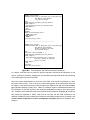
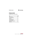
The type database is entirely constructed by hand (again, access to compiler-generated information would alleviate this problem) primarily because informing the RTM about a new type
requires program changes to the body of types_manager. The best way to illustrate the information needed by the types_manager is to examine the code fragment shown in Figure B-3.
The type information is held in two structures: valid_type_name and type_representation. The
explanation and examples shown in Figure B-3 illustrate how a type is entered into the database:
3
Care must be taken in the use of ’address attribute since it may need to be adjusted to obtain the true address of the
data.
4
30
This approach has to be entirely crafted by hand and is not the recommended approach.
CMU/SEI-87-TR-37
with System;
-- Use type "address."
-with Unchecked_Conversion;
-- Use service "unchecked_conversion."
-with Test_Stub;
-- Use data objects defined here for testing the monitor.
-package body Library_Interface is
--- Used to convert all the system addresses into integers so that
-- they can be stored in the variable database. In a system where
-- an address map is used, this routine will need to be reimplemented.
-function Get_Address is new Unchecked_Conversion
(Source => System.Address,
Target => Integer);
--|*****************************************************************
procedure Make_Iterator (The_Iterator: in out Variable_Iterator) is
begin
The_Iterator := 0;
end Make_Iterator;
--|*****************************************************************
procedure Get_Next (The_Iterator: in out Variable_Iterator;
Variable_Information: out Variable_Representation) is
begin
case The_Iterator is
when 0 =>
Variable_Information.Variable_Name(1..20) := "test_stub.my_integer";
Variable_Information.Base_Address := Get_Address(Test_Stub.My_Integer’Address);
Variable_Information.Variable_Type(1..7) := "integer";
when 1 =>
Variable_Information.Variable_Name(1..17) := "test_stub.my_real";
Variable_Information.Base_Address := Get_Address(Test_Stub.My_Real’Address);
Variable_Information.Variable_Type(1..5) := "float";
when others =>
null ;
end case ;
The_Iterator := The_Iterator + 1;
end Get_Next;
--|*****************************************************************
function More (The_Iterator: in Variable_Iterator) return Boolean is
begin
if The_Iterator <= 1 then
RETURN True;
else
RETURN False;
end if ;
end More;
end Library_Interface;
Figure B-2: Example of Generating Variable Information
CMU/SEI-87-TR-37
31
• An enumeration name for the type is created (in valid_type_name).
• A representation record for the type is created (in type_representation).
• A string name is defined for the type in the package body (this is the name returned
by library_interface).
The only restriction on types is that enumeration types (from the application being monitored)
must be declared in the body of package types_manager; this can be done by "withing" in the
package that declares the type or by manually redefining the type. This restriction does not apply
to integers and floats, since they are universal base types.
Once the type is defined, the generic conversion routine for the base type must be instantiated for
the new type (the convert_integers generic is shown in Figure B-4). The generic is instantiated
with the source type (a type that the RTM understands), a default display width, and a low-level
conversion procedure (shown in Figure B-5). After instantiation, integer bit strings can be converted to display strings by reference to rtm_integers.make_string (shown in Figure B-6), or a
string can be converted to a bit string by using rtm_integers.make_value (also shown in Figure
B-6). The complete version of the case statements shown in Figure B-6 contains an entry for
every type defined in valid_type_name and invokes the generic instantiation appropriate for
each type.
Finally, the default_integer_conversion procedure shown in Figure B-5 is critical for proper
multi-CPU processing. In a single CPU system, the approach shown in Figure B-5 is correct —
that is, take an address and return the integer at that address. In a multi-CPU system, this may
not be correct, especially when the underlying type representation is different between the RTM
processor and the application processor(s). This situation requires the conversion routine to map
the target (application processor) bit representation into the host (RTM processor) bit representation. It is the responsibility of this low-level function to supply the generic conversion package
with a bit representation it understands.
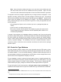
B.3. Create the Compute_Address Procedure
The compute_address procedure is an important abstraction for the system since it combines
the information from the variable_database and the types_manager to generate effective addresses for variables. In the simple case used by the prototype (shown in Figure B-7), address
computation simply requires that the variable be located in the variable database and its base
address returned (since every available variable and its base address are in the database). In a
more sophisticated case, where a debugger interface is available or a more powerful parser is
used (implying that address offsets are computed), the compute_address procedure can be
modified to accommodate this without impacting the RTM code. This isolation of address computation allows for more powerful methods to be incorporated as they become available.
32
CMU/SEI-87-TR-37
with Test_Stub;
package body Types_Manager is
--- Define the names of all the legal types.
-type Valid_Type_Name is (Integers, Floats, Rtm_Enum1, Rtm_Record);
--- Define all the data needed about each type:
-type_name_as_string -> A character string version of the type name.
-This must match exactly with the type as it
-exists in the application program, where the
-type_name is a convenient enumeration literal
-for this type.
-type_name -> An enumeration literal for the type.
-type_length -> The size of the type in smallest_units.
-display_width -> Number of characters needed to display a value
-of the type: integer := 25;
-indirection_level -> An integer that indicates how many levels of
-indirect access the type represents.
-type Type_Representation is record
Type_Name_As_String: String(1..256);
Type_Name: Valid_Type_Name;
Type_Length: Integer := 0;
Display_Width: Integer := 25;
Indirection_Level: Integer := 0;
end record ;
--- Define the table that holds all the type information; define
-- type_name_as_string in body.
-Number_Of_Valid_Types: Valid_Rtm_Type := 4;
Valid_Rtm_Types: array (1..Number_Of_Valid_Types) of Type_Representation :=
((Type_Name_As_String => (others => ’ ’),
Type_Name => Integers, Type_Length => 1,
Display_Width => 10,Indirection_Level => 0),
(Type_Name_As_String => (others => ’ ’),
Type_Name => Floats, Type_Length => 1,
Display_Width => 10,Indirection_Level => 0),
(Type_Name_As_String => (others => ’ ’),
Type_Name => Rtm_Enum1, Type_Length => 1,
Display_Width => 5,Indirection_Level => 0),
(Type_Name_As_String => (others => ’ ’),
Type_Name => Rtm_Record, Type_Length => 2,
Display_Width => 20,Indirection_Level => 0));
--|*****************************************************************
--|
--| Package Body
--|
--| The body is responsible for initializing the string versions
--| of all the type names.
--|
--|*****************************************************************
begin
Valid_Rtm_Types(1).Type_Name_As_String(1..7) := "integer";
Valid_Rtm_Types(2).Type_Name_As_String(1..5) := "float";
Valid_Rtm_Types(3).Type_Name_As_String(1..9) := "rtm_enum1";
Valid_Rtm_Types(4).Type_Name_As_String(1..10) := "rtm_record";
end Types_Manager;
Figure B-3: Code Fragment That Defines a Type Database Entry
CMU/SEI-87-TR-37
33
with System;
-- Need the type "Address."
-package Conversions is
--- Signals that the value in the character string is the wrong type
-- for the variable.
-Illegal_Value: exception ;
generic
--- Default Width of the generated character strings.
Width: Positive := 15;
--- Integer type source, This is the host machine’s type.
type Source_Representation is range <>;
--- Low-level conversion routine needed to convert from the target
-- representation to the host representation of the source type.
-- (referred to as source_representation)
with function Target_Conversion (Raw_Value: in System.Address)
return Source_Representation;
package generic package Convert_Integers is
procedure Make_String (Raw_Value: in System.Address;
Field_Size: in Integer;
Value: out String);
--|*****************************************************************
--| Description:
--| Make_string takes a binary bit string and converts it into
--| an integer character string.
--|
--| Parameter Description:
--| raw_value -> The address of the binary bit string to be
--|
converted.
--| field_size -> The number of characters needed in the output
--|
string.
--| value -> The character image of the binary bit string as
--|
an integer.
--|*****************************************************************
procedure Make_Value (Raw_Value: in String;
Value: in System.Address);
--|*****************************************************************
--| Description:
--| Make_value takes an integer character string and converts it into a
--| binary bit string.
--|
--| Parameter Description:
--| raw_value -> The character string to be converted.
--| value -> The address where the resulting bit string is to be
--|
stored.
--|*****************************************************************
end Convert_Integers;
end Conversions;
Figure B-4: Generic Conversion Package for Integers
34
CMU/SEI-87-TR-37
with Conversions;
package body Types_Manager is
type Integer_Pointer is access Integer;
function Address_To_Integer_Pointer is new Unchecked_Conversion
(Source => System.Address,
Target => Integer_Pointer);
function Default_Integer_Conversion (Raw_Value: in System.Address)
return Integer is
--|*****************************************************************
--| Description:
--| Convert from a bit string at a system address to an integer
--| value. This is valid for a one-CPU configuration
--| only.
--|
--| Parameter Description:
--| raw_value -> The address of the bit string to convert.
--|*****************************************************************
Value_Pointer: Integer_Pointer;
begin
Value_Pointer := Address_To_Integer_Pointer(Raw_Value);
RETURN Value_Pointer.all ;
end Default_Integer_Conversion;
pragma Inline (Default_Integer_Conversion);
--- Create the package to convert from bit strings to integers.
-package Rtm_Integers is new Conversions.Convert_Integers
(Width => 15,
Source_Representation => Integer,
Target_Conversion => Default_Integer_Conversion);
end Types_Manager;
Figure B-5: Code Fragment That Instantiates Integer Conversions
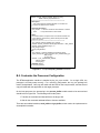
B.4. Customize the System Dependencies
One system dependency that must be addressed is the virtual terminal interface. This interface is
based on a UNIX termcap style definition file for controlling the terminal functions. This definition
file is tcf.tcf. This file is already set up for a VT100 style terminal; therefore, the existence of a
VT100 emulation mode will greatly facilitate the rehosting of this subsystem.
Package sysdep_body is the only VAX VMS-dependent package. It is used exclusively to do
synchronous and asynchronous character I/O to the user’s terminal. This package is part of the
virtual terminal interface, and the body will need to be reimplemented to operate in a non-VAX
VMS environment.
Package sysdep_body5 is written in Ada and executes under VMS. At the lowest level of implementation, it uses the VMS system services. A system service call is issued to create a channel
5
This package boby is part of the virtual terminal subsystem [Texas Instruments 85b].
CMU/SEI-87-TR-37
35
separate (Types_Manager)
procedure Convert_String_To_Value (Data_Type: in Valid_Rtm_Type;
Raw_Data: in System.Address;
The_Value: in String) is
begin
case Valid_Rtm_Types(Data_Type).Type_Name is
when Integers =>
Rtm_Integers.Make_Value (The_Value,Raw_Data);
when others =>
null ;
end case ;
exception
when Conversions.Illegal_Value =>
RAISE Illegal_Value;
when others =>
RAISE ;
end Convert_String_To_Value;
----------------------------------------------------------------------------separate (Types_Manager)
procedure Convert_Value_To_String (Data_Type: in Valid_Rtm_Type;
Raw_Data: in System.Address;
Number_Of_Characters: in Integer;
The_Value: out String) is
begin
The_Value := (The_Value’range => ’ ’);
case Valid_Rtm_Types(Data_Type).Type_Name is
when Integers =>
Rtm_Integers.Make_String (Raw_Value => Raw_Data,
Field_Size => Number_Of_Characters,
Value => The_Value);
when others =>
null ;
end case ;
end Convert_Value_To_String;
Figure B-6: Code Fragment That Performs Integer Conversions
to a device, and QIO calls are issued to perform character read and write operations on the
device. Starlet and Condition_Handling are VAX Ada library packages that allow easy interfacing
of the VMS system services to the RTM.
Since the system dependencies are all tied to VAX VMS, a few words on rehosting to a UNIX
environment are in order. First, to rehost to a UNIX-based system, all the QIO system calls must
be replaced. UNIX-equivalent system calls will replace the VMS service calls in procedures open,
get, and put of package sysdep_body. VMS’s I/O channels might be considered equivalent to a
File Descriptor in UNIX with access to the keyboard established by using the UNIX open system
call. Character level reads and writes to the terminal can be performed using text_io procedures
after setting the keyboard to "RAW" mode (via an ioctl call); this will allow characters to be
obtained unedited from the keyboard driver without a terminating carriage return (or newline); the
virtual terminal subsystem and forms management subsystem perform all character interpretation.
36
CMU/SEI-87-TR-37
function Compute_Address (Variable_Name: in String)
return Address_Representation is
--|*****************************************************************
--| Description:
--| This module takes the database identifier of a variable and
--| computes the address of the variable.
--|
--| Parameter Description:
--| the_variable -> Name of variable for which address is needed.
--| return
-> Computed address of the variable.
--|
--| Notes:
--| No address offset is computed since all accessible variables are
--| in the database, and the base_address already has the offset
--| taken into account.
--|*****************************************************************
The_Variable: Variable_Database.The_Variable;
Address: Address_Generator.Address_Representation := Null_Address;
Address_Offset: constant Integer := 0;
Data_Length: Integer;
Access_Flag: Boolean;
begin
The_Variable := Variable_Database.Find(Variable_Name);
Types_Manager.Get_Type_Information (The_Variable.Data_Type,
Data_Length,
Access_Flag);
Address := (The_Variable.Base_Address,
Address_Offset,
Access_Flag);
RETURN Address;
end Compute_Address;
Figure B-7: Simple Compute_Address Procedure
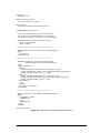
B.5. Customize the Processor Configuration
The RTM-to-application interface is handled by the rtm_core module. On a single CPU, the
prototype is currently setup correctly. For a two-CPU configuration, the rtm_core package will
need to be duplicated. One copy will reside with the RTM on the host processor, and the second
copy will reside with the application on the target processor.
On the host processor, the processing in the process_buffer module needs to be removed and
should look like Figure B-8. The following need to take place:
1. Transfer the command and data buffers to the target, and
2. Wait for the command and data buffers to become available.
There are two stubbed modules, send_buffer and get_buffer, which need to be implemented to
accomplish this transfer.
CMU/SEI-87-TR-37
37
On the target processor, the process_buffer module needs to be integrated into the top-level
executive or the timing controller of the application. It is then given an execution time-slice
periodically. During this time-slice it will:
1. Look for the availability of a command buffer.
2. Process all the commands in the buffer (this is why the core_buffer_size
parameter is so critical: it controls the maximum amount of time the rtm_core will
ever use to execute).
3. Mark the buffer as available and transfer it back to the host.
Again, the send_buffer and get_buffer modules must be implemented to correctly complete
transferring the buffers between the processors (which is not a trivial exercise).
procedure Process_Buffer is
begin
--- Send the command and data buffers to the rtm_core and wait
-- for their return.
-Get_Buffer;
Send_Buffer;
end Process_Buffer;
Figure B-8: Process_Buffer Procedure for Two CPUs
B.6. Tune the System Generation Parameters
The parameters available for tailoring the RTM to suit the local environment are contained in the
package sysgen. They are:
smallest_unit: The type which represents the smallest addressable or most efficiently
addressable unit on the target processor. All type sizes (discussed in Section B.2) are
defined in terms of this unit. For example, on the VAX running VMS, the most efficient
addressable unit is a 32-bit word or the standard integer; thus all types in the RTM type
database are defined as multiples of this 32-bit "smallest unit."
core_buffer_size: The size of the command and data buffers that communicate between
the RTM and the rtm_core (which resides in the target processor along with the
application). This limits the number of deposit and extract operations that the rtm_core can
process during a time-slice and should be tailored to reflect the minimum time-slice that the
rtm_core will have available.
processor_count: The number of processors being used in the system. It is either one or
two (a two implies that the work discussed in the Section B.5 must be implemented).
default_rtm_device: The default disk directory where the RTM will look for page files,
unless an explicit path name is supplied.
38
CMU/SEI-87-TR-37
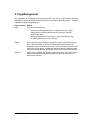
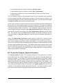
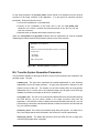
B.7. Connect the RTM and Application Together
Once all the previously discussed customizations are in place, the final piece of work is connecting the RTM and application together to form a working system. The exact nature of this connection depends on the number of processors in the system. We will show an example from the
single processor case and discuss the extensions needed for the multiple processor case.
The simplest way to connect the system together is shown in Figure B-9 (this example assumes a
non-real-time application). This example illustrates the key steps:
1. real_time_monitor.setup_rtm must be invoked before invoking the RTM, since
this performs all the system initializations required by the RTM.
2. real_time_monitor.rtm invokes the RTM for one pass of its processing loop. Two
points to note about this interaction are:
• If the user is entering a command, control will not return to the application
program until after the command has been entered and processed.
• If a page is active, one page update will occur (assuming it is time to update
the page).
3. real_time_monitor.terminate_rtm exception signals that a QUIT command has
been issued and indicates that a call real_time_monitor.closeout_rtm is required
(to properly exit the RTM).
This approach to connection only works well with non-real-time applications because there is no
mechanism to control the amount of time the RTM uses.
with Text_Io;use Text_Io;
with Test_Stub;
with Real_Time_Monitor;
procedure Appl is
begin
loop
Test_Stub.Go;
begin
Real_Time_Monitor.Rtm;
exception
when Real_Time_Monitor.Terminate_Rtm =>
Put_Line("RTM terminated, application still running");
end ;
end loop ;
end Appl;
Figure B-9: Application to RTM Connection
In a real-time situation on a single processor (i.e., both the RTM and application are running on
one CPU), the application and RTM must be individually invoked from an operating system task
that has the ability to time-slice the two processes. The application must be allowed to execute
as required. The RTM is executed and suspended as time permits (i.e., whenever the application
is idle and has signaled this fact to the operating system task).
The multiple processor situation implies a critical need for real-time execution of the application.
CMU/SEI-87-TR-37
39
In many respects this is the simplest case. In this situation, the RTM (modified as described in
Section B.5) can be executing on its own CPU and communicating with the application (which is
executing on one or more CPUs) over a high-speed bus. This allows everything to execute as
needed, with minimum perturbation of the application and no slow down in the RTM’s user interface.
40
CMU/SEI-87-TR-37
References
[Ada 83]
American National Standard Reference Manual for the Ada Programming
Language,
ANSI/MIL-STD-1815A-1983, 1983.
[D’Ippolito 87]
D’Ippolito, R., K. Lee, C. Plinta, M. Rissman, and R. Van Scoy.
Prototype Real-Time Monitor: Requirements.
Technical Report CMU/SEI-87-TR-36, Software Engineering Institute, November, 1987.
[Texas Instruments 85a]
User Manual for a Form Generator System in Ada.
Equipment Group - ACSL, P.O. Box 801, MS 8007, McKinney, TX 75609,
1985.
[Texas Instruments 85b]
User Manual for an ANSI X3.64 Compatible Virtual Terminal in Ada.
Equipment Group - ACSL, P.O. Box 801, MS 8007, McKinney, TX 75609,
1985.
[Van Scoy 87a]
Van Scoy, R., C. Plinta, T. Coddington, R. D’Ippolito, K. Lee, and M. Rissman.
Prototype Real-Time Monitor: Design.
Technical Report CMU/SEI-87-TR-38, Software Engineering Institute, November, 1987.
[Van Scoy 87b]
Van Scoy, R.
Prototype Real-Time Monitor: Ada Code.
Technical Report CMU/SEI-87-TR-39, Software Engineering Institute, November, 1987.
CMU/SEI-87-TR-37
41
42
CMU/SEI-87-TR-37
Index
’address 30
Access 4
Base_address 29
Case 32
Check 3, 5, 11, 18
Code 27
Command 27
Compute_address 32
Condition_Handling 36
Constant 4
Controller_A 5
Convert_integers 32
Core_buffer_size 37, 38
Default_integer_conversion 32
Default_rtm_device 38
Edit 3, 9, 11, 18, 19
Find 27, 29
Floats 32
Forms management subsystem 36
Send_buffer 37, 38
Set 3, 5, 7, 21, 23
Smallest_unit 38
Starlet 36
Start 3, 5, 7, 15, 24, 26
Stop 3, 15, 25, 26
Subsystem 27
Sysdep_body 35, 36
Sysgen 38
Task 4
Tcf.tcf 35
Text_io 36
Type_name 29
Type_representation 30, 32
Types_manager 29, 30, 32
Valid_type_name 30, 32
Variable database 5, 24
Variable_database 27, 29, 32
Variable_name 29
Variable_representation 29
Virtual terminal subsystem 36, 35
Get 36
Get_buffer 37, 38
Get_next 29
Initialize_database 27, 29
Integers 32
Library_interface 27, 29, 30, 32
Make_iterator 29
More 29
Open 36
Package 27
Process_buffer 37, 38
Process_controlling_parameter 5
Processor_count 38
Put 36
Quit 3, 20, 39
Read 3, 5, 7, 21, 23
Real_Time_Application 5
Real_time_monitor.closeout_rtm 39
Real_time_monitor.rtm 39
Real_time_monitor.setup_rtm 39
Real_time_monitor.terminate_rtm 39
Rtm_core 37, 38
Rtm_integers.make_string 32
Rtm_integers.make_value 32
CMU/SEI-87-TR-37
43
44
CMU/SEI-87-TR-37
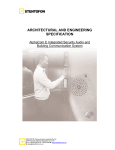
Table of Contents
1. Basic Concepts
1.1. Definitions
1.2. Command Summary
1.3. Prototype Restrictions
3
3
3
4
2. Selecting Ada Variables
5
3. Variable Manipulation
7
4. Page Definition
9
5. Page Management
13
6. Page Control
15
Appendix A. Command Language Summary
17
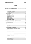
Appendix B. Generating an RTM System
B.1. Create the Variable Database
B.2. Create the Type Database
B.3. Create the Compute_Address Procedure
B.4. Customize the System Dependencies
B.5. Customize the Processor Configuration
B.6. Tune the System Generation Parameters
B.7. Connect the RTM and Application Together
27
27
30
32
35
37
38
39
References
41
Index
43
CMU/SEI-87-TR-37
i
ii
CMU/SEI-87-TR-37
List of Figures
Figure 4-1:
Figure 4-2:
Figure 4-3:
Figure 4-4:
Figure 4-5:
Figure B-1:
Figure B-2:
Figure B-3:
Figure B-4:
Figure B-5:
Figure B-6:
Figure B-7:
Figure B-8:
Figure B-9:
Edit Menu
Form Attributes Menu
VT100 Keypad Definition
Field Definition Menu
Field Definition Conventions
Initialize_Database Procedure
Example of Generating Variable Information
Code Fragment That Defines a Type Database Entry
Generic Conversion Package for Integers
Code Fragment That Instantiates Integer Conversions
Code Fragment That Performs Integer Conversions
Simple Compute_Address Procedure
Process_Buffer Procedure for Two CPUs
Application to RTM Connection
CMU/SEI-87-TR-37
9
10
10
10
11
28
31
33
34
35
36
37
38
39
iii