1
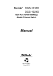
Preface
D-Link reserves the right to revise this publication and to make changes in the content hereof without obligation to notify any person or organization
of such revisions or changes.
Manual Revisions
ENGLISH
Revision
1.0
Date
February 18, 2010
1.1
May 18, 2010
Description
DGS-1005G - Hardware revision A1
Added Windows® 7 Support
Trademarks
D-Link and the D-Link logo are trademarks or registered trademarks of D-Link Corporation or its subsidiaries in the United States or other countries.
All other company or product names mentioned herein are trademarks or registered trademarks of their respective companies.
Copyright Statement
No part of this publication or documentation accompanying this product may be reproduced in any form or by any means or used to make any
derivative such as translation, transformation, or adaptation without permission from D-Link Corporation/D-Link Systems, Inc., as stipulated by the
United States Copyright Act of 1976 and any amendments thereto. Contents are subject to change without prior notice.
Copyright ©2010 by D-Link Corporation/D-Link Systems, Inc. All rights reserved.
FCC Statement
This equipment has been tested and found to comply with the limits for a Class B digital device, pursuant to Part 15 of the FCC Rules. These limits
are designed to provide reasonable protection against harmful interference when the equipment is operated in a commercial environment. This
equipment generates, uses, and can radiate radio frequency energy and, if not installed and used in accordance with this user’s guide, may cause
harmful interference to radio communications. Operation of this equipment in a residential area is likely to cause harmful interference in which
case the user will be required to correct the interference at his own expense.
2
Table of Contents
ENGLISH
Preface.............................................................................................. 2
Manual Revisions...........................................................................................2
Trademarks......................................................................................................2
Copyright Statement...................................................................................2
FCC Statement................................................................................................2
Safety Instructions.......................................................................... 4
Safety Cautions..............................................................................................4
Protecting Against Electrostatic Discharge.........................................6
Product Overview............................................................................ 7
Package Contents.........................................................................................7
Setup..................................................................................................................7
Introduction....................................................................................................7
D-Link Green Ethernet Technology...............................................7
Fast Ethernet Technology..................................................................8
Gigabit Ethernet Technology...........................................................8
Switching Technology........................................................................9
802.1p Priority Tagging......................................................................9
Jumbo Frame Support.......................................................................9
Features..........................................................................................................10
Hardware Overview....................................................................................11
Top Panel (LEDs).................................................................................11
Rear Panel (Connections)................................................................13
Installation..................................................................................... 14
Before You Connect to the Network.....................................................14
Mounting the Switch on the Wall..........................................................15
Mounting on a cement wall...........................................................15
Mounting on a wood wall...............................................................15
Connecting the Switch..............................................................................16
DGS-1005G to End Node.................................................................16
Hub/Switch to DGS-1005G.............................................................16
Connecting To Network Backbone or Server...........................16
Troubleshooting............................................................................ 17
Networking Basics......................................................................... 18
Check your IP address................................................................................18
Statically Assign an IP address................................................................19
Glossary.......................................................................................... 20
Technical Specifications................................................................ 25
RJ-45 Pin Specifications............................................................................26
Contacting Technical Support...................................................... 27
Registration................................................................................... 28
3
Safety Instructions
Use the following safety guidelines to ensure your own personal safety and to help protect your system from potential damage.
Safety Cautions
To reduce the risk of bodily injury, electrical shock, fire, and damage to the equipment, observe the following precautions.
ENGLISH
Observe and follow service markings. Do not service any product except as explained in your system documentation. Opening or removing covers
that are marked with the triangular symbol with a lightning bolt may expose you to an electrical shock. Only a trained service technician should
service components inside these compartments.
If any of the following conditions occur, unplug the product from the electrical outlet and replace the part or contact your trained service
provider:
– The power cable, extension cable, or plug is damaged.
– An object has fallen into the product.
– The product has been exposed to water.
– The product has been dropped or damaged.
– The product does not operate correctly when you follow the operating instructions.
• Keep your system away from radiators and heat sources. Also, do not block cooling vents.
• Do not spill food or liquids on your system components, and never operate the product in a wet environment. If the system gets
wet, see the appropriate section in your troubleshooting guide or contact your trained service provider.
• Do not push any objects into the openings of your system. Doing so can cause a fire or an electric shock by shorting out interior
components.
• Use the product only with approved equipment.
• Allow the product to cool before removing covers or touching internal components.
• Operate the product only from the type of external power source indicated on the electrical ratings label. If you are not sure of
the type of power source required, consult your service provider or local power company.
4
• To help avoid damaging your system, be sure the voltage selection switch (if provided)
on the power supply is set to match the power available at your location:
– 115 volts (V)/60 hertz (Hz) in most of North and South America and some Far Eastern countries such as South Korea and Taiwan.
– 100 V/50 Hz in eastern Japan and 100 V/60 Hz in western Japan.
– 230 V/50 Hz in most of Europe, the Middle East, and the Far East.
• Also be sure that attached devices are electrically rated to operate with the power available in your location.
• Use only approved power cable(s). If you have not been provided with a power cable for your system or for any AC-powered option
intended for your system, purchase a power cable that is approved for use in your country. The power cable must be rated for the
product and for the voltage and current marked on the product’s electrical ratings label. The voltage and current rating of the
cable should be greater than the ratings marked on the product.
ENGLISH
• To help prevent an electric shock, plug the system and peripheral power cables into properly grounded electrical outlets. These
cables are equipped with three-prong plugs to help ensure proper grounding. Do not use adapter plugs or remove the grounding
prong from a cable. If you must use an extension cable, use a 3-wire cable with properly grounded plugs.
• Observe extension cable and power strip ratings. Make sure that the total ampere rating of all products plugged into the extension
cable or power strip does not exceed 80 percent of the ampere ratings limit for the extension cable or power strip.
• To help protect your system from sudden, transient increases and decreases in electrical power, use a surge suppressor, line conditioner,
or uninterruptible power supply (UPS).
• Position system cables and power cables carefully; route cables so that they cannot be stepped on or tripped over. Be sure that
nothing rests on any cables.
• Do not modify power cables or plugs. Consult a licensed electrician or your power company for site modifications. Always follow your
local/national wiring rules.
• When connecting or disconnecting power to hot-pluggable power supplies, if offered with your system, observe the following
guidelines:
– Install the power supply before connecting the power cable to the power supply.
– Unplug the power cable before removing the power supply.
– If the system has multiple sources of power, disconnect power from the system by unplugging all power cables from the power
supplies.
5
Protecting Against Electrostatic Discharge
Static electricity can harm delicate components inside your system. To prevent static damage, discharge static electricity from your body before
you touch any of the electronic components, such as the microprocessor. You can do so by periodically touching an unpainted metal surface on
the chassis.
You can also take the following steps to prevent damage from electrostatic discharge (ESD):
1. When unpacking a static-sensitive component from its shipping carton, do not remove the component from the antistatic packing
material until you are ready to install the component in your system. Just before unwrapping the antistatic
packaging, be sure to discharge static electricity from your body.
ENGLISH
2. When transporting a sensitive component, first place it in an antistatic container or packaging.
3. Handle all sensitive components in a static-safe area. If possible, use antistatic floor pads, workbench pads, and an antistatic grounding
strap.
6
Product
PackageOverview
Contents
D-Link DGS-1005G 5-port Gigabit Desktop Switch
Warranty Card
Wall Mount Kit
Quick Install Guide
Power Adapter
ENGLISH
Setup
The setup of the DGS-1005G can be performed using the following steps:
• The power outlet should be within 1.82 meters (6 feet) of the Switch.
• Visually inspect the DC power jack and make sure that it is fully secured to the power adapter.
• Do not cover the ventilation holes on the sides of the Switch, and make sure there is adequate ventilation around it.
• Do not place heavy objects on the switch.
Introduction
D-Link Green Ethernet Technology
D-Link Green Ethernet Technology implements special power-saving features under speed at 1000Mbps that detect cable length and link status
and adjust power usage accordingly.
Green Ethernet Technology saves energy in two specific ways:
1. If there is no link on a port (when there is no connection or the device connected is turned off ) the port(s) will enter a “sleep mode”
which will drastically reduce the amount of power used.
2. D-Link Green Ethernet Technology detects the length of connected Ethernet cable and adjusts power usage accordingly without
affecting performance. This way, a port connected to a 20m cable only uses as much power as it needs, instead of using full power,
which is only needed for 100m cables.
7
Fast Ethernet Technology
The growing importance of LANs and the increasing complexity of desktop computing applications are fueling the need for high performance
networks. 100BASE-TX (Fast Ethernet) provides a cost-effective and high-performance solution for small workgroups, SMBs (Small to Medium
Businesses), and any network supporting bandwidth-intensive applications. Fast Ethernet technology operates at 10 times the speed of traditional
Ethernet, offering maximum performance and enhanced capability for existing Ethernet-based networks.
100Mbps Fast Ethernet is a standard specified by the IEEE 802.3 LAN committee. It is an extension of the 10Mbps Ethernet standard with the
ability to transmit and receive data at 100Mbps, while maintaining the CSMA/CD Ethernet protocol. Since the 100Mbps Fast Ethernet is compatible
with all other 10Mbps Ethernet environments, it provides a straightforward upgrade and takes advantage of the existing investment in hardware,
software, and personnel training.
ENGLISH
Gigabit Ethernet Technology
Gigabit Ethernet is an extension of IEEE 802.3 Ethernet utilizing the same packet structure, format, and support for CSMA/CD protocol, full duplex,
flow control, and management objects, but with a tenfold increase in theoretical throughput over 100Mbps Fast Ethernet and a one hundredfold increase over 10Mbps Ethernet. Since it is compatible with all 10Mbps and 100Mbps Ethernet environments, Gigabit Ethernet provides a
straightforward upgrade without wasting a company’s existing investment in hardware, software, and trained personnel.
The increased speed and extra bandwidth offered by Gigabit Ethernet are essential to coping with the network bottlenecks that frequently develop
as computers and their busses get faster and more users use applications that generate more traffic. Upgrading key components, such as your
backbone and servers to Gigabit Ethernet can greatly improve network response times as well as significantly speed up the traffic between your
subnetworks.
Gigabit Ethernet enables fast optical fiber connections to support video conferencing, complex imaging, and similar data-intensive applications.
Likewise, since data transfers occur 10 times faster than Fast Ethernet, servers outfitted with Gigabit Ethernet NIC’s are able to perform 10 times the
number of operations in the same amount of time. In addition, the phenomenal bandwidth delivered by Gigabit Ethernet is the most cost-effective
method to take advantage of today and tomorrow’s rapidly improving switching and routing internetworking technologies
8
Switching Technology
Switches provide full-line speed and dedicated bandwidth for all connections. This is in contrast to hubs, which use the traditional shared
networking topology, where the connected nodes contend for the same network bandwidth. When two switching nodes are communicating, they
are connected with a dedicated channel between them, so there is no contention for network bandwidth with other nodes. As a result, the switch
reduces considerably, the likelihood of traffic congestion.
For Ethernet networks, a switch is an effective way of eliminating the problem of chaining hubs beyond the “two-repeater limit.” A switch can be
used to split parts of the network into different collision domains, making it possible to expand your Ethernet network beyond the 205-meter
network diameter limit for 100BASE-TX networks. Switches supporting both 10Mbps Ethernet and 100Mbps Fast Ethernet are also ideal for bridging
between existing 10Mbps networks and newer 100Mbps networks.
ENGLISH
Switching LAN technology is a marked improvement over the previous generation of network hubs and bridges, which were characterized by
higher latencies. Routers have also been used to segment local area networks, but the cost of a router, the setup and maintenance required, make
routers relatively impractical. Today switches are an ideal solution to most kinds of local area network congestion problems.
802.1p Priority Tagging
802.1p places a tag in a frame to indicate the priority of the frame. A tag will represent a priority of 0-7 and an 802.1p compliant switch can read
this tag and prioritize traffic accordingly. In 802.1p a port can receive frames with varying priority tags and classify them based on these tags. A
VoIP phone that supports 802.1p can assign a priority to its VoIP traffic and when it enters the switch the switch can give it a higher priority so that
voice traffic is always clear and jitter free. The DGS-1005G supports the 802.1p feature with 4 preconfigured priority queues. When a frame tagged
with an 802.1p priority bit is received by the switch it places the frame into one of 4 queues prioritized according to its tag number. For example,
traffic tagged with a priority bit of 7 will have a higher priority then traffic tagged with a priority bit of 6 and so forth.
Jumbo Frame Support
The DGS-1005G switch supports Jumbo Frames up to 9000 Bytes in size. Jumbo Frame support is designed to improve network throughput and
significantly reduce the CPU utilization of large file transfers such as multimedia files or large data files by enabling more efficient larger payloads
per packet.
9
Features
The DGS-1005G 5-port 10/100/1000BASE-T Gigabit Ethernet Switch was designed for easy installation and high performance in an environment
where traffic on the network and the number of users increase continuously.
ENGLISH
• Five (5) 10/100/1000BASE-T Gigabit Ethernet ports
• Supports Auto-Negotiation for 10/100/1000Mbps and duplex mode
• Supports Auto-MDI/MDI-X for each port
• Supports Full/Half duplex transfer mode for 10 and 100Mbps
• Supports Full-duplex transfer mode for 1000Mbps
• Supports IEEE 802.1p Priority Queuing, up to 4 queues
• Full wire speed reception and transmission
• Store-and-Forward switching method
• Supports 4K absolute MAC addresses
• Extensive front-panel diagnostic LEDs
• Jumbo Frame 9000 Bytes in 1000Mbs Mode
• IEEE 802.3x flow control for full duplex
• Back pressure flow control for half duplex
10
Hardware Overview
Top Panel (LEDs)
The LED indicators of the Switch include Power and Speed/Link/Act. The following shows the LED indicators for the Switch along with an explanation
of each indicator (refer to the next page).
ENGLISH
11
Power Indicator
This green indicator illuminates when the Switch is receiving power.
Link/Act/Speed
This indicator illuminates steadily when a port is connected to a device successfully and has a good link. The indicator will blink to indicate that a
port is transmitting or receiving data on the network.
The LED will illuminate amber when the port is connected to a 10/100Mbps Ethernet station. It is green when the port is connected to a 1000Mbps
Ethernet station.
ENGLISH
Cable Diagnostics − LED Indications
When the Switch is booted up (when the Switch is first powered on), the Cable Diagnostic function is initialized and run. The Cable Diagnostics
function will detect two common faults in an Ethernet cable connecting the Switch to a remote network device: an open circuit (a lack of continuity
between the pins at each end of the Ethernet cable or a disconnected cable), a short circuit (two or more conductors short-circuited), and improper
termination (a termination resistance greater than the specified 100 ohms). Any of these common cable faults will be detected by the Cable Diagnostic
function and the LEDs will display the results of the Cable Diagnostic function as follows:
Open, Short, or Improper Termination:
Link/Act/Speed LED: Amber
Cable connection good:
Link/Act/Speed LED: Green
The Cable Diagnostics function operates only during the Switch boot up (when the Switch is first powered on). The Cable Diagnostic first scans
the five Ethernet ports to determine if the Ethernet cable is in good working order. This process is indicated by the Speed LED blinking green for
each of the five ports, sequentially. If a cable fault is detected, it is indicated by the corresponding port’s Speed LED glowing amber, after the initial
port scan. The Switch is then reset for normal operation. It takes about 2 seconds for the Switch to reset. The entire Cable Diagnostics process takes
about 17 seconds from the time the Switch is booted. So, from the time power is first applied to the Switch, about 17 seconds is required before
the Switch will begin normal operation.
12
Rear Panel (Connections)
ENGLISH
Auto MDI/MDI-X Ports:
Five (5) Gigabit Ethernet, Auto-Negotiating ports (10/100/1000Mbps) Comprehensive LED indicators display the conditions of the Switch and status
of the network.
Power Jack:
Power is supplied through an external power adapter. Check the technical specification section for information about the power input voltage.
Since the DGS-1005G does not require a power button, plugging its power adapter into a power outlet will immediately power it on.
13
Installation
This section will explain how to connect Ethernet devices to your new D-Link switch and how to mount the switch.
Before You Connect to the Network
The site where you install the Switch may greatly affect its performance. Please follow these guidelines for setting up the Switch.
ENGLISH
• Install the Switch on a sturdy, level surface that can support at least 3 kg (6.6 lbs.) of weight. Do not place heavy objects on the
Switch.
• The power outlet should be within 1.82 meters (6 feet) of the Switch.
• Visually inspect the power cord and see that it is fully secured to the AC power port.
• Make sure that there is adequate space for proper heat dissipation from and adequate ventilation around the Switch. Leave at least
10 cm (4 inches) of space at the front and rear of the Switch for ventilation.
• Install the Switch in a fairly cool and dry place for the acceptable temperature and humidity operating ranges.
• Install the Switch in a site free from strong electromagnetic field generators (such as motors), vibration, dust, and direct exposure
to sunlight.
14
Mounting the Switch on the Wall
The DGS-1005G can also be mounted on a wall. Two mounting slots are provided on the bottom of the switch for this purpose. Please make sure
that the front panel is exposed in order to view the LEDs. Please refer to the illustration below:
Mounting on a cement wall
1. Mount the Nylon screw anchors into a cement wall.
2. Drive the T3 x 15L screws into the Nylon screw anchors.
3. Hook the mounting holes of the switch back on the screws.
ENGLISH
Mounting on a wood wall
1. Drive the T3 x 15 L screws into the wood wall.
2. Hook the mounting holes of the switch back on the screws.
(1) 3/4 inch minimum for wood wall
(2) 3 inch minimum for cement wall.
15
DGS-1005G to End Node
Connecting the Switch
End nodes include PCs outfitted with a 10, 100, or 1000Mbps RJ-45 Ethernet Network Interface Card (NIC) and most routers. An end node can
be connected to the Switch via a twisted-pair Category 3, 4, 5, or 5e UTP/STP cable. The end node can be connected to any of the ports of the
Switch.
The Link/Act LEDs for each UTP port light green when the link is valid. The LED over the port label indicates a port speed of either 10/100Mbps or
1000Mbps. A blinking LED on the bottom indicates packet activity on that port.
Hub/Switch to DGS-1005G
ENGLISH
These connections can be accomplished in a number of ways using a standard Ethernet cable.
• A 10BASE-T hub or switch can be connected to the Switch via a twisted-pair Category 3, 4, 5, or 5e UTP/STP cable.
• A 100BASE-T hub or switch can be connected to the Switch via a twisted-pair Category 5 UTP/STP cable.
• A 1000BASE-T switch can be connected to the Switch via a twisted-pair Category 5/5e or better UTP/STP cable.
Connecting To Network Backbone or Server
Any of the five Gigabit Ethernet ports are ideal for uplinking to a network backbone or network server.
16
Troubleshooting
1. Why can´t I share my Internet connection to multiple computers when using my D-Link switch?
If you are connecting directly to a Cable or DSL modem, you will need a router to “share” your Internet connection or a computer
using ICS (Internet Connection Sharing) or Proxy. Switches and hubs do not allow you to share a single IP address to multiple
computers.
Another alternative is to contact your ISP and purchase extra IP addresses for each additional computer.
2. Does the DGS-1005G switch have an uplink port?
ENGLISH
The DGS-1005G has Auto-MDI ports which automatically sense the type of cable being used (e.g. Crossover or Straight-through)
and adjust themselves accordingly to pass data over the network.
3. What is the maximum length of Category 3, 4 or 5 twisted pair cable that can be used between the DGS-1005G and other devices such as
routers, switches, computers, etc.?
The maximum length of Category 3, 4 or 5 twisted pair cable that can be used between computers and other devices on a network
is 100 meters or about 328 feet. Keep in mind that this is a theoretical limit. Usually, you will want to keep the distance between
devices well below the limit.
17
Networking Basics
Check your IP address
After you install your new D-Link adapter or if you already have an Ethernet adapter installed on your computer, by default, the TCP/IP settings
should be set to obtain an IP address from a DHCP server (i.e. router) automatically. To verify your IP address, please follow the steps below.
ENGLISH
• Click on Start > Run. In the run box type cmd and click OK. (Windows® 7 and Vista® users type cmd in the Start Search box.)
• At the prompt, type ipconfig and press Enter.
• This will display the IP address, subnet mask, and the default gateway of your adapter.
18
Statically Assign an IP address
If you are not using a DHCP capable gateway/router, or you need to assign a static IP address, please follow the steps below:
Step 1
Windows® 7 - Click on Start > Control Panel > Network and Internet > Network and Sharing Center > Change Adapter Setting.
Windows Vista® - Click on Start > Control Panel > Network and Internet > Network and Sharing Center > Manage Network Connections.
Windows® XP - Click on Start > Control Panel > Network Connections.
Windows® 2000 - From the desktop, right-click My Network Places and select Properties.
ENGLISH
Step 2
Right-click on the Local Area Connection which represents your network adapter and select Properties.
Step 3
Highlight Internet Protocol (TCP/IP) and click Properties.
Step 4
Click Use the following IP address and enter an IP address that is on the same subnet as your network
or the LAN IP address on your router.
Example: If the router´s LAN IP address is 192.168.0.1, make your IP address 192.168.0.X where X is a
number between 2 and 99. Make sure that the number you choose is not in use on the network. Set
Default Gateway the same as the LAN IP address of your router (192.168.0.1).
Set Primary DNS the same as the LAN IP address of your router (192.168.0.1). The Secondary DNS is
not needed or you may enter a DNS server from your ISP.
Step 5
Click OK twice to save your settings.
19
Glossary
1000BASE-LX
A short laser wavelength on multimode fiber optic cable for a maximum length of 550 meters.
1000BASE-SX
A long wavelength for a “long haul” fiber optic cable for a maximum length of 10 kilometers.
100BASE-FX
100Mbps Ethernet implementation over fiber.
ENGLISH
100BASE-TX
100Mbps Ethernet implementation over Category 5 and Type 1 Twisted Pair cabling.
10BASE-T
The IEEE 802.3 specification for Ethernet over Unshielded Twisted Pair (UTP) cabling.
Aging
The automatic removal of dynamic entries from the Switch Database which have timed-out and are no longer valid.
ATM
Asynchronous Transfer Mode. A connection oriented transmission protocol based on fixed length cells (packets). ATM is designed to carry a complete
range of user traffic, including voice, data, and video signals.
Auto-Negotiation
A feature on a port, which allows it to advertise its capabilities for speed, duplex, and flow control. When connected to an end station that also
supports auto-negotiation, the link can self-detect its optimum operating setup.
Backbone Port
A port that does not learn device addresses, and that receives all frames with an unknown address. Backbone ports are normally used to connect
the Switch to the backbone of your network. Note that backbone ports were formerly known as designated downlink ports.
Backbone
The part of a network used as the primary path for transporting traffic between network segments.
20
Bandwidth
Information capacity, measured in bits per second, that a channel can transmit. The bandwidth of Ethernet is 10Mbps, the bandwidth of Fast
Ethernet is 100Mbps.
Baud Rate
The switching speed of a line. Also known as line speed.
BOOTP
The BOOTP protocol allows you to automatically map an IP address to a given MAC address each time a device is started. In addition, the protocol
can assign the subnet mask and default gateway to a device.
ENGLISH
Bridge
A device that interconnects local or remote networks no matter what higher level protocols are involved. Bridges form a single logical network,
centralizing network administration.
Broadcast
A message sent to all destination devices on the network.
Broadcast Storm
Multiple simultaneous broadcasts that typically absorb available network bandwidth and can cause network failure.
Console Port
The port on the Switch accepting a terminal or modem connector. It changes the parallel arrangement of data within computers to the serial form
used on data transmission links. This port is most often used for dedicated local management.
CSMA/CD
Channel access method used by Ethernet and IEEE 802.3 standards, in which devices transmit only after finding the data channel clear for some
period of time. When two devices transmit simultaneously, a collision occurs and the colliding devices delay their retransmissions for a random
amount of time.
Data Center Switching
The point of aggregation within a corporate network where a switch provides high performance access to server farms, a high-speed backbone
connection, and a control point for network management and security.
Ethernet
A LAN specification developed jointly by Xerox, Intel, and Digital Equipment Corporation. Ethernet networks operate at 10Mbps using CSMA/CD
to run over cabling.
21
Fast Ethernet
100Mbps technology based on the Ethernet/CD network access method.
Flow Control – (IEEE 802.3x)
A means of holding packets back at the transmit port of the connected end station. Prevents packet loss at a congested switch port.
Forwarding
The process of sending a packet toward its destination by an internetworking device.
Full Duplex
A system that allows packets to be transmitted and received at the same time and, in effect, doubles the potential throughput of a link.
ENGLISH
Half Duplex
A system that allows packets to be transmitted and received, but not at the same time. Contrast with full duplex.
IP Address
Internet Protocol address. A unique identifier for a device attached to a network using TCP/IP. The address is written as four octets separated with
full-stops (periods), and is made up of a network section, an optional subnet section and a host section.
IPX
Internetwork Packet Exchange. A protocol allowing communication in a NetWare network.
LAN
Local Area Network. A network of connected computing resources (such as PCs, printers, servers) covering a relatively small geographic area (usually
not larger than a floor or building). Characterized by high data rates and low error rates.
Latency
The delay between the time a device receives a packet and the time the packet is forwarded out of the destination port.
Line Speed
See baud rate.
Main Port
The port in a resilient link that carries data traffic in normal operating conditions.
MDI
Medium Dependent Interface. An Ethernet port connection where the transmitter of one device is connected to the receiver of another device.
22
MDI-X
Medium Dependent Interface Cross-over. An Ethernet port connection where the internal transmit and receive lines are crossed.
MIB
Management Information Base. Stores a device’s management characteristics and parameters. MIBs are used by the Simple Network Management
Protocol (SNMP) to contain attributes of their managed systems. The Switch contains its own internal MIB.
Multicast
Single packets copied to a specific subset of network addresses. These addresses are specified in the destination-address field of the packet.
Protocol
A set of rules for communication between devices on a network. The rules dictate format, timing, sequencing, and error control.
ENGLISH
Resilient Link
A pair of ports that can be configured so that one will take over data transmission should the other fail. See also main port and standby port.
RJ-45
Standard 8-wire connectors for IEEE 802.3 10BASE-T networks.
RMON
Remote Monitoring. Subset of SNMP MIB II, which allows monitoring and management capabilities by addressing up to ten different groups of
information.
RPS
Redundant Power System. A device that provides a backup source of power when connected to the Switch.
Server Farm
A cluster of servers in a centralized location serving a large user population.
SLIP
Serial Line Internet Protocol. A protocol that allows IP to run over a serial line connection.
SNMP
Simple Network Management Protocol. A protocol originally designed to be used in managing TCP/IP internets. SNMP is presently implemented
on a wide range of computers and networking equipment and may be used to manage many aspects of network and end station operation.
23
Spanning Tree Protocol – (STP)
A bridge-based system for providing fault tolerance on networks. STP works by allowing you to implement parallel paths for network traffic, and
to ensure that redundant paths are disabled when the main paths are operational and enabled if the main paths fail.
Stack
A group of network devices that are integrated to form a single logical device.
Standby Port
The port in a resilient link that will take over data transmission if the main port in the link fails.
Switch
A device that filters, forwards, and floods packets based on the packet’s destination address. The Switch learns the addresses associated with each
switch port and builds tables based on this information to be used for the switching decision.
ENGLISH
TCP/IP
A layered set of communications protocols providing Telnet terminal emulation, FTP file transfer, and other services for communication among a
wide range of computer equipment.
Telnet
A TCP/IP application protocol that provides virtual terminal service, letting a user log in to another computer system and access a host as if the user
were connected directly to the host.
TFTP
Trivial File Transfer Protocol. Allows you to transfer files (such as software upgrades) from a remote device using your switch’s local management
capabilities.
UDP
User Datagram Protocol. An Internet standard protocol that allows an application program on one device to send a datagram to an application
program on another device.
VLAN
Virtual LAN. A group of location- and topology-independent devices that communicate as if they are on a common physical LAN.
VLT
Virtual LAN Trunk. A Switch-to-Switch link which carries traffic for all the VLANs on each Switch.
VT100
A type of terminal which uses ASCII characters. VT100 screens have a text-based appearance.
24
Technical Specifications
Standards
• IEEE 802.3 10BASE-T Ethernet
• IEEE 802.3u 100BASE-TX Fast Ethernet
• IEEE 802.3ab 1000BASE-T Gigabit Ethernet
• IEEE 802.3x Flow Control
• IEEE 802.1p Priority Queuing
Number of Ports
• 5 x 10/100/1000Mbps auto-negotiation, auto MDI/MDI-X ports
DC inputs
• Switching = 5V/1.2A
Dimensions (W x H x D):
• 144.2 x 100.2 x 32.6 mm (5.7 x 4.0 x 1.5 inch)
Protocol
• CSMA/CD
ENGLISH
Temperature
• Operating: 0° ~ 40° C (32º to 104º F)
• Storage: -10° ~ 70° C (14ºto 158º F)
Data Transfer Rate
Ethernet:
• 10Mbps (half-duplex)
• 20Mbps (full-duplex)
Humidity
• Operating: 10% ~ 90% RH, Non-condensing
• Storage: 5% ~ 90% RH, Non-condensing
Fast Ethernet:
• 100Mbps (half-duplex)
• 200Mbps (full-duplex)
EMI:
• FCC Class B
• CE Class B
Gigabit:
• 2000Mbps (full-duplex)
Safety:
• cUL
• CB
Topology
• Star
Network Cables
• 10BASE-T: 2-pair UTP Cat. 3,4,5 (100 m), EIA/TIA- 568
100-ohm STP (100 m)
• 100BASE-TX: 2-pair UTP Cat. 5 (100 m), EIA/TIA-568
100-ohm STP (100 m)
• 1000BASE-T: 4-pair UTP Cat. 5 (100 m), EIA/TIA-568
100-ohm STP (100 m)
Transmission Method:
• Store-and-forward
RAM Buffer:
• 128Kbytes per device
Filtering Address Table:
• 4K entries per device
25
Packet Filtering / Forwarding Rate:
• 10Mbps Ethernet: 14,880/pps
• 100Mbps Fast Ethernet: 148,800/pps
• 1000Mbps Gigabit Ethernet = 148,800/pps
MAC Address Learning:
• Automatic update
ENGLISH
RJ-45 Pin Specifications
The following table shows the standard RJ-45 receptacle/connector and their pin assignments.
RJ-45 Connector pin assignment
Contact
Media Direct Interface Signal
1
Rx +(receive)
2
Rx - (receive)
3
Tx + (transmit)
4
Not used
5
Not used
6
Tx - (transmit)
7
Not used
8
Not used
26
Contacting Technical Support
U.S. and Canadian customers can contact D-Link technical support through our web site or by phone.
Before you contact technical support, please have the following ready:
• Model number of the product (e.g. DGS-1005G)
• Hardware Revision (located on the label on the bottom of the switch (e.g. rev A1))
• Serial Number (s/n number located on the label on the bottom of the switch)
ENGLISH
You can find software updates and user documentation on the D-Link website as well as frequently asked questions and answers to technical
issues.
For customers within the United States:
Phone Support:
(877) 453-5465
Internet Support:
http://support.dlink.com
For customers within Canada:
Phone Support:
(800) 361-5265
Internet Support:
http://support.dlink.ca
27
Registration
ENGLISH
Product registration is entirely voluntary and failure to complete or return this form will not diminish your warranty rights.
Version 1.1
May 18
28