1
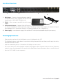
Front Panel Functions
5
7
6
3
4
2
1
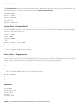
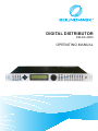
1. USB – a standard Type B USB connector. Proper device driver must be installed prior to usage. The red LED will
come on for indication when USB cable connected.
2. Mute keys – Mute/Unmute input and output channels. When an input channel is muted, a red LED will come
on for indication. When Menu Control key is pressed, it selects the corresponding channel for the LCD menu
display and is acknowledged by a green LED above the buttons. The last modified menu will be displayed on
the LCD. While the Menu Control key is held down, multiple channels can be linked or unlinked by pushing the
desired channels. This eases programming for the same parameters across multiple channels. Multiple Inputs
can be linked together and multiple outputs can be linked together. Inputs and Outputs are linked separately.
3. Peak Level LED – Indicates the current peak level of the Signal: Signal, -12dB, -6dB, -3dB, Over/Limit. The Input
Over LED references to the device’s maximum headroom. The Output Limit LED references to the threshold of
the limiter.
4. Menu keys – There are 8 menu keys for Signal-Gain/Phase/Delay, EQ, X’over (Crossover), Limiter, Channel (Input
Mix), Name (Channel name) for each input/output channel and System and Exit control for the main system.
5. Rotary Thumb Wheel – Changes parameter data values and confirm. The wheel has travel velocity sensing
which eases large incremental data modifications. For modifying delay and frequency (1 Hz resolution), pressing the Speed key simultaneously will increment/decrement the data value by 100X. To confirm the setting
push the wheel one time.
6. LCD – 4 line x 32 characters displays all the necessary information to control the unit.
7. Cursor control – 4 key for Cursor control.
page 4 | © Copyright 2012 Soundmask Australia Pty Ltd. All Rights Reserved