1
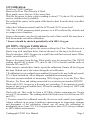
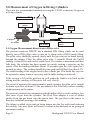
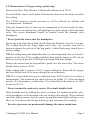
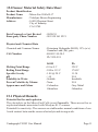
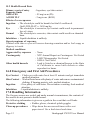
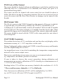
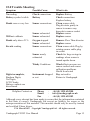
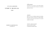
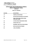
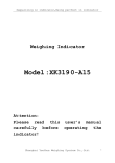
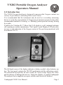
VN202 Portable Oxygen Analyser
Operators Manual
1.0 Introduction
O
The VN202 Oxygen Analyser is designed to measure the Oxygen content in a
variety of gas mixtures including Nitrox and Trimix.
It is recommended that the instrument only be used as a secondary measuring
device to verify the concentration of Oxygen in gas mixtures prepared using other
recommended methods of mixing, i.e. blending, partial pressure mixing, mixing
by weight.
It utilises the Teledyne R-17 Micro Fuel Cell which is a self contained galvanic
cell requiring no routine maintenance. The Liquid Crystal Display (LCD) provides
an easy to read indication of the Oxygen content of the gas being monitored with
a resolution of 0.1%.
The left hand corner of the display indicates a battery symbol when batteries are
low. The front panel contains the ON/OFF push button and the calibration control.
The instrument incorporates an auto switch off. Upon receipt inspect the entire
unit for damage. If damaged do not use. Notify the supplier or consult Vandagraph.
The analyser can be supplied on request with the auto-switch off disabled.
Vandagraph VN202 User Manual
Page 1
2.0 Setting Up the VN202 Oxygen Analyser
2.1 Battery Installation or replacement
A 9 volt Alkaline Battery Type MN1604, PP3 or similar must be installed in the
Vn202 to enable it to operate. Rechargeable batteries should NOT be used.
2.1.1 Slide off the compartment cover on the lower portion of the rear of the
Analyser.
2.1.2. Clip in the battery. The battery snap connector will accept a battery only
one way, do not use excessive force.
2.1.3. Take care not to damage the battery connector or wires whilst fitting the
battery and replacing the battery cover.
* Batteries must be replaced immediately the battery symbol appears in the LCD
window. Accuracy of the VN202 can not be guaranteed whilst this battery symbol
is visible.
2.2 Sensor Installation
A Teledyne R-17 Sensor must be installed before the VN202 will operate. Remove
the sensor from its protective bag and visually inspect the sensor for damage or
electrolyte leakage. Allow sensor a few minutes to stabilise after installation.
* Never use a defective or suspect sensor.
The R-17 sensor electrolyte is caustic. Do not let the electrolyte come into contact
with skin, eyes or mouth. If it does, flush the affected area with fresh water. See
section (16) on First Aid.
Do not attempt to open or repair the sensor. Check the sensor regularly for leaks.
Leaking or exhausted sensors should be disposed of in accordance with local
regulations which is usually similar to the disposal of batteries. Consult the
material safety data sheet section (15). Plug the jack on the coiled cable gently
but firmly into the sensor and tighten locking ring with fingers.
2.3 The Flow Thru Divertor
The Flow Thru divertor is designed to be used in conjunction with the Tee Piece
and only in flowing gas. Flowing gas diverted onto the sensor face improves the
response time. Failure to remove the divertor and Tee when using a bag to
measure the Oxygen content will severely lengthen the response time and can
cause substantial inaccuracies. In a stationary gas the Flow Thru divertor traps
the residual Oxygen rich gas in the area just above the sensor membrane and
severely slows down the ingress of fresh air into the sensor. A sensor left in the
air with the Flow Thru adapter in situ can take several minutes to return to 20.9%
when removed from an Oxygen enriched gas. Calibration will be inaccurate
during this period.
* Moving gas is essential when using the Flow Thru adapter.
Page 2
Vandagraph VN202 User Manual
3.0 Calibration
Switch on VN202 Analyser
Remove the Flow Thru Divertor if fitted.
Blow gently across the face of the sensor face.
Wait for the sensor to show a dip in reading to about 17% (due to CO2 in breath),
recover, and then slowly stabilize.
Do not hold the sensor in the palm of the hand as heat from the body can affect
the reading.
Adjust the Calibration control until the LCD reads 20.9% at sea level.
N.B. The VN202 measures partial pressure so will be affected by altitude and
re-compression chambers.
Sensors deteriorate very slowly and near the end of their useful life may show a
drift downwards soon after calibration.
* Sensors should be checked periodically with 100% Oxygen.
4.0 100% Oxygen Calibration
The easiest method is to place the sensor without the Flow Thru divertor in a
plastic bag with small pin holes. Ensure the neck of the bag is held closed.
Slowly introduce 100% Oxygen via a small tube and flush several times. When
stable, set calibration to 100%.
Remove the sensor from the bag. Blow gently over the sensor face. The VN202
reading should fall to about 17% (due to the CO2 in breath) and the settle at
between 20% and 22%.
If the sensor is outside these limits, repeat the calibration. Ensure all the Oxygen
has been flushed out of the sensor during the air calibration.
* If calibration is in a confined space ambient Oxygen levels may build up beyond
21%. Check in fresh air. Allow adequate ventilation in measuring area.
The most accurate method of measuring 100% Oxygen is to use the Flow Thru
Divertor, Tee Piece and tubing connected to a restrictor part number DIN22F.
Flush with 100% Oxygen at a flowrate not exceeding 5 Litre/minute (a gentle
stream of gas giving an audible hiss). When the reading is steady set 100% with
calibration control.
Flush with air. This could be from a SCUBA cylinder containing air. Do not
exceed 5 Litre/minute. The reading should fall and reach a level between 20%
and 22%.
* If sensor cannot be calibrated correctly do not use and consult your supplier.
Always calibrate in air prior to making a measurement as temperature changes
and movement of the calibration control can all cause the calibration to
accidentally move from 21%. For Oxygen mixtures above 50% always calibrate
in 100% before measurement.
Vandagraph VN202 User Manual
Page 3
5.0 Measurement of Oxygen in Diving Cylinders
There are two recommended methods of using the VN202 to measure Oxygen in
a diving cylinder.
O2 Sensor R17
Pressure restrictor
DIN22F
Flow Thru Adaptor
B-50057
Tubing
VP12
'O' Ring
Din thread
Tee A-268
Tubing to Tee Adaptor
D22M10
5.1 Oxygen Measurement direct from a Pillar valve
The pressure restrictor DIN22F has a standard DIN fitting which can be used
directly into a DIN pillar valve or into an A clamp with a DIN Female fitting.
The pillar valve should be opened slowly until the gas can just be heard hissing
through the tubing. Close the pillar valve after 5 seconds. Watch the Vn202
reading, it should rise and reach a stable level. If it reaches a maximum and then
falls back, the cylinder has been opened too much creating a pressure on the
sensor. After the reading stabilises (about 10 seconds) open the valve again for 5
seconds as above. The reading should this time peak and fall back less than 0.5%.
The stable reading is the oxygen level in the cylinder gas. If in doubt this step can
be repeated as many times as necessary until a stable reading is achieved.
If the system is left in this position air will gradually find its way back up the
tubing and the reading will begin to fall very slowly.
The secret of accurate fast measurement is gently opening the pillar valve enough
to obtain a gas flow of about 2-5 ltrs per minute (a low level hiss) without creating
a high pressure on the sensor.
The pressure restrictor in conjunction with the pillar valve is used to achieve low
flow rates of gas from the cylinder. The Flow Thru adapter is a set of blades
which divert the gas down onto the sensor face. The gas flow to the sensor is
therefore turbulent ensuring a fast reading.
The tubing is added to prevent air being drawn into the Tee outlet and reducing
the reading. Any poor joints will create a venturi action and suck in air giving an
inaccurate reading.
Page 4
Vandagraph VN202 User Manual
5.2 Measurement of Oxygen using a plastic bag
Remove the Flow Thru Divertor if fitted and Calibrate in air 20.9%.
Do not hold the sensor in the palm of the hand as heat from the body can affect
the reading.
The VN202 measures partial pressure so will be affected by altitude and
re-compression chambers.
Purge the demand valve to clear any air compressed in the hose and first stage.
Place the sensor in a plastic bag with small pin size holes along with the demand
valve. The sensor membrane should be located beside the demand valve
mouthpiece.
* Do not point the sensor into the mouthpiece.
Ensure the neck of the bag is held closed. Purge the Demand valve for 2 seconds.
The reading should rise. Purge again twice more, two seconds each and in
between squeeze the gas out of the bag gently. A third final purge should give a
steady reading.
N.B. the reading may peak higher than the real value temporarily due to excessive
pressure in the bag. If the reading stabilises then quickly begins to fall, the air
holes are too big or the neck of the bag is not being held firm enough.
Remove the sensor from the bag and blow gently over the sensor face. The sensor
should slowly return to 20.9%.
If the reading fails to return to 20.9%, repeat calibration. Ensure all the oxygen
has been flushed out of the sensor during the air calibration.
N.B. The system should always be calibrated in air 20.9% before it is used for a
measurement. The measured gas should always be within 1% of the calculated
mixture. If a discrepancy of more than 1% is found check the analyser in 100%
O2 and air 20.9%.
* Do not assume the analyser is correct. If in doubt double check
Other methods such as holding the sensor or sensor Tee against the pillar valve,
or the mouthpiece of the demand valve are strongly discouraged. These methods
can allow high pressures into the sensor giving inaccurate high readings or can
allow air to be drawn into the gas mixture giving inaccurate low readings.
* Excessive pressure can permanently damage the sensor membrane.
Vandagraph VN202 User Manual
Page 5
6.0 Repair Service
In the event the VN202 requires servicing the following steps will ensure a swift
response.
6.1 Sensor Failure
All sensors have serial numbers and have a 12 month warranty from date of
purchase. Contact your authorised distributor or Vandagraph for return instructions.
For sensors under warranty a copy of the sales invoice or proof of purchase and
the sensor serial number intact must be included on return.
6.2 Instrument Failure
There are no user replaceable parts in the instrument. The case has been sealed
and the electronics section tropicalised to retard water damage. Contact your
authorised distributor or Vandagraph for return instructions.
If the instrument is unrepairable, a replacement service exchange unit, excluding
sensor, will be offered to you on receipt of the damaged VN202 at a maximum
fixed low charge. (approximately 30% of the current list price of complete
instrument). Each replacement instrument will have a full 12 months warranty.
Warranty does not cover physical damage, damage from liquids or physical abuse.
7.0 Spare Parts And Accessories
R-17
DINKIT
Includes:
A-268
B-50057
VP12
D22M10
BS111
DIN22F
R-17 Micro Fuel Cell
DINKIT Restricter Kit
A-268 Tee Adaptor
B-50057 Flow-Thru Divertor
VP12 Tubing 30cm
D22M10 Male adapter
BS111 Viton O Ring
DIN22F Pressure Restrictor
8.0 Storage of Sensors
Never
• Store sensors for long periods before use.
• Subject sensors to high temperatures i.e. (Car rear shelf)
• Freeze sensors (left in cars overnight)
• Subject sensors to physical shocks.
• Subject sensors to vacuum
• Submerge sensors in liquids
• Attempt to open a sensor
Sensors deteriorate very slowly and near the end of their useful life may show a
drift soon after calibration. Sensors should be checked periodically in 100%
Oxygen.
Page 6
Vandagraph VN202 User Manual
9.0 Environmental effects on Oxygen measuring
9.1 Pressure
Virtually all Oxygen analysers measure the partial pressure and not the percentage
of the gas they sense. The only time these instruments can accurately read
percentages is when the pressure is atmospheric (1 Bar) and does not vary between
calibration and measurement.
It is therefore important to calibrate the VN202 at regular intervals. It is
recommended that the unit be calibrated prior to each use.
At sea level in air the partial pressure of Oxygen is approximately 0.21 and the
percentage of Oxygen will therefore read approximately 21%. If the sensor was
subjected to 2 BAR pressure in air it would read 42% (Partial pressure 0.42 Bar).
Pressures of this magnitude may be experienced by the sensor if it is placed on the
output of the pillar valve, or mouthpiece and therefore facing into the gas flow.
O2 READING
40%
20%
ALTITUDE
0 BAR
1 BAR
2 BAR
If a container or bag is used to contain the gas to be measured it must have pin
size vent holes and the pressure must be allowed to return to ambient before a
measurement is made.
Wind increases pressure and if directed on to the sensor face during calibration
can cause erratic readings.
The VN202 readings will be affected by altitude and re-compression chambers.
Altitude Km
30
25
20
15
10
5
1.0
0.8
Vandagraph VN202 User Manual
0.6
0.4
0.2
Pressure BAR
0.0
Page 7
10.0 Temperature
The Teledyne R-17 is a micro-fuel cell and a galvanic electrochemical sensor. It
is sensitive to temperature changes. A thermistor in the R-17 Oxygen sensor
adjusts for ambient changes in the range 0 - 40C (31 - 106F). Cold gas from a
cylinder directed at the face of the sensor will change the temperature and affect
the accuracy of the reading.
The temperature compensating circuit is in the base of the sensor so holding the
sensor in the palm of a hand can warm it causing inaccuracy.
OUTPUT
Thermistor Circuit
Compensated Output
Cell Output
TEMPERATURE
11.0 Humidity
For calibration purposes humidity does not directly affect the accuracy of the
sensor however:
Excessive moisture or condensation on the sensor surface will block diffusion of
Oxygen to the sensor and render it inoperative. In high humidity atmospheres
hold the sensor facing down during calibration. Any droplets will have a chance
to fall off the sensor membrane. Using the restricter method with air from a
cylinder for calibration will allow the following dry gas to evaporate any moisture
on the sensor face.
Discrepancy in readings against expected values
The VN202 is intended to be used only as a secondary means to verify the
accuracy and check the concentration of oxygen in a pre-mixed source. Whenever
a discrepancy of +/- 1% or greater is observed between the calculated mix and the
VN202 the source of the discrepancy must be resolved immediately.
* Check gas calculations
* Check method of preparation
* Check VN202 calibration both in air and 100% O2
Page 8
Vandagraph VN202 User Manual
12.0 Water & Moisture
Water in the sensor or the VN202 can render the instrument inaccurate and cause
irreparable damage. Sea water may dry leaving a deposit on connectors and sensor
membrane. Always leave the sensor jack locking ring finger tight on the sensor
socket.
The instrument has been constructed to reduce the effects of water splashed onto
it but 100% waterproofing is not guaranteed.
Signs of water in the battery compartment should be treated as a potential
instrument failure.
If the VN202 is dropped in sea water quickly remove the battery. Wipe the wet
area with fresh water and leave the VN202 battery cover off in a warm area for
several days.
Check the sensor membrane. If it is wet rinse with fresh water. Remove excess
water carefully with a paper tissue and leave to dry in a warm area. If the jack
socket on the sensor is wet the sensor is probably destroyed as the electronics
inside the sensor will also be wet. Wash out with fresh water and leave to dry out
in a warm area. If all the salt is removed corrosion may be prevented.
* Before use check sensor calibration in both air and 100% oxygen if moisture
has been a problem.
Water ingress into the VN202 can be assumed if any of the following are observed.
Dampness in the battery compartment
Micro droplets in the LCD window
Mist in the LCD window
Missing segments or digits
Battery goes flat prematurely
13.0 Specification
Range
Accuracy
Response Time
Resolution
Battery Type
Battery Life
Sensor Type
Sensor Life
Sensor output
Dimensions
Weight
Length
Storage Temp
Operating Temp
Case
: 0 - 100% Oxygen
: +/- 1% of full scale reading
: 90% in less than 10 seconds
: 0.1 %
: 9 Volt Alkaline (NOT rechargeable)
: 12 months (typical)
: R-17 (Galvanic)
: Expected 48 months in air (10 months in 100% oxygen)
: 7mV - 13mV in air (10.5mV nominal)
: 60mm x 120mm x 25mm
: 205 gm incl battery & sensor
: 250mm retracted 759mm extended
: 0-50 C (recommended 10-30C)
: 0-40 C
: Splash Proof
Vandagraph VN202 User Manual
Page 9
14.0 DO’S and DON’TS
DO
Read all of the directions before using for the first time
Calibrate before use
Keep the unit, sensor, and connections dry
Calibrate after replacing the batteries
Calibrate after replacing the sensor
Calibrate in air before every reading
Make sure the R-17 is properly attached
Visually inspect the sensor for leakage or water on the sensing surface before use
Use the plastic Flow Thru divertor when using the Tee Piece
Remove the Flow Thru divertor when measuring in a bag
Clean the case with damp cloth and mild detergent
Remove the batteries prior to extended storage
DON’T
Use the VN202 if you suspect any malfunction
Overheat or freeze the sensor
Open or try to repair a leaking or broken sensor
Immerse the sensor or instrument in any liquid
Pass hot or cold gas mixtures over the sensor face
Expose the unit to radio, short wave, microwave, X-Ray, high-frequency, or
electromagnetic radiation
Use cleaning agents or liquids in the cable receptacles or around the
battery compartment
Place the VN202 unit in a water vapour saturated environment
Expose the VN202 or sensor to excessive sunlight
Expose the VN202 or sensor to temperatures greater than 40 C (106 F)
or less than 0 C (-32 F)
Use without locking the jack plug
Use if low battery indicator shows
Page 10
Vandagraph VN202 User Manual
15.0 Sensor Material Safety Data Sheet
Product Identification
Product Name
: Micro-Fuel Cells R-17
Manufacturer
: Teledyne Brown Engineering
Address
: 16830 Chestnut Street
: City of Industry
: CA 91749
Date Prepared or Last Revised
Emergency Phone Number
Physical and Chemical Data
Chemical and Common Names
CAS Number
Melting Point/Range
Boiling Point/Range
Specific Gravity
pH
Solubility in Water
Percent Volatiles by Volume
Appearance and Odour
: 08/08/91
: 001 818 961 9221
: Potassium Hydroxide (KOH), 15% (w/v)
: Granular Lead (Pb), pure
: KOH 1310-58-3
: Pb 7439-92-1
: KOH
: 10 to 0 C
: 100 to 115 C
: 1.09 @ 20 C
: >14
: Soluble
: None
: Colourless
: Odourless
Pb
328 C
1744 C
11.34
N/A
Insoluble
N/A
Grey Metal
Odourless
15.1 Physical Hazards
Potential for fire and explosion
The electrolyte in the Micro-Fuel Cells is not flammable. There are no fire or
explosion hazards associated with Teledyne R-17 sensors.
Potential for reactivity: The sensors are stable under normal conditions of use.
Avoid contact between the sensor electrolyte and strong acids.
Vandagraph VN202 User Manual
Page 11
15.2 Health Hazard Data
Primary route of entry
: Ingestion, eye/skin contact
Exposure limits
OSHA PEL
: .05 mg/cu.m (Pb)
ACGIH TLV
: 2 mg/cu.m. (KOH)
Effects of over-exposure
Ingestion : The electrolyte could be harmful or fatal if swallowed.
Oral LD50 (RAT) = 3650 mg/kg
: The electrolyte is corrosive; eye contact could result in permanent
Eye
loss of vision.
: The electrolyte is corrosive; skin contact could result in a chemical
Dermal
burn.
Inhalation : Liquid inhalation is unlikely.
Signs/symptoms of exposure
Contact with skin or eyes will cause a burning sensation and/or feel soapy or
slippery to touch.
Medical conditions
: None
Aggravated by exposure
: NTP Annual Report on Carcinogens: Not Listed
Carcinogenity
: LARC Monographs: Not Listed
: OSHA: Not Listed
Other health hazards
: Lead is listed as a chemical known to the State
of California to cause birth defects or other
reproductive harm.
16.0 Emergency and First Aid Procedures
Eye Contact : Flush eyes with water for at least 15 minutes and get immediate
medical attention.
Skin Contact : Wash affected area with plenty of water and remove contaminated
clothing. If burning persists, seek medical attention.
Ingestion
: Give plenty of cold water. Do not induce vomiting. Seek medical
attention.
Inhalation : Liquid inhalation is unlikely.
17.0 Handling Information
The Oxygen sensors are sealed, and under normal circumstances, the contents of
the sensors do not present a health hazard.
The following information is given as a guide in the event that a cell leaks.
: Rubber gloves, chemical splash goggles
Protective clothing
Clean-up procedures : Wipe down the area several times with a wet
paper towel. Use a fresh towel each time.
Page 12
Vandagraph VN202 User Manual
17.1 Protective Measures
During sensor replacement: before opening the bag containing the sensor, check
the sensor for leakage. If the sensor leaks, do not open the bag.
If there is liquid around the sensor e.g. whilst in the instrument case, put on
gloves and eye protection before removing the sensor.
17.2 Disposal
Should be in accordance with all applicable state, local and federal regulations.
NOTE: The above information is derived from the MSDS provided. The
information is believed to be correct but does not purport to be all inclusive and
shall be used only as a guide. Neither Teledyne Brown Engineering nor
Vandagraph Ltd shall be held liable for any damage resulting from handling or
from contact with the above product.
18.0 General Care of the VN202
The VN202 is a very accurate instrument and if looked after will give many years
of accurate Oxygen measurement.
There are very few parts to wear out and the instrument is robust and designed to
be used in the diving environment.
The instrument should be cleaned with warm soapy water (Not immersed).
No detergents or solvents should be used on the sensor.
Never use the VN202 once the low battery indicator is visible. From this point
the electronics quickly become unstable and will give false readings.
Do not subject the VN202 to mechanical shocks. Although robust the LCD
display is a glass component and can be broken. This is usually apparent by black
areas spreading across the LCD screen.
The VN202 should be kept in a container when not in use and should be shielded
from high and low temperatures. Do not leave on the dashboard or rear window
shelf of a car.
Protect the LCD from long periods of sunlight.
Good quality batteries should last at least one year (NOT rechargeable).
Alkaline batteries are recommended because of their expected life, discharge
curves and overall reliability and stability.
Take care when changing the batteries not to break the battery wires or distort the
connections.
Try not to trap wires in the battery cover.
Vandagraph VN202 User Manual
Page 13
19.0 Care of the Sensor
The sensor should be checked with an air calibration a week before each dive trip
(allowing time for a replacement to be obtained) and always just prior to a
measurement being taken.
The sensor can also be cleaned with warm water but care should be taken to
follow the advice on page 9 concerning moisture. Do not use excessive force to
screw the sensor into the Flow-Thru divertor as damage can be caused to the
threads.
20.0 Sensor Life
The life of a sensor in the VN202 depends on the amount of Oxygen to which it
is exposed and is not affected by whether the VN202 is switched on or off.
A Teledyne R-17 will theoretically work for 48 months if left in air and 10 months
if left in 100% 02. The sensor warranty is 12 months from the invoice date. These
expected life figures can be drastically shortened if the sensor is physically abused.
The sensor should be stored with the VN202 in the same protective case when it
is not being used.
21.0 VN202 Accuracy
The readout device has a 0.1% resolution and can therefore only display with a
maximum accuracy of +/- 0.1% anywhere on the scale.
During Vandagraph quality control each VN202 is tested for accuracy and linearity
over the complete range 0% to 100%.
An insignificant error is involved in matching the temperature compensation
network to the sensor output curve.
Most errors contributing to inaccuracy are user or environment induced.
e.g. temperature, movement, pressure or moisture.
If care is taken to observe the correct procedures during calibration and
measurement an accurate calibration at 20.9% should give a maximum error of
+/- 0.5% in 100% Oxygen.
Readings below 21% will have an accuracy limited to the resolution of +/-0.1%
* The overall accuracy claimed is +/- 1% of full scale.
Note, that errors in calibration at 20.9% will be multiplied by 5 at 100%.
e.g. set 20% in air will cause 100% Oxygen to read 95%.
Page 14
Vandagraph VN202 User Manual
22.0 Trouble Shooting
Symptom
Possible Cause
What to do
No reading
Battery symbol visible
Check connections
Battery
Reads zero or very low
Sensor connections
Will not calibrate
Sensor exhausted
Sensor exhausted
Replace Battery
Check connections
Replace battery
Clean sensor cable
Plug & rotate gently in
sensor to remove any
deposits in sensor socket
Replace sensor
Replace sensor
Reads only above 21%
Erratic reading
Oxygen trapped
Sensor exhausted
Sensor connections
Sensor nearly
exhausted
Windy Conditions
Digits incomplete,
Random Digits,
No Digits,
LCD Cloudy,
Battery contacts are
discoloured
Instrument dropped
or wet
Remove Flow Thru-divertor
Replace sensor
Clean sensor cable Plug by
rotating sensor cable plug
in socket
Check for large swings in
readings when sensor is
turned upside down
Wind affects pressure on
sensor surface and causes
calibration problems.
Shield from wind
Dry out and/or
Return to Vandagraph
Helpline Contact on
Phone
:
+44 (0) 1535 634900
Email
:
[email protected]
Fax
:
+44 (0) 1535 635582
Although every attempt has been made to ensure that the information contained
in this data is correct, Vandagraph Ltd accept no liability for errors or the
misrepresentation of this material. This monitor should only be used by trained
and certified Nitrox divers.
V2.4 March 2007. Copyright Vandagraph Ltd. All rights reserved.
Vandagraph VN202 User Manual
Page 15
Table of Contents
Chapter
1
2
2.1
2.2
2.3
3
4
5
5.1
5.2
6
6.1
6.2
7
8
9
9.1
10
11
12
13
14
15
15.1
15.2
16
17
17.1
17.2
18
19
20
21
22
Contents
Introduction
Setting up the VN202 Oxygen Analyser
Battery installation or replacement
Sensor installation
Flow Thru Divertor
Calibration
100% Oxygen calibration
Measurement of oxygen in diving cylinders
Measurement of oxygen using a pillar valve
Measurement of oxygen using a plastic bag
Repair service
Sensor failure
Instrument failure
Spare parts and accessories
Storage of sensors
Environmental effects on Oxygen measuring
Pressure
Temperature
Humidity
Water & moisture
Specification
Do’s and Don’ts
Material safety data sheet
Physical hazards
Health hazard data
Emergency and first aid procedures
Handling Information
Protective measures
Disposal
General care of the VN202
Care of the sensor
Sensor life
Accuracy of the VN202
Trouble shooting
Page
1
2
2
2
2
3
3
4
4
5
6
6
6
6
6
7
7
8
8
9
9
10
11
11
12
12
12
13
13
13
14
14
14
15
VANDAGRAPH Ltd
15 Station Road, Cross Hills, Keighley, West Yorkshire, England, BD20 7DT, UK
Tel: +44 (0) 1535 634900 Fax: +44 (0) 1535 635582
www.vandagraph.co.uk
Page 16
Vandagraph VN202 User Manual