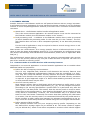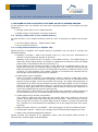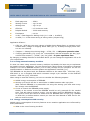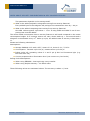
1
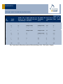
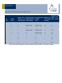
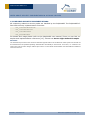
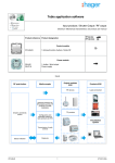
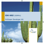
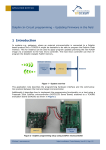
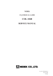
APPLICATION NOTE 511 Advanced security in self-powered wireless applications NOTES ABOUT SECURITY IN SELF-POWERED DEVICES © EnOcean | www.enocean.com Author (eo_fusszeile) | September 2013 | Page 1/ 13 APPLICATION NOTE 511 NOTES ABOUT SECURITY IMPLEMENTAION IN SELF-POWERED DEVICES Table of contents ONS | CHRISTAPPLICATION NOTE 308 1. INTRODUCTION .............................................................................................................................................. 3 1.1. 1.2. 1.3. 2. AUTARKIC DEVICES ..................................................................................................................................... 5 2.1. 3. DEFINITIONS ................................................................................................................................................ 3 REFERENCES................................................................................................................................................ 3 REVISION HISTORY...................................................................................................................................... 4 COMMON TASKS OF AUTARKIC DEVICES WITH SECURITY FEATURES............................................................ 5 IMPLEMENTATION OF SECURITY FEATURES ON SELF-POWERED DEVICES ........................... 7 3.1. STORING ROLLING CODE IN NON-VOLATILE MEMORY .................................................................................. 7 3.1.1. Using internal memory of Dolphin Chip ................................................................................................ 7 3.1.2. Using external memory modules ............................................................................................................ 8 3.2. ENERGY CONSUMPTION WITH SECURITY...................................................................................................... 8 4. AVAILABLE SECURITY IMPLEMENTATIONS ..................................................................................... 13 © EnOcean | www.enocean.com Marian Hönsch | September 2013 | Page 2/ 13 APPLICATION NOTE 511 NOTES ABOUT SECURITY IMPLEMENTAION IN SELF-POWERED DEVICES 1. INTRODUCTION ONS | CHRISTAPPLICATION NOTE 308 This document describes how to include security into autarkic applications. This applies primary to sensor applications. Before reading this document you should be familiar with the “Security EnOcean for Radio Networks” specification [1.]. You can also find a good summary in the App Note 509 [14.]. In this application note we will focus on adding security to the customer programmable EnOcean Modules. This includes: STM 3XY (C/U) with Dolphin API STM 4XY J with Dolphin V4 API 1.1. Definitions Term / Abbr. µC AES API APP ASK CBC CMAC CRC DATA Device EEP EHW ERP ESP3 FSK Gateway GP ID KEY MAC MSB PSK PTM RLC R-ORG SLF TXID VAES Description Microcontroller (external) Advanced Encryption Standard Application Programming Interface Application Amplitude Shift Keying Cipher Block Chaining Cipher Based Message Authentication Code Cyclic Redundancy Codes Payload of a radio telegram Customer end-device with an integrated EnOcean radio module EnOcean Equipment Profile Energy Harvested Wireless protocol EnOcean Radio Protocol (ERP1 = Version 1, ERP2 = Version 2) EnOcean Serial Protocol V3 Frequency Shift Keying Module with a bidirectional serial communication connected to a HOST Generic Profiles Unique module identification number Specific parameter used to encrypt / decrypt / transform DATA Message Authentication Code Most Significant Byte Pre-shared Key Pushbutton Transmitter Module Rolling Code Message parameter identifying the message type Security Level Format specifying which security parameters are used ID of a transmitter Variable AES 1.2. References [1.] Security of EnOcean radio networks (System Specification) http://www.enocean.com/en/security-specification/ [2.] http://www.kotfu.net/2011/08/what-does-it-take-to-hack-aes/ [3.] EEP Specification - http://www.enocean-alliance.org/eep/ © EnOcean | www.enocean.com Marian Hönsch | September 2013 | Page 3/ 13 APPLICATION NOTE 511 NOTES ABOUT SECURITY IMPLEMENTAION IN SELF-POWERED DEVICES [4.] Specification - http://www.enocean-alliance.org/ ONS | GP CHRISTAPPLICATION NOTE [5.] 308 EnOcean Radio Protocol 1 - http://www.enocean.com/fileadmin/redaktion/pdf/tec_docs/EnOceanRadioProtocol.pdf [6.] Smart Acknowledge http://www.enocean.com/fileadmin/redaktion/pdf/tec_docs/SmartAcknowledgement.pdf [7.] Remote Management http://www.enocean.com/fileadmin/redaktion/pdf/tec_docs/RemoteManagement.pdf [8.] Gateway Controller http://www.enocean.com/en/enocean-software/gateway-controller/ [9.] Dolphin V4 Gateway Controller http://www.enocean.com/en/enocean-software/ [10.] EnOcean Link http://www.enocean.com/en/enocean-software/enocean-link/ [11.] EnOcean Link Gateway example: http://www.enocean.com/fileadmin/redaktion/support/enoceanlink/_gateway_example_8cpp-example.html [12.] Decoding Gateway http://www.enocean.com/en/enocean-software/decoding-gateway-controller/ [13.] DolphinAPI http://www.enocean.com/en/download/ [14.] Application Notes http://www.enocean.com/en/application-notes/ 1.3. Revision History No 1.0. Major Changes First version © EnOcean | www.enocean.com Marian Hönsch | September 2013 | Page 4/ 13 APPLICATION NOTE 511 NOTES ABOUT SECURITY IMPLEMENTAION IN SELF-POWERED DEVICES 2. AUTARKIC DEVICES ONS | CHRISTAPPLICATION NOTE 308devices in the EnOcean world are self-powered devices with an energy harvester. Autarkic A self-powered sensor application for most practiced purposes consists of only an EnOcean module. In more complex applications external µC are also used. Therefore we define these use cases: Stand alone - the EnOcean module handles all application tasks. This is the most common application. An external sensor circuit can be connected to the EnOcean module, but the EnOcean module is the “master”. Dual processing units – in addition to the EnOcean module there is also an external µC which handles the processing tasks. In this case the µC is the “master”. The Dolphin Module does not have to be a transparent gateway. It can also take processing tasks. For this kind of application it may be required to have a second energy source in addition to energy harvesting. Most sensors are unidirectional. If an energy autarkic device is bidirectional then in most cases it uses the Smart Acknowledge protocol [6.]. For information on performing security with Smart Acknowledge and bidirectional communication please refer to Application Note 509 [14.]. The unidirectional sensors have to protect only the outgoing communication with security features. For the security features only one pair of KEY and RLC is required. We refer to a pair of RLC and KEY as security profile. 2.1. Common tasks of autarkic devices with security features Compared to non-secured application a secured autarkic application has to consider these additional tasks and constrains: Define the SLF of outgoing communication. This is a very important task, because it will determine the security features used and also what additional implementation features must be considered (e.g. RLC). They may be a trade-off between security features and device capabilities. Please consider here therefore the nature of your application and what security protection is required. A good approach might is to define what attacking scenarios can occur or what potential harm may be done. Send out security teach-in. Most autarkic sensors have a LRN button which will transmit a profile teach-in telegram. Please refer to the profile specification [3.], [4.] for the telegram structures. According to the security specification a profile teach-in is performed only after the “security link” has been build. This means, that the security teach-in must be transmitted prior to the profile teach-in. Here another LRN button can be used for the security teach-in functionality. However, the recommended way is to perform both teach-ins with one button. Practically this means that after pressing the LRN button on a sensor, first the security teach in is transmitted followed by the profile teach-in. Please consider to add a sleep time between the telegram transmissions so the energy circuit can reload and provide the needed charge for the telegram transmission. Define storage of RLC and KEY. Most common sensors have only one outgoing security profile. Depending on the SLF defined RLC storage might not be needed at all. The sensor needs to support only its defined SLF, which is less effort compared to receivers which should support © EnOcean | www.enocean.com Marian Hönsch | September 2013 | Page 5/ 13 APPLICATION NOTE 511 NOTES ABOUT SECURITY IMPLEMENTAION IN SELF-POWERED DEVICES possible SLFs. Storing the RLC will be a key feature which will be discussed in the ONS | all CHRISTAPPLICATION following chapters. NOTE 308 Please consider here that an autarkic application can also run out of energy. Therefore RLC must be stored in non-volatile memory. This is a new constraint for most autarkic application which did not previously have any non-volatile storage for application data. Protect outgoing communication with defined security features. Using security features adds additional tasks in computing time and also additional payload in telegrams. These two facts will affect the energy budget for data communication. But the added effort is still minor in comparison to the entire energy consumption. In this document we will described this calculation in detail. Resynchronisation of RLC. After losing synchronisation of RLC with one of the receivers, the sensor needs to retransmit its current RLC state. In case of a sensor this can mean retransmitting the security teach-in telegram. It is important to consider this fact during design of the LRN button position. Non-secure application required the LRN button only for profile teach-in which was mostly one-in-the-lifetime operation of the application. In this case we must consider that desynchronisation of the RLC can occur. The LRN button or other “resynchronisation possibility” should be provided to end-user without complex tasks or third party involvement. In next chapter we describe the possibilities on how to implement these tasks on the Dolphin platform with the DolphinAPI. © EnOcean | www.enocean.com Marian Hönsch | September 2013 | Page 6/ 13 APPLICATION NOTE 511 NOTES ABOUT SECURITY IMPLEMENTAION IN SELF-POWERED DEVICES 3. IMPLEMENTATION OF SECURITY FEATURES ON SELF-POWERED DEVICES ONS | CHRISTAPPLICATION NOTE In the308 following text we describe the two most important aspects of an autarkic security application: Storage of the RLC in non-volatile memory Added energy consumption of security features 3.1. Storing rolling code in non-volatile memory To store the RLC a non-volatile memory must be used. In general two options are available: Use the Dolphin Memory – RAM0 and/or Flash Use an external memory. 3.1.1. Using internal memory of Dolphin Chip Storing the RLC in Dolphin non-volatile memory is possible, but you have to consider the following aspects: Strategy of storage – what is the storing cycle (e.g. only every 30th transmission is stored) or what triggers a storage of the RLC? Between write cycles the RLC is stored in the RAM0 memory. The RAM0 keeps its state also during Deep Sleep. For details on RAM0 and functions to write the RAM0 please refer to the Dolphin API user manual [13.]. If the autarkic device powers-up after it went off due to insufficient energy the restored RLC from the non-volatile memory might be “old”. Using this RLC in security features would cause the receiver not being able to process it, because its RLC count is higher. If using storage cycle please consider to increment the restored RLC by the storage period itself to prevent this situation. If flash page erase is possible. Here it is crucial to evaluate if an application is able to perform a flash page erase. The consumption of such operation is typically 20 mA for 20 ms. It must be secured that the energy supply circuit can provide this energy. If a page erase operation is interrupted by a brown-out the actual and also other flash pages can be corrupted, which can result into application failure. In general we would not recommend performing a flash page erase on an autarkic device without taking extra measures to ensure the needed energy for the erase process. Write operation is also critical, but the flash page write operation takes typically 20 µs and consumes 20 mA. For details please see the Dolphin (V4) core description. A flash page can be written sequentially. This means a 256 byte long page can be written 256 times, before it has to be erased. An already written byte cell cannot be overwritten – this will result in failure. Once a byte cell is written, the whole page must be erased to rewrite this particular cell. Therefore we recommend first completely fill up the page and then do a possible erase. What free flash memory is available – how many pages (a 256 b) of flash are free? Transmission period – what is the average count of transmitted telegram per day? What is the expected application lifetime? Please consider this example of an application which uses the Dolphin flash memory to store the RLC without page erase possibility. © EnOcean | www.enocean.com Marian Hönsch | September 2013 | Page 7/ 13 APPLICATION NOTE 511 NOTES ABOUT SECURITY IMPLEMENTAION IN SELF-POWERED DEVICES page size – 256 b ONS | Flash CHRISTAPPLICATION NOTE 308 Writing current – typ. 20 mA Writing time – typ. 20 µs STM 300 ~ 13 kb Source code Dolphin Module - 32 kb total memory Free Space ~ 19 kb 19 kb – Flash Pages for Rolling Code (19 * 1024 = 19 456 b) 19 456 / 2 = 9 728 times saving of rolling codes (2 bytes long) Application lifetime: STM 3xy / STM 4xy can store values in RAM0 during Deep Sleep, so storage is only needed when voltage is dropping below VON (2,5 V). If always enough power Sensor can run infinitely. if approx. 1 Voltage drop during Week – 9 728 / 52 = 187 years operation time if storing periodically (e.g. every 30th transmission) with 96 telegrams per day (typical STM 330 scenario) – (9728 / (96 / 30))/365 = 8 years operation time By changing or adding features as described above you can change the application life to fit your requirement. 3.1.2. Using external memory modules In most use cases using external memory modules is probably the best way to implement an autarkic security application. You can choose from a large variety of modules. A practical example is to use an EEPROM module (1 kb or less) through the I2C interface. For the I2C implementation on EnOcean modules please see Application note 508 [14.]. The EEPROM can be placed with the EnOcean Module on the same PCB – STM 300 (C/U), STM 400J or on a daughter PCB which connects trough a pin interface to the EnOcean module – STM 330 (C/U), STM 430J. When using an external memory you have to consider the following aspects: Added energy consumption of EEPROM. Storing cycle and if the RLC is stored also in RAM0 between wake up cycles. With external EEPROM it is practicable not using the storing cycle and write every RLC change into the EEPROM. Circuit to control the EEPROM power supply. Similar to the sensor circuit the EEPROM should be only powered for the needed time. This will help to conserve energy. You can either hook the EEPROM to the Sensor control circuit and control a sensor and the EEPROM with one pin (e.g. SWPWR on STM 330) or define another control pin. See the User Manual of STM 300 for details on control circuits. 3.2. Energy consumption with security Added energy consumption of security features on an autarkic application are influenced by these parameters: What is the cost of storing the RLC? © EnOcean | www.enocean.com Marian Hönsch | September 2013 | Page 8/ 13 APPLICATION NOTE 511 NOTES ABOUT SECURITY IMPLEMENTAION IN SELF-POWERED DEVICES parameter depends on the storage itself. ONS | This CHRISTAPPLICATION NOTE308 What is the added payload in telegrams coming from security features? Every added byte to the telegram will prologue the transmission time by ~ 90 µs. What is the added computing time coming from security features? One AES 128 encryption cycle takes ~ 1 ms. If using VAES and CMAC 2 ms of computing time must be added. The whole added consumption due to security features is still small compared to the entire consumption budget. In a common sensor use case, where wake up = 100 seconds and a telegram is transmitted every 10th wake up cycle, the added costs of security is less than 1 %. Please see following calculations: Assumptions: Storage PAS614L-VL3 with 0.25 F, Umax=3.2 V, Umin=2.2 V, T=25°C Consumption: Transmit cycle 100 μC, measurement cycle 30 μC Indoor solar cell, operating values 3 V and 5 μA @ 200 lux fluorescent light (e.g. ECS 300 solar cell) Current proportional to illumination level (not true at very low levels!) Rolling Code Assumptions: When using EEPROM – Storing during every transfer When using Dolphin Memory – No Flash erase These following values are estimated values. The accuracy is about +/-20%. © EnOcean | www.enocean.com Marian Hönsch | September 2013 | Page 9/ 13 APPLICATION NOTE 511 NOTES ABOUT SECUIRTY IMPLEMENTAION IN AUTARKIC DEVICES Wake Transmit Operation Time in darkness [h] when storage fully charged Required reload time [h] at 200 lux within 24 h for continuous operation 24h operation after 6h illumination at x lux Illumina-tion level in lux for continuous operation Current in μA required for con-tinuous operation cycle[s] interval ONS | CHRISTAPPLICATION 1NOTE 308 1 0,5 Storage too small Storage too small 5791 130 1 10 1,7 Storage too small Storage too small 1791 40 1 100 2,2 Storage too small Storage too small 1391 31 10 1 5 Storage too small Storage too small 591 13 10 10 16 23 Storage too small 191 4,3 10 100 20 18 Storage too small 151 3,4 100 1 43 9 284 71 1,6 100 10 99 4 124 31 0,7 100 100 114 3 108 27 0,6 Table 1 Typical values for EnOcean Sensor module using no additional security features. APPLICATION NOTE 511 NOTES ABOUT SECUIRTY IMPLEMENTAION IN AUTARKIC DEVICES Wake cycle[s] Transmit interval ONS | CHRISTAPPLICATION Operation Time in darkness [h] when storage fully charged Required reload time [h] at 200 lux within 24 h for continuous operation 24h operation 6h illumination at x lux after Illumina-tion level in lux for continuous operation Current quired tinuous 1NOTE 308 1 0,4 Storage too small Storage too small 7791 175 1 10 1,6 Storage too small Storage too small 1991 45 1 100 2,2 Storage too small Storage too small 1411 32 10 1 4 Storage too small Storage too small 791 17,80 10 10 15 25 Storage too small 211 4,75 10 100 20 18 Storage too small 153 3,45 100 1 34 11 364 91 2,05 100 10 93 4 132 33 0,75 100 100 113 3 109 27 0,61 Table 2 Typical values for EnOcean Sensor module with Rolling Code Storage in Flash – CMAC transfer in Telegrams. in μA refor conoperation APPLICATION NOTE 511 NOTES ABOUT SECUIRTY IMPLEMENTAION IN AUTARKIC DEVICES Wake cycle[s] Transmit interval ONS | CHRISTAPPLICATION Operation Time in darkness [h] when storage fully charged Required reload time [h] at 200 lux within 24 h for continuous operation 24h operation after 6h illumination at x lux Illumina-tion level in lux for continuous operation Current quired tinuous 1NOTE 308 1 0,4 Storage too small Storage too small 8013 180 1 10 1,5 Storage too small Storage too small 2013 45 1 100 2,2 Storage too small Storage too small 1413 32 10 1 4 Storage too small Storage too small 813 18,30 10 10 14 26 Storage too small 213 4,80 10 100 20 18 Storage too small 153 3,45 100 1 33 11 373 93 2,10 100 10 93 4 133 33 0,75 100 100 113 3 109 27 0,62 Table 3 Typical values for EnOcean Sensor module with Rolling Code Storage in EEPROM – CMAC transfer in Telegrams in μA refor conoperation APPLICATION NOTE 511 NOTES ABOUT SECUIRTY IMPLEMENTAION IN AUTARKIC DEVICES 4. AVAILABLE SECURITY IMPLEMENTATIONS ONS | CHRISTAPPLICATION NOTE 308 All computing related to security tasks are handled by the DolphinAPI. The DolphinAPI offers these security implementation functions: sec_convertToNonsecure sec_convertToSecure sec_createTeachIn sec_parseTeachIn For details and usage please refer to the DolphinAPI user manual. There you can find examples and implementation references [13.]. Please see Secure Light Control Example. Disclaimer The information provided in this document describes typical features of the EnOcean radio system and should not be misunderstood as specified operating characteristics. No liability is assumed for errors and / or omissions. We reserve the right to make changes without prior notice. For the latest documentation visit the EnOcean website at www.enocean.com. © EnOcean | www.enocean.com Marian Hönsch | September 2013 | Page 13/ 13