1
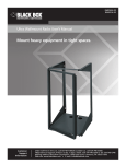
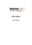
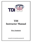
RM610A-R2
Server Side-Mount Wall Cabinet User’s Manual
Save space when mounting servers in long
BLACK BOX
or narrow rooms.
®
RM610A-R2
Customer
Support
Information
Order toll-free in the U.S.: Call 877-877-BBOX (outside U.S. call 724-746-5500)
FREE technical support 24 hours a day, 7 days a week: Call 724-746-5500 or fax 724-746-0746
Mailing address: Black Box Corporation, 1000 Park Drive, Lawrence, PA 15055-1018
Web site: www.blackbox.com • E-mail: [email protected]
Trademarks Used in this Manual
Trademarks Used in this Manual
Black Box and the Double Diamond logo are registered trademarks of BB Technologies, Inc.
Any other trademarks mentioned in this manual are acknowledged to be the property of the trademark owners.
We‘re here to help! If you have any questions about your application
or our products, contact Black Box Tech Support at 724-746-5500
or go to blackbox.com and click on “Talk to Black Box.”
You’ll be live with one of our technical experts in less than 30 seconds.
Page 2
724-746-5500 | blackbox.com
RM610A-R2
Table of Contents
Preface.................................................................................................................................................................................................... 4
Safety
.................................................................................................................................................................................... 4
Safety Symbols Used in this Manual........................................................................................................................................... 4
Safety Considerations................................................................................................................................................................ 4
1. Specifications .................................................................................................................................................................................... 5
2. Overview
.................................................................................................................................................................................... 8
2.1 Introduction.............................................................................................................................................................................. 8
2.2 Features.................................................................................................................................................................................... 8
2.3 What’s Included........................................................................................................................................................................ 8
2.4 Optional Accessories................................................................................................................................................................. 8
3. Mounting Instructions........................................................................................................................................................................ 9
3.1 Receiving, Unpacking, and Removing the Server Side-Mount Wall Cabinet from the Box.......................................................... 9
3.2 Wood Studded Wall.................................................................................................................................................................. 9
3.3 Masonry Wall Surface............................................................................................................................................................... 9
3.4 Loading Equipment..................................................................................................................................................................10
3.5 Power ...................................................................................................................................................................................10
3.6 Protective Grounding...............................................................................................................................................................10
3.6.1 Connecting the Main Protective Grouding Stud to the Dedicated Branch Ground.......................................................10
3.6.2 Connecting the Main Protective Grounding Stud to the Protective Bonding Conductors..............................................10
4. Operation
...................................................................................................................................................................................11
4.1 Operating the Door..................................................................................................................................................................11
4.2 Removing or Installing a Door..................................................................................................................................................11
4.3 Removing the Front Panel........................................................................................................................................................11
5.
Optional Accessories Drawings..........................................................................................................................................................12
RM610A-R2
Page 3
Preface/Safety Information
Preface
This manual is provided to prevent service personnel from committing an act that results in the risk of fire, electric shock, or injury
to persons. Only trained service personnel should receive, unpack, and assemble the Server Side-Mount Wall Cabinet. In addition,
only trained service personnel should install equipment in enclosures.
Safety
Safety Symbols Used in this Manual
This manual provides general safety guidelines to be observed during installation, operation, and maintenance of the Server SideMount Wall Cabinet.
WARNING: Failure to follow directions in the warning could result in injury to persons or loss of life.
CAUTION: Failure to follow directions in the caution could result in damage to equipment or storage data.
Safety Considerations
WARNING: Improper handling and use of the RM610A-R2 could result in equipment damage, serious injury,
or possible death.
Only trained service personnel should be used to remove the enclosure from the pallet. Also be sure you have a sufficient number
of service personnel. Do not attempt to move enclosures by yourself.
Only UL® Listed ITE units should be installed inside the RM610A-R2.
Be sure to read and follow all individual manufacturer equipment manuals for safety and installation instructions.
The RM610A-R2 was not evaluated as a fire enclosure.
Proper spacing is required when installing electrical equipment to avoid electrical shock.
The ambient temperature operating range for the RM610A-R2 and accessories is +50 to +95° F (+10 to +35° C).
The non-operating temperature is -4 to +140° F (-20 to +60° C).
Page 4
724-746-5500 | blackbox.com
RM610A-R2
Chapter 1: Specifications
1. Specifications
Construction —
Body: 14-gauge steel;
Doors: 16-gauge steel;
Rails: 12-gauge steel
Door Height — 24" (60.1 cm)
Door Width — 18.5" (46.7 cm)
Finish — Black powder coat
Maximum Rail Depth — 29.75" (75.6 cm)
Mounting Holes — Designed for 1⁄4" hardware
Number of Rack Units (RUs) — 10
Rail Type — M5
Size — 24"H x 36.1"W x 20.5"D (60.1 x 91.7 x 52.1 cm)
Weight Capacity — 250 lb. (113.6 kg)
36.1" (96.1 cm)
Figure 1-1. Front view.
EC24U3032
724-746-5500 | blackbox.com
Page 5
Chapter 1: Specifications
Figure 1-2. Right side view.
20.5" (52.1 cm)
19.5" (49.5 cm)
34" (86.4 cm)
36.1" (91.6 cm)
Figure 1-3. Top view.
Page 6
724-746-5500 | blackbox.com
RM610A-R2
Chapter 1: Specifications
14" (35.6 cm)
16.0" (40.6 cm)
16.0" (40.6 cm)
16.0" (40.6 cm)
Figure 1-4. Back view.
RM610A-R2
Page 7
Chapter 2: Overview
2. Overview
2.1 Introduction
The Server Side-Mount Wall Cabinet is designed for servers and other networking equipment.
2.2 Features
• Ships with one conduit panel on the bottom and one gland plate on the top.
• 3 RU cabinet accessories also fit the RU openings, top and bottom.
• Welded steel frame.
• Includes two pairs of M5 rails.
• Front door is mesh.
• Rear door has mounting positions for fans.
• Side panel and doors are removable for equipment access.
• Locking doors and side panels.
2.3 What’s Included
Your package should include the following items. If anything is missing or damaged, please contact Black Box Technical Support
at 724-746-5500 or [email protected].
• (1) Server Side-Mount Cabinet
• (2) sets of keys
• (1) gland plate
• (1) conduit panel
• (20) M5 screws and cage nuts
• (16) M5 flat-head screws and nuts
• (4) fan guards
• This user manual
2.4 Optional Accessories
• Fan Tray (RM4002A)
• Filter Tray (RM4003A)
• Blanking Panel (RM4004A)
• Fan for rear door (RMT373-R2)
• 3 RU Conduit Adapter Plate (ECP3U)
• 3 RU Brush Grommet Kit (ECBGK3U)
• 3 RU Waterfall Radius Bracket (ECW3U)
• 3 RU Gland Plate Kit (EC3UGP)
• 3 RU Filler Panel (RMTB03)
Page 8
724-746-5500 | blackbox.com
RM610A-R2
Chapter 3: Mounting Instructions
3. Mounting Instructions
3.1 Receiving, Unpacking, and Removing the Server Side-Mount Cabinet from the Box
Inspect for damage and report damage if there is damage before receiving. Refer to Section 2.3 for what‘s included
in the package.
Unpack the enclosure by carefully removing the corrugated carton and corners. Avoid damaging the enclosure when removing
packaging.
WARNING: Only trained service personnel should remove the enclosure from the pallet. Also be sure you have a
sufficient number of service personnel. Do not attempt to move enclosures by yourself.
WARNING: Be careful when moving enclosures before installation. Sudden stops and starts, excessive force, obstructed routes,
and uneven floor surfaces may cause the enclosure to topple over.
3.2 Wood Studded Wall
Once the location on the wall has been determined, inspect the wall surface. The wall must be flat and square in the horizontal
and vertical plane to ensure the Server Side-Mount Wall Cabinet closes correctly. If the wall is not flat and square, you might need
to use shims.
You can remove the rear section of the cabinet by removing the hinges. Mount the rear section to the wall using the
included hardware or install two horizontal bolts in studs (DO NOT TIGHTEN!) using a level. Hang the rear section on the two
bolts, install the lower two bolts (line up with a level) and tighten. Then tighten the upper two bolts.
WARNING: Improper handling and use of the Server Side-Mount Wall Cabinet could result in equipment damage, serious injury,
or possible death.
3.3 Masonry Wall Surface
RM610A-R2
Page 9
Chapter 3: Mounting Instructions
For a masonry wall surface, the installer must provide the appropriate hardware.
3.4 Loading Equipment
WARNING: Only install equipment after the Server Side-Mount Wall Cabinet has been properly secured and mounted to the wall.
Maximum Load Capacity = 250 lb. (113.6 kg)
3.5 Power
When using power distribution units (PDUs), each PDU should be connected to a committed branch circuit that is rated for the
continuous load of all the equipment connected.
When not using a PDU, each piece of equipment should be connected to a dedicated branch circuit.
3.6 Protective Grounding
A main protective earthing stud and grounding studs are provided.
WARNING: To avoid injury to persons or loss of life, ground each enclosure individually to the dedicated branch circuit earthing
ground.
3.6.1 Connecting Main Protective Grouding Stud to the Dedicated Branch Circuit Earthing Ground
Conductor
Connect the dedicated branch circuit ground conductor to the main protective earthing stud located inside at the bottom rear of
the enclosure chassis using a listed ring or closed-loop terminal.
3.6.2 Connecting Main Protective Grounding Stud to the Protective Bonding Conductors
Connect the rear door to the main protective grounding stud located inside at the bottom rear of the enclosure chassis
using a listed ring or closed-loop terminal. Connect the front door to the grounding stud located inside at the bottom front
of the enclosure chassis using a listed ring or closed-loop terminal.
Page 10
724-746-5500 | blackbox.com
RM610A-R2
Chapter 4: Operation
4. Operation
4.1 Operating the Door
The Server Side-Mount Wall Cabinet Enclosure is supplied with two locks (one for the front door and one to lock the middle section to the rear section). The middle section and rear section incorporate a grabber catch that enables the middle section to be
held shut without locking.
4.2 Removing or Installing a Door
Open the door beyond 90°, remove the top half of the upper hinge, then grasp the door with both hands and carefully lift it
upward. When the door is free of two hinge pins, pull the door away from the enclosure. To attach the door, align both door
hinges to their respective hinge pins on the enclosure and slowly slide the door down until seated.
4.3 Removing the Front Panel
To remove the front panel, unlock it and then slowly lift it upward.
RM610A-R2
Page 11
Chapter 5: Optional Accessories Drawings
5. Optional Accessories Drawings
Figures 5-1 and 5-2 illustrate two of the Server Side-Mount Wall Cabinet’s optional accessories.
Use the gland plate kit to close around cables to prevent unwanted airflow and keep dust and debris out.
Figure 5-1. Optional EC3UGP Gland Plate Kit.
Use the waterfall bracket to maintain bend radius when routing cables into the cabinet.
Optional ECW3U
waterfall bracket
Figure 5-2. Optional ECW3U Waterfall Bracket.
Page 12
724-746-5500 | blackbox.com
RM610A-R2
NOTES
RM610A-R2
Page 13
NOTES
Page 14
724-746-5500 | blackbox.com
RM610A-R2
NOTES
RM610A-R2
Page 15
Black Box Tech Support: FREE! Live. 24/7.
Tech support the
way it should be.
Great tech support is just 30 seconds away at 724-746-5500 or blackbox.com.
About Black Box
Black Box Network Services is your source for an extensive range of networking and infrastructure products. You’ll find everything
from cabinets and racks and power and surge protection products to media converters and Ethernet switches all supported by
free, live 24/7 Tech support available in 30 seconds or less.
© Copyright 2012. All rights reserved.
RM610A-R2, rev. 1
724-746-5500 | blackbox.com