1
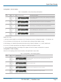
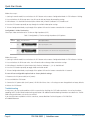
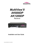
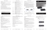
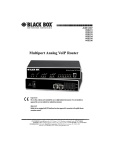
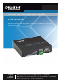
AC1003A-R2
CAT5 Multi VGA + Mono Audio Quad Transmitter
Quick Start Guide
BLACK BOX
®
Extend hi-res VGA video with audio or serial data as far as 2000 feet over
ordinary CAT5 cable.
Customer
Support
Information
AC1003A-R2 Quick Start Guide
Order toll-free in the U.S.: Call 877-877-BBOX (outside U.S. call 724-746-5500)
FREE technical support 24 hours a day, 7 days a week: Call 724-746-5500 or fax 724-746-0746
Mailing address: Black Box Corporation, 1000 Park Drive, Lawrence, PA 15055-1018
Web site: www.blackbox.com • E-mail: [email protected]
Quick Start Guide
Precautions
1. Do not apply AC power until instructed to do so.
2. This equipment is not intended for, nor does it support, distribution through an Ethernet network. Do not connect these
devices to any sort of networking or telecommunications equipment.
3. Use only Black Box approved power adapters. Failure to do so may damage the device and will void the warranty.
About the Transmitter
The CAT5 Multi VGA + Mono Audio Quad Transmitter extends an analog video signal over standard CAT5 cable (also CAT5e and
CAT6), provided over four link outputs. There are user-configurable settings for video, audio, and serial options that you can
control from the front panel. For more details, refer to the complete CAT5 Multi VGA + Mono Audio Quad Transmitter User
Manual.
Required Tools/Hardware/Materials: Tools include appropriate screwdriver(s) and mounting hardware (optional, for example:
rackmount, wall or under-desk mounting). Required materials include appropriate cables for your specific application.
NOTE: (Optional) Depending on installation requirements: At any time during installation, the transmitter may be securely
mounted using appropriate brackets and hardware.
What’s Included
Your package should contain the following items. If anything is missing or damaged, contact Black Box Technical Support
at 724-746-5500 or [email protected].
• (1) Transmitter
• (1) External Power Supply
• (1) U.S. Power Cord
• This user’s manual
Hardware Description
Figures 1 and 2 show the front and back panels of the transmitter. Table 1 describes its components.
1
2
3
456
7
8 9
Figure 1. Front panel.
10
11
12
13
14
Figure 2. Back panel.
Page 2
724-746-5500 | blackbox.com
AC1003A-R2 Quick Start Guide
Quick Start Guide
Table 1. Front and back panel components.
Number
Component
Description
1
(1) COPY/CFG LED
In normal mode, the CFG indicator is off. In configuration mode, the CFG indicator is on or flashing.
2
(1) COPY/CFG button
In operating mode, Off = Normal.
3
(5) LEDs
A, B, C, D, E
4
(1) STD LED
Video status
5
(1) Local LED
Video status
6
(1) Copy LED
DDC copy
7
(1) DDC Mode/Sel button
Selects DDC mode.
8
(1) 4-position Phoenix
connector
Auxiliary signal out
9
(1) HD15 VGA connector
Local video output port (to display)
10
(1) HD15 VGA connector
Video input port (from source)
11
(1) 4-position Phoenix
connector
Auxiliary signal in
12
(4) RJ-45 connectors
(4) UTP (link) output ports
13
(1) Power LED
Lights on when power to the unit is on.
14
(1) barrel connector
5-VDC power input
Getting Started
STEP 1: Power-up check: After all signal and power cables are connected, apply AC power. The Power ON indicator should light.
If the video source is providing a valid VGA (RGB+HV) video signal, the Video Status indicator should also be ON (for any other
type of video signal, this status indicator will always be OFF. If a local monitor is attached, a video image should appear on the
monitor. If there is no image on the display, recheck all cables and make sure the display is turned ON.
STEP 2: Panel Controls (Refer to Figure 2): Two buttons, COPY/CFG and DDC MODE/SEL, are used to control the operating
modes of the transmitter. Several green LED Status indicator display current status. In Normal mode, the CFG indicator is OFF. In
Configuration mode, the CFG indicator is ON or flashing.
STEP 3: DDC Mode Selection: When the transmitter is operating in Normal mode (CFG indicator is OFF), you can quickly select
between three DDC operating modes simply by pressing the DDC mode button at any time.
• STD: Selects the DDC profile. Press the DDC mode button until the STD indicator (LED #6) is ON. The DDC profile is a default
set of common video resolutions. This is the factory default setting.
• LOCAL: Selects the DDC profile from a locally connected display. Press the DDC MODE button until the LOCAL indicator (LED
#7) is ON. The LOCAL mode does NOT store any DDC profile information inside the transmitter.
• COPY: Selects a previously stored copy of a DDC profile. Press the DDC MODE button until the COPY indicator (LED #8) is ON.
To use the COPY mode, a DDC profile must have already been read and stored into the transmitter.
AC1003A-R2 Quick Start Guide
724-746-5500 | blackbox.com
Page 3
Quick Start Guide
To perfom a DDC copy operation: Make sure the COPY mode is selected (LED #8 is ON). Next:
A. Connect a display to the LOCAL OUT port.
B. Press and hold the COPY button until the Copy Status indicator flashes three times, indicating a successful operation. If it only
flashes once, the operation failed and the previously stored DDC profile (if any) will remain unchanged.
STEP 4: Changing Internal Settings: In Configuration mode (CFG indicator is ON or flashing), the CFG and SEL buttons, plus
the LED indicators (#1–8) will allow you to change internal configuration settings. The changes are effective immediately and are
saved in non-volatile memory.
• To enter Configuration Mode 1: Press the CFG button once. The CFG indicator will turn ON. Once in this mode, the LED
indicators #1–8 will display the current settings as described in Tables 2 and 3.
• To enter Configuration Mode 2: Press the CFG button twice. The CFG indicator will flash. Once in this mode, the LED
indicators #1–8 will display the current settings as described in Tables 4 and 5.
• To exit Configuration Mode: Leave the buttons untouched for 10 seconds. The CFG indicator will turn OFF (Normal mode).
Config Mode 1: Sync Mode Options
The transmitter is factory-configured for autodetecting the proper sync mode (RepliSync-I normal/stretched). This mode is
generally compatible with all existing receiver products that support sync (if they are also using their factory-default settings).
However, some video sources may require a custom sync mode setting (especially at 1080p and 1920 x 1200 video resolutions).
For these cases, you can select one of the other available sync modes.
NOTE: Any connected receiver should generally be set to the same sync mode and may require other configuration adjustments
(such as sync polarity). Otherwise, you may not get a proper video display output at that receiver.
Table 2. Config Mode 1, sync-mode options.
Step
Number*
LED 1
LED 2
LED 3
1
dim
dim
dim
The transmitter will auto-detect the required sync mode (normal or stretched). This is the
factory default setting.
2
dim
dim
ON
Force sync “normal,” Horizontal sync, pulse encoding.
3
dim
ON
dim
Force sync “stretched,” Horizontal sync, pulse encoding.
4
dim
ON
ON
Force sync.
5
ON
dim
dim
Front-Panel View
Sync Mode Setting
Force fixed-sync mode.
NOTE: A compatible connected receiver must also be in fixed-sync mode and with H/V
polarities selected at the receiver.
Follow these steps*:
1. Starting in normal mode, press and release the CFG button once to access Configuration Mode 1. CFG indicator is ON.
2. Press and release the SEL button once. You will now be able to change sync mode settings.
3. LED indicators 1–3 should be lit (either dim or ON); all other indicators (LEDs 4–8) should be OFF.
4. Press the CFG button repeatedly to step through the available sync mode settings.
5. To leave Configuration Mode, step through all the options OR leave the buttons untouched for 10 seconds.
Page 4
724-746-5500 | blackbox.com
AC1003A-R2 Quick Start Guide
Quick Start Guide
Config Mode 1: 4th-Pair Modes
Table 3. Config Mode 1, 4th-pair operating mode options.
Step
Number*
LED 4
LED 5
LED 6
1
dim
dim
dim
4th-pair signals are disabled. This effectively “mutes” anything sent on the 4th pair.
Use this for diagnostics.
2
dim
dim
ON
Direct pass-through of 4th-pair wires. Use this for custom applications.
3
dim
ON
dim
External analog (L + R summed) audio. This is the factory default mode.
4
dim
ON
ON
External S/PDIF digital audio. Input impedance = 75 ohms.
5
ON
dim
dim
Simplex serial.
Front-Panel View
4th-Pair Operating Mode
Follow these steps*:
1. (starting in normal-mode) Press and release the CFG button once to access Configuration Mode 1. CFG indicator = on.
2. Press and release the SEL button twice. You will now be able to change 4th-pair option settings.
3. LED Indicators 4–6 should be illuminated (either DIM or ON); all others (Indicators 1–3, 7, and 8) should be off.
4. Press the CFG button repeatedly to step through the available 4th-pair option settings.
5. To leave Configuration Mode, step through all the options OR leave the buttons untouched for 10 seconds.
Config Mode 2: Video Coupling
Select AC or DC coupling, and DC-restore functions, to be applied to the input video.
Table 4. Config Mode 2, video coupling options.
Step
Number*
LED 1
LED 2
1
dim
dim
Auto-detect AC/DC coupling mode based on input signal. This is the factory
default mode.
3
dim
ON
Video input is DC coupled.
4
dim
ON
Video input is AC coupled. DC restore function is disabled.
5
ON
ON
Video input is AC coupled. DC restore function is enabled.
AC1003A-R2 Quick Start Guide
Front-Panel View
Video Options Mode
724-746-5500 | blackbox.com
Page 5
Quick Start Guide
Follow these steps*:
1. (starting in normal-mode) Press and release the CFG button twice to access Configuration Mode 2. CFG indicator = flashing.
2. Press and release the SEL button once. You will now be able to change video coupling settings.
3. LED Indicators 1–2 should be illuminated (either DIM or ON); all others (Indicators 3–8) should be off.
4. Press the CFG button repeatedly to step through the available video option settings.
5. To leave Configuration Mode, step through all the options OR leave the buttons untouched for 10 seconds.
Config Mode 2: Video Termination
Select input video termination to be 75 ohms or high-impedance (Hi-Z).
Table 5. Config Mode 2, 75 ohms or high-impedance (Hi-Z) options.
Step
Number*
LED 3
1
dim
Video input impedance is Hi-Z.
2
ON
Video input impedance is 75 ohms. This is the factory default setting.
Front-Panel View
Video Options Mode
Follow these steps*:
1. (starting in normal-mode) Press and release the CFG button twice to access Configuration Mode 2. CFG indicator = flashing.
2. Press and release the SEL button twice. You will now be able to change video termination settings.
3. LED Indicator 3 should be lit (either DIM or ON); all others (Indicators 1, 2, 4–8) should be off.
4. Press the CFG button repeatedly to toggle video termination on/off.
5. To leave Configuration Mode, step through all the options OR leave the buttons untouched for 10 seconds.
To reset all user-configurable options back to factory default settings:
1. Disconnect the DC power cable (or AC power).
2. Press and hold the CFG button.
3. Connect the DC power cable (or AC power). All LEDs blink three times—all settings are now changed back to factory defaults.
4. Release the CFG button.
Troubleshooting
In many cases, you can resolve problems with the transmitter by checking the CAT5 cable termination. It must be pinned out
according to the TIA/EIA 568B standard wiring specification. For additional troubleshooting information or to obtain the TIA/EIA
568B wiring specifications, refer to the user manual.
If you have questions or problems with the transmitter, contact Black Box Technical Support at 724-746-5500
or [email protected].
Page 6
724-746-5500 | blackbox.com
AC1003A-R2 Quick Start Guide
NOTES
AC1003A-R2 Quick Start Guide
724-746-5500 | blackbox.com
Page 7
Black Box Tech Support: FREE! Live. 24/7.
Tech support the
way it should be.
Great tech support is just 30 seconds away at 724-746-5500 or blackbox.com.
About Black Box
Black Box provides an extensive range of networking and infrastructure products. You’ll find everything from cabinets and racks
and power and surge protection products to media converters and Ethernet switches all supported by free, live 24/7 Tech Support
available in 30 seconds or less.
© Copyright 2012. Black Box Corporation. All rights reserved. Black Box® and the Double Diamond logo are registered trademarks of BB Technologies, Inc.
Any third-party trademarks appearing in this manual are acknowledged to be the property of their respective owners.
AC1003A-R2 Quick Start Guide version 1
724-746-5500 | blackbox.com