1
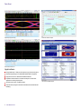
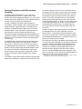
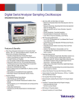
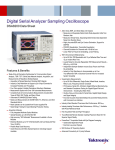
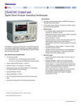
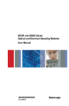
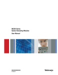
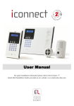
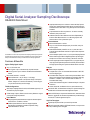
Digital Serial Analyzer Sampling Oscilloscope
DSA8300 Data Sheet
High Optical Sensitivity and Low Noise as well as the Wide Dynamic
Range of the Optical Sampling Modules allows Accurate Testing and
Characterization of Short-reach to Long-haul Optical Communications
Standards
Fully Calibrated Clock Recovery Solutions – No need to manually
calibrate for data pick-off losses
Calibrated Extinction Ratio Measurements ensure Repeatability of
Extinction Ratio Measurements to <0.5 dB among Systems with
Modules with this Factory Calibration Option
The DSA8300 is a state-of-the-art Equivalent Time Sampling Oscilloscope that provides
the highest fidelity measurement and analysis capabilities for Communications Signal
Analysis, Serial Data Network Analysis, and Serial Data Link Analysis applications.
Features & Benefits
Highest Fidelity Signal Capture
Very Low Time-base Jitter
425 fs Typical on up to 8 Simultaneously Acquired Channels
<200 fs Typical on up to 6 Channels with 82A04 Phase Reference
Module
Best Vertical Resolution – 16 bit A/D
Electrical Resolution: <20 µV LSB (for 1 V full range)
Optical Resolution depends on the Dynamic Range of the Optical
Module – Ranges from <20 nW for the 80C07B (1 mW full range) to
<0.6 µW for the 80C10B (30 mW full range)
Flexible Configurations
Electrical Modules
Electrical Bandwidths to >70 GHz
Very Low-noise Electrical Samplers (280 µV at 20 GHz, 450 µV at
60 GHz, typical)
Selectable Bandwidths (with 80E07, 08, 09, 10) allow the User to
Trade-off Sampler Bandwidth and Noise for Optimal Data Acquisition
Performance
Remote Samplers (80E07, 08, 09, 10) or Compact Sampling Extender
Module Cables support Minimal Signal Degradation by allowing the
Sampler to be Located in Close Proximity to the Device Under Test
World’s Highest-performance Integrated TDR (10 ps typical step rise
time) supports Exceptional Impedance Discontinuity Characterization
and High Dynamic Range for S-parameter Measurements to 50 GHz
Analysis
Standard Analysis Capabilities
Complete Suite of over 120 Automated Measurements for NRZ, RZ,
and Pulse Signal Types
Automated Mask Testing with over 80 Industry-standard Masks. New
Masks can be Imported into the DSA8300 to support New Emerging
Standards. In Addition, Users can Define their own Masks for
Automated Mask Testing
Vertical and Horizontal Histograms for Statistical Analysis of Acquired
Waveforms
Vertical, Horizontal, and Waveform Cursors (with measurements)
With Today’s Sampling Module Portfolio, the DSA8300 supports up to 8
Simultaneously Acquired Signals
Jitter, Noise, BER, and Serial Data Link Analysis is provided through the
80SJNB Basic and Advanced Software Application Options
A Wide Variety of Optical, Electrical, and Accessory Modules to support
your Specific Testing Requirements
Advanced TDR Analysis, S-parameter Measurements, Simulation Model
Extraction, and Serial Link Simulation Capabilities are provided through
the IConnect® Software Application Options
Optical Modules
Fully Integrated Optical Modules that support all Standard Optical
Data Rates from 155 Mb/s to 100 Gb/s
Certified Optical Reference Receivers Support Specified
Requirements for Standards-mandated Compliance Testing
Optical Bandwidths to >80 GHz
High Test Throughput
High Sample Acquisition Rate up to 300 kS/s per channel
Efficient Programmatic Interface (IEEE-488, Ethernet, or local processor
access) enable High Test Throughput
Data Sheet
Optical Eye Diagram Testing
Serial Data Network Analysis
Passive Interconnect Test
Applications
Design/Verification of Telecom and Datacom Components and Systems
Manufacturing/Testing for ITU/ANSI/IEEE/SONET/SDH Compliance
High-performance True-differential TDR Measurements
Impedance Characterization and Network Analysis for Serial Data
Applications including S-parameters
Advanced Jitter, Noise, and BER Analysis
Channel and Eye Diagram Simulation and Measurement-based SPICE
Modeling
2
www.tektronix.com
Jitter, Noise, and BER Analysis
Digital Serial Analyzer Sampling Oscilloscope — DSA8300
Superior Performance with Extraordinary
Versatility
The DSA8300 Digital Serial Analyzer is the most versatile tool for
developing and testing communications, computers, and consumer
electronics which utilize multi-gigabit data transmission. It is used for optical
and electrical transmitter characterization as well as compliance verification
for devices, modules, and systems used in these products.
In addition, the DSA8300 is well-suited for electrical signal path
characterization, whether for packages, PCBs, or electrical cables. With
exceptional bandwidth, signal fidelity, and the most extensible modular
architecture, the DSA8300 provides the highest-performance TDR and
interconnect analysis, most accurate analysis of signal impairments, and
BER calculations for current and emerging serial data technology.
Finally, with its exceptional signal fidelity and resolution, the DSA8300 is the
gold standard for electrical and optical applications which require ultra-high
bandwidths, very fine vertical resolution, low jitter, and/or exceptional time
interval accuracy.
The DSA8300 provides unmatched measurement system fidelity with the
lowest native instrument jitter floor (425 fs RMS, typical for serial data
signals at rates >1.25 Gb/s) that ensures the most accurate acquisition of
up to 8 high-bandwidth signals simultaneously. You get additional analysis
benefits from the 200 fs acquisition jitter with the Phase Reference module.
The multiprocessor architecture, with dedicated per-slot digital signal
processors (DSPs), provides fast waveform acquisition rates, reducing
the test times necessary for reliable characterization and compliance
verification.
The DSA8300’s versatile modular architecture supports a large and growing
family of plug-ins enabling you to configure your measurement system with
a wide variety of electrical, optical, and accessory modules that best suit
your application now and in the future. With 6 module slots, the DSA8300
can simultaneously accommodate a Clock Recovery module, a precision
Phase Reference module, and multiple acquisition modules, electrical or
optical, so you can match system performance to your evolving needs.
Featuring industry-leading signal fidelity, the family of electrical modules
includes bandwidth performance from 20 GHz to >70 GHz, while the optical
modules support optical testing from 125 Mb/s to 100 Gb/s and beyond
with optical bandwidth exceeding 80 GHz. The DSA8300 supports all
of the legacy 8000 Series electrical and optical sampling modules and
accessories*1.
In addition, specialized modules supporting features such as single-ended
and differential electrical clock recovery, electrostatic protection for
electrical samplers, and connectivity to the popular TekConnect® probing
system brings you the performance of state-of-the-art Tektronix probes for
high-impedance and differential probing. Low-impedance probes for 50 Ω
probing and for TDR probing are also available.
The raw acquisition performance of the DSA8300 and its sampling modules
and accessories is further augmented by the comprehensive measurement
and analysis capabilities of the DSA8300 and its associated software
applications. For example, the IConnect® software applications provide
complete TDR, S-parameter, and signal integrity analysis for passive
electrical interconnects (packages, printed circuit boards, backplanes,
cable, etc.) while the 80SJNB applications provide complete jitter, noise,
and bit error rate analysis as well as channel and equalization analysis and
emulation for both optical and electrical serial data links.
*1 The DSA8300 does not support the 80A06 Pattern Synchronization module as this capability is superseded
by the integrated Advance Trigger option (Option ADVTRIG) for the DSA8300.
www.tektronix.com
3
Data Sheet
Jitter, Noise, BER, and Serial Data Link
Analysis
80SJNB Jitter and Noise Analysis Measurements
High-speed serial data link measurements and analysis are supported
with three software solutions: 80SJARB, 80SJNB Essentials, and 80SJNB
Advanced.*2
Measurement
Description
TJ at BER
J2
J9
RJ
RJ(h)
RJ(v)
RJ(d-d)
DJ
DDJ
DDPWS
DCD
DJ(d-d)
PJ
PJ(h)
PJ(v)
EO at BER
BUJ
NPJ
SSCMagnitude
SSCFrequency
Total jitter at specified BER
Total jitter for BER = 2.5e–3
Total jitter for BER = 2.5e–10
Random jitter
Horizontal component of random jitter
Vertical component of random jitter
Random jitter according to the Dual Dirac model
Deterministic jitter
Data-dependent jitter
Data-dependent pulse width shrinkage
Duty cycle distortion
Deterministic jitter computed in the Dual Dirac model
Periodic jitter
Horizontal component of periodic jitter
Vertical component of periodic jitter
Horizontal eye opening at specified BER
Bounded uncorrelated jitter
Non-periodic jitter (uncorrelated and bounded)
Magnitude of SSC modulation in ppm
Frequency of SSC modulation in ppm
80SJARB (Option JARB) is a basic jitter measurement tool capable of
measuring jitter on any waveform – random or repetitive. The simplicity
of acquisition limits the amount of analysis possible so only the simplest
decomposition can be used; repeatability is pattern dependent
80SJNB Essentials (Option JNB) offers complete analysis of jitter, noise,
and BER, with decomposition of components for clear understanding of
a signal’s problems and margins. The acquisition methodology requires
a repetitive pattern. Both accuracy and repeatability are improved
relative to 80SJARB since the tool has access to the complete signal
pattern
80SJNB Advanced (Option JNB01) adds features to 80SJNB Essentials
for serial data link analysis – de-embedding of fixture, channel emulation,
FFE/DFE equalization, and pre-emphasis/de-emphasis
Jitter Analysis of Arbitrary Data (80SJARB)
The 80SJARB jitter measurement application software for the DSA8300
Series addresses IEEE 802.3ba applications requiring the J2 and J9
jitter measurements. It also enables basic jitter measurements for NRZ
data signals including PRBS31, random traffic, and scrambled data. This
provides an entry-level jitter analysis capability with simple Dual Dirac model
jitter analysis and no pattern synchronization requirement. 80SJARB can
acquire continuously in Free Run mode, delivering acquisitions and updates
beyond the IEEE minimum requirement of 10,000 data points. Plots include
jitter bathtub curves for both measured and extrapolated data, as well as a
histogram of the acquired data.
80SJARB Jitter Analysis
Measurement
Description
J2
J9
Tj
DJdd
RJdd
Total jitter for BER = 2.5e–3
Total jitter for BER = 2.5e–10
Total jitter for BER = 1.0e–12
Deterministic jitter (Dual Dirac model)
Random jitter (Dual Dirac model)
Free Run Mode: For continuous acquisitions and updates beyond the IEEE
minimum requirement of 10,000 data points.
Plots: Jitter / Eye Opening Bathtub, Histogram of Acquired Data.
80SJNB Jitter Analysis
80SJNB Noise Analysis
Measurement
Description
RN
RN(v)
RN(h)
DN
DDN1
DDN0
PN
PN(v)
PN(h)
EO at BER
BUN
NPN
Random noise
Vertical component of random noise
Horizontal component of random noise
Deterministic noise
Data-dependent noise on logical level 1
Data-dependent noise on logical level 0
Periodic noise
Vertical component of periodic noise
Horizontal component of periodic noise
Vertical eye opening at specified BER
Bounded uncorrelated noise
Non-periodic noise
80SJNB Advanced Supports:
FFE (Feed Forward Equalization) to 100 Taps
DFE (Decision Feedback Equalization) to 40 Taps
Filter for support of linear filters from fixture de-embed to transmitter
equalization. Channel emulation supported for channels with >30 dB
of loss at 1st harmonic frequency
*2 These software applications can be purchased to install on currently owned DSA8300 oscilloscopes with the
DSA83UP upgrade kits.
4
www.tektronix.com
Digital Serial Analyzer Sampling Oscilloscope — DSA8300
TDR (Time Domain Reflectometry)
Applications
The DSA8300 is the industry’s highest-performance fully integrated
Time Domain Reflectometry (TDR) measurement system. Offering
true-differential TDR measurements up to 50 GHz bandwidth with 15 ps
reflected rise time and 12 ps incident rise time*3, the DSA8300 enables you
to keep pace with today’s most demanding Serial Data Network Analysis
(SDNA) requirements.
The 80E10 and 80E08 TDR modules feature a fully integrated independent
dual-channel 2-meter remote sampler system to minimize fixturing and
assure optimal system fidelity. Independent sampler deskew ensures fast
and easy fixture and probe de-embedding. The user can characterize
differential crosstalk by using TDR steps from a differential module to drive
one line pair while monitoring a second line pair with a second differential
module.
The DSA8300 is the industry’s most versatile TDR measurement system,
accommodating up to 4 dual-channel true-differential TDR modules for fast,
accurate multilane impedance and S-parameter characterization.
Quickly identify the exact location of faults with the 80E10 sub-millimeter resolution and
IConnect® True Impedance Profile.
The P80318 True-differential TDR probe and P8018 Single-ended Passive
Handheld TDR probe provide high-performance probing solutions for circuit
board impedance and electrical signal characterization. The P80318, an
18 GHz 100 Ω input-impedance differential TDR hand probe, enables
high-fidelity impedance measurements of differential transmission lines.
The adjustable probe pitch enables a wide variety of differential line spacing
and impedances. The P8018 is a 20 GHz Single-ended Passive Handheld
TDR probe. Both the P80318 and P8018 can be used as stand-alone
probes but are especially designed to work with the 80A02 for the control of
EOS/ESD protection.
TDR Module Performance with IConnect®
*3 Rise times are 10-90%. Typical reflected rise times for the 80E10 are <10 ps.
When you employ IConnect® Signal Integrity TDR and S-parameter
software with the DSA8300 you have an efficient, easy-to-use, and
cost-effective solution for measurement-based performance evaluation
of multi-gigabit interconnect links and devices, including signal integrity
analysis, impedance, S-parameter, and eye-diagram tests, and fault
isolation. IConnect® can help you complete interconnect analysis tasks in
minutes instead of days, resulting in faster system design time and lower
design costs. IConnect® also enables impedance, S-parameters, and
eye-diagram compliance testing as required by many serial data standards,
as well as full channel analysis, Touchstone (SnP) file output, and SPICE
modeling for multi-gigabit interconnects.
Multi-gigabit Signal Path Characterization
and Analysis – Serial Data Network Analysis
(SDNA)
As clock speeds and rise times of digital circuits increase, interconnect
signal integrity dramatically affects digital system performance. Accurate
and efficient Serial Data Network Analysis (SDNA) of the signal path and
interconnects in time and frequency domains is critical to predict signal
losses, jitter, crosstalk, terminations and ringing, digital bit errors, and eye
diagram degradation, ensuring reliable system operation.
Tektronix offers several true-differential TDR modules, which in combination
with IConnect® software allow S-parameter measurements with up to
–70 dB of dynamic range. This performance assures accurate, repeatable
measurements in serial data analysis, digital design, signal integrity, and
electrical compliance testing applications.
TDR Module
S-parameter Measurement Bandwidth
Performance
80E10
80E08
80E04
50 GHz
30 GHz
20 GHz
With the long record length acquisitions, IConnect® provides great flexibility
for obtaining the desired frequency range and frequency step when
performing S-parameter measurements. Up to 1,000,000 points can be
acquired.
Failure Analysis – Quickly Identify Fault
Location
The 80E10, with its 12 ps typical TDR rise time, provides superior resolution
enabling the fastest and most efficient fault isolation in package, circuit
board, and on-chip failure analysis applications.
www.tektronix.com
5
Data Sheet
IConnect® Signal Integrity TDR and
S-parameter Software
Operating on the DSA8300 TDR platform, IConnect® S-parameters is
the most cost-effective and highest throughput approach for S-parameter
measurements in digital design, signal integrity analysis, and interconnect
compliance testing, providing as much as 50% cost savings compared to
similar bandwidth VNAs, and dramatically speeding up measurements.
You can also take advantage of the IConnect® S-parameters command-line
interface, which automates the S-parameter measurements to the overall
suite of manufacturing tests you perform using your TDR instrument,
significantly reducing test time while increasing measurement repeatability.
The simplicity of S-parameter calibration using a reference (open, short,
or through), and an optional 50 Ω load makes measurements, fixture
de-embedding, and moving the reference plane a snap. Touchstone
file format output enables easy S-parameter file sharing for further data
analysis and simulations.
Tektronix offers several true-differential TDR modules, which in combination
with IConnect® offers S-parameter measurements up to 50 GHz with up
to –70 dB of dynamic range. This performance exceeds requirements
6
www.tektronix.com
for serial data analysis, digital design, and signal integrity applications,
resolving down to 1% (–40 dB) accuracy of crosstalk, while electrical
compliance testing masks typically call for measurements in the –10 to
–30 dB range.
IConnect® software allows you to quickly and easily generate SPICE and
IBIS models for your PCBs, flex boards, connectors, cables, packages,
sockets, and I/O buffer inputs directly from TDR/T or VNA S-parameter
measurements
IConnect® allows you to display eye diagram degradation, jitter, loss,
crosstalk, reflections, and ringing in your digital system
IConnect® Linear Simulator allows the designer to link several
interconnect channels together to evaluate the total time, frequency
domain performance, and eye diagram of the overall channel
IConnect® substantially simplifies the signal integrity analysis of the
interconnect link, equalization and emphasis component design, and
analysis of the interconnect link with transmitter and receiver
For more information regarding the IConnect® software applications, see
the “IConnect® Signal Integrity, TDR, and S-Parameter SW – 80SICMX •
80SICON • 80SSPAR” data aheet.
Digital Serial Analyzer Sampling Oscilloscope — DSA8300
High-speed Optical Test Solutions
The DSA8300 with its highly configurable mainframe and a wide variety of
optical modules provide complete optical test solutions with superior system
fidelity from 125 Mb/s to 100 Gb/s and beyond. The modules cover a range
of wavelengths for both single- and multi-mode fibers. Each module can
be optionally configured with a number of selectable Optical Reference
Receiver (ORR) filters and/or a full bandwidth path. Each module also
supports fully calibrated clock recovery solutions (whether integrated into
the module or through a data pick-off routed to an external clock recovery
module or stand-alone clock recovery instrument).
Shown below is a brief description of each available optical sampling
module as well as a selection guide with the key specifications for each
module. For more complete information on these modules, see the “Optical
Sampling Modules – 80C07B • 80C08C • 80C10B • 80C11 • 80C12B •
80C25GBE” data sheet.
Optical Sampling Modules
Module
Description
80C07B Multirate Datacom and Telecom
The 80C07B module is a broad-wavelength (700 to 1650 nm) multirate optical sampling module optimized for testing
datacom/telecom signals from 125 Mb/s to 2.5 Gb/s. With its amplified O/E converter design, this module provides excellent
signal-to-noise performance, allowing users to examine low-power optical signals. The 80C07B can be optionally configured with
fully calibrated internal clock recovery that supports 125, 155, 622, 1063, 1250, 2125, 2488, 2500, and 2666 Mb/s rates.
80C08C Multirate, Broad Wavelength, High The 80C08C module is a broad-wavelength (700 to 1650 nm) multirate optical sampling module providing datacom rate testing
Sensitivity 10 Gb/s
for 10GbE, 40GbE-R4, 100GbE-SR10 applications at 9.953, 10.3125, 11.0957 Gb/s and 10G Fibre Channel applications at
10.51875 and 11.317 Gb/s. The 80C08C also provides telecom rate testing at 9.953, 10.664, and 10.709 Gb/s. With its amplified
O/E converter design, this module provides excellent signal-to-noise performance and high optical sensitivity, allowing users to
examine low power level optical signals. The 80C08C can be optionally configured with an integrated clock recovery option that
supports acquiring signals at any standard- or user-specified rate from 9.8 to 12.6 Gb/s.
80C10B Multirate Datacom and Telecom
The 80C10B module provides integrated and selectable-reference receiver filtering, enabling conformance testing at either
40 Gb/s and 100 Gb/s
1310 or 1550 nm for 39.813 Gb/s (OC-768/STM-256, VSR2000 G.693, 40G NRZ G.959.1), 41.25 Gb/s (40GBASE-FR),
and 43.018 Gb/s [G.709 FEC, OTU3, (4×10G LAN PHY)] rates. In addition to these rates, the user may also choose
selectable bandwidths of 30, 65, and 80 GHz on the 80C10B for optimal noise vs. bandwidth performance and accurate signal
characterization. Option F1 for the 80C10B extends filter selections to include 27.739 Gb/s (100GBASE-LR4 + FEC and
100GBASE-ER4 + FEC) and 25.781 Gb/s (100GBASE-LR4 and 100GBASE-ER4 ). When equipped with Option CRTP, an
electrical signal pick-off is provided for clock recovery. Clock recovery to 28.6 Gb/s for the 80C10B is provided using the CR286A
clock recovery instrument (sold separately). The 80C10B is also optionally available in a bundled ordering configuration which
includes a 70+ GHz electrical sampling channel.
80C11 Multirate 10 Gb/s Datacom and
The 80C11 module is a long-wavelength (1100 to 1650 nm) multirate optical sampling module optimized for testing 10 Gb/s
Telecom
datacom and telecom standard rates at 9.953, 10.3125, 10.51875, 10.664, 10.709, 11.0957, 11.317, and 14.025 Gb/s. With its
high optical bandwidth of up to 30 GHz (typical) it is well-suited for general-purpose high-performance 10 Gb/s optical component
testing. The 80C11 can be optionally configured with clock recovery that can support any standard or user-defined rate in the
continuous range from 9.8 to 12.6 Gb/s.
80C12B Multirate Datacom and Telecom
The 80C12B module is a broad wavelength (700 to 1650 nm) multirate optical sampling module providing telecom and datacom
testing for standards from 155 Mb/s to 11.4 Gb/s. This highly flexible module can be configured to support a wide variety of
10 Gb/s applications, lower data rate applications (155 Mb/s to 7.4 Gb Gb/s), or a combination of 10G and lower data rate
standards.
The low data rate applications include: Telecom applications from 155 to 2666 Mb/s, 1G, 2G, and 4G Fibre Channel, multilane
standards such as 10GBASE-X4 and 4-Lane 10 Gb/s Fibre Channel, and Infiniband SDR and DDR rates.
The supported 10 Gb/s application includes both datacom and telecom standards. The supported 10 Gb/s datacom applications
include 10GbE, 40GbE-R4, 100GbE-SR10 applications at 9.953, 10.3125, 11.0957 Gb/s, and 10G Fibre Channel applications at
10.51875 Gb/s and 11.317 Gb/s. The 80C12B also provides telecom rate testing at 9.953, 10.664, and 10.709 Gb/s.
With its amplified O/E converter design, this module provides excellent signal-to-noise performance and high optical sensitivity,
allowing users to examine low-power optical signals. Clock recovery for the 80C12B is provided using the 80A05 module or
CR125A clock recovery instrument (sold separately).
80C14 Multirate Datacom and Telecom
The 80C14 module is a broad-wavelength (700 to 1650 nm) multirate optical sampling module providing 8G, 10G, and 16G
telecom and datacom testing. The supported 10 Gb/s datacom applications include: 10GbE, 40GbE-R4, 100GbE-SR10
applications at 9.953, 10.3125, and 11.0957 Gb/s. Fibre Channel applications include: 8.500, 10.51875, 11.317, and 14.025 Gb/s.
The 80C14 also provides telecom rate testing at 9.953, 10.664, 10.709, and 12.5 Gb/s.
With its amplified O/E converter design, this module provides excellent signal-to-noise performance and high optical sensitivity,
allowing users to examine low power level optical signals. Clock recovery for the 80C14 is provided by the CR175A or CR286A
(sold separately).
80C25GBE Multirate Datacom
The 80C25GBE module provides 65 GHz full-bandwidth, integrated, and selectable-reference receiver filtering, enabling
100 Gb/s (4 × 25 Gb/s)
conformance testing at either 1310 or 1550 nm for 27.739G (100GBASE-LR4+FEC and 100GBASE-ER4+FEC) and 25.781G
(100GBASE-LR4 and 100GBASE-ER4). When equipped with Option CRTP an electrical signal pick-off is provided for clock
recovery. Clock recovery for the 80C25GBE is provided using the CR286A clock recovery instrument (sold separately).
www.tektronix.com
7
Data Sheet
Optical Sampling Module Selection Guide
In the table below is shown the key specifications for each of the current optical sampling modules available for use with the DSA8300 to assist you in selecting the optical
module(s) most appropriate for your optical testing application. Detailed specifications are available in the 80Cxx Optical Sampling Modules data sheet.
Characteristic
80C07B*4
80C08C
Wavelength
700-1650
700-1650
Range (nm)
2.5
10
Unfiltered
Optical
Bandwidth
(GHz)
Fiber Input
9, 50, 62.5
9, 50, 62.5
(µm)
–22
Mask Test
–16*8
Sensitivity
(dBm)
Optical Reference Receivers Supported
■
155 Mb/s
■
622 Mb/s
■
1.063 Gb/s
■
1.250 Gb/s
■
2.125 Gb/s
■
2.488 Gb/s
■
2.500 Gb/s
2.66 Gb/s
3.125 Gb/s
3.188 Gb/s
4.250 Gb/s
5.000 Gb/s
6.144 Gb/s
7.373 Gb/s
8.500 Gb/s
9.953 Gb/s
10.31 Gb/s
10.51 Gb/s
10.66 Gb/s
10.71 Gb/s
11.1 Gb/s
11.3 Gb/s
14.025 Gb/s
14.063 Gb/s
25.78 Gb/s
27.74 Gb/s
39.81 Gb/s
41.25 Gb/s
43.02 Gb/s
80C12B*5
80C14
80C11
Opt. F0-F12
Opt.
10G/10GP
700-1650
700-1650
700-1650
1100-1650
12*7
12*7
12
9, 50, 62.5
9, 50, 62.5
–19
Opt. F1
30
1290-1330
1520-1620
65
1290-1330
1520-1620
80
1290-1330
1520-1620
65
9, 50, 62.5
9
9
9
9
–15
–15
–9
–8*9
–7*9
–8*9
■
■
■
■
■
■
■
■
■
■
■
■
■
■
■
■
■
■
■
■
■
■
■
■
■
■
■
■
■
■
■
■
■
■
■
■
■
■
■
■
■
■
■
■
■
■
■
■
■
■
■
■
■
■
■
■
■
*4 There are specific reference receiver groupings supported for the 80C07B, see the 80Cxx Optical Module data sheet for detailed information.
*6 The clock recovery trigger pick-off (Option CRTP) for the 80C10B can support trigger pick-off for data rates to >43 Gb/s.
*7 The full 12 GHz bandwidth for the 80C12B is only available with Option F0, 10G, or 10GP.
*8 Mask test sensitivity of the 80C08C reduced by ~1 dBm with internal clock recovery options.
*9 Mask test sensitivity of the 80C10B and 80C25GBE reduced by ~0.6 dBm with internal clock recovery trigger pick-off (Option CRTP).
www.tektronix.com
80C10B*6
Std.
*5 There are specific reference receiver groupings supported for the 80C12B, see the 80Cxx Optical Module data sheet for detailed information.
8
80C25GBE
■
■
Digital Serial Analyzer Sampling Oscilloscope — DSA8300
Clock Recovery for Optical Testing
specifications for each solution to assist you in selecting the solution(s)
most appropriate for your application. For more detailed information on
these solutions, see the 80Cxx Optical Sampling Modules data sheet (for
clock recovery options integrated into the 80C07B, 80C08C, or 80C11) or
the appropriate clock recovery data sheets for stand-alone clock recovery
modules or instruments.
In many optical applications, there is no data clock directly available to
provide a reference signal for acquiring the signals from the device under
test. In these situations, it is necessary to recover the clock from the data
signal. The Tektronix 8000 Series of sampling oscilloscope products
provides a complete complement of clock recovery solutions to meet this
need. Each of these solutions is fully calibrated so that users do not need
to do any manual calibration of the system to take into account any losses
due to data pick-off being routed to the input of the clock recovery unit.
Shown below is a clock recovery solutions selection guide with the key
Note: The stand-alone clock recovery modules/instruments have electrical
inputs and can be used to recover clocks from electrical signals as well
as from the electrical data pick-off outputs from the 8000 Series optical
sampling modules.
Integrated Clock Recovery Options*10
Characteristic
80C07B
80C11
Opt. CR1
Opt. CR2
Opt. CR4
Opt. CR1
Opt. CR2
Opt. CR3
Opt. CR4
Fixed Rates
Fixed Rates
Fixed Rates
9.8 - 12.6
Fixed Rates
Fixed Rates
Fixed Rates
9.8 - 12.6
–15
–15
–15
–9
–9
–9
–9
■
■
■
■
■
■
■
■
■
■
■
■
■
■
■
■
■
Continuously
Variable Rate
Range (Gb/s)
–22
Clock Recovery
Sensitivity
(dBm)*11
Standard Rates Supported
■
125, 155 Mb/s
■
622 Mb/s
■
1063 Mb/s
■
1250 Mb/s
■
2125 Mb/s
■
2488, 2500 Mb/s
9.95 Gb/s
10.31 Gb/s
10.52 Gb/s
10.66 Gb/s
10.71 Gb/s
11.1 Gb/s
11.3 Gb/s
14.025 Gb/s
14.063 Gb/s
25.78 Gb/s
27.74 Gb/s
80C08C
Opt. CR1
■
■
■
■
■
■
*10 Clock recovery is integrated into the optical module and controllable from the Trigger Setup menu of the 8000 Series scope.
*11 Electrical clock recovery sensitivity is for differential input and varies with the input clock rate. See clock recovery data sheets for more information.
www.tektronix.com
9
Data Sheet
Stand-alone (Electrical) Clock Recovery Modules/Instruments
Characteristic
Continuously Variable Rate
Range (Gb/s)
Clock Recovery Sensitivity
(mVp-p)*11
Adjustable Clock Recovery
Loop Bandwidth and
Peaking*14
Standard Rates Supported
125, 155 Mb/s
622 Mb/s
1063 Mb/s
1250 Mb/s
2125 Mb/s
2488, 2500 Mb/s
2.66 Gb/s
3.125, 3.188 Gb/s
4.25 Gb/s
5.00 Gb/s
6.14 Gb/s
7.37 Gb/s
8.50 Gb/s
9.95 Gb/s
10.31 Gb/s
10.52 Gb/s
10.66 Gb/s
10.71 Gb/s
11.1 Gb/s
11.3 Gb/s
14.025 Gb/s
14.063 Gb/s
25.78 Gb/s
27.74 Gb/s
80A05*12
Std.
Opt. 10G
50 - 3.188, 4.25
50 - 3.188, 3.267 - 4.25,
4.900 - 6.375, 9.8 - 12.6
≤15
≤15
■
■
■
■
■
■
■
■
■
■
■
■
■
■
■
■
■
■
■
■
■
■
■
■
■
■
■
■
■
■
■
■
CR125A*13
CR175A*13
CR286A*13
0.1 - 12.5
0.1 - 17.5
0.1 - 28.6
15
15
15
■
■
■
■
■
■
■
■
■
■
■
■
■
■
■
■
■
■
■
■
■
■
■
■
■
■
■
■
■
■
■
■
■
■
■
■
■
■
■
■
■
■
■
■
■
■
■
■
■
■
■
■
■
■
■
■
■
■
■
■
■
■
■
■
■
■
■
■
■
■
■
*11 Electrical clock recovery sensitivity is for differential input and varies with the input clock rate. See clock recovery data sheets for more information.
*12 The clock recovery module plugs into one of the 8000 Series scope's large module slots and is controllable from the Trigger Setup menu.
*13 Stand-alone clock recovery instrument; controllable from the BERTScope clock recovery instrument control application, accessible from the App menu of the 8000 Series scope.
*14 For more information on clock recovery loop bandwidth and peaking, see clock recovery data sheets.
Measurement and Analysis Tools for Optical
Testing Applications
The DSA8300 includes a wide variety of measurement and analysis tools
which specifically address optical testing applications. In addition to the
standard amplitude and timing parametric measurements (e.g. rise/fall
times, amplitude, RMS jitter, RMS noise, frequency, period, etc.) the
measurement suite for the DSA8300 includes measurements specifically
tailored to measuring optical signals (average optical power, extinction ratio,
eye height, eye width, optical modulation amplitude (OMA), etc.). For a
complete list of measurements, see the Math/Measurement section of this
data sheet.
10
www.tektronix.com
The DSA8300 also includes standard compliance testing masks for all
of the common optical standards from 155 Mb/s to 100 Gb/s. Users can
also create their own masks for automated mask testing. Histograms and
cursor measurements are also available to analyze optical signals acquired
by the DSA8300.
Finally, the 80SJNB applications support complete jitter, noise, and BER
analysis for optical signals. The advanced version of this software (Option
JNB01) supports evaluating the emphasis and equalization on impaired
signals.
Digital Serial Analyzer Sampling Oscilloscope — DSA8300
High-performance Electrical Test Solutions
sampling modules available for use with the DSA8300 to assist you in
selecting the electrical module(s) most appropriate for your application.
Detailed specifications are available in the 80Exx Electrical Sampling
Modules data sheet.
The DSA8300 is also well-suited for a variety of high-performance electrical
applications. With the modular system, users can configure their DSA8300
with a variety of electrical modules that are best suited to their requirements.
In the table below is the key specifications for each of the current electrical
Electrical Sampling Module Selection Guide
Characteristic
Channels
Bandwidth
Step Response
at Full Bandwidth
(10-90%)
RMS Noise
Incident TDR
Step Rise Time
(10-90%)
Reflected TDR
Step Rise Time
(10-90%)
Remote Sampling
Capability
80E01
80E03
80E06
1
50 GHz
2
20 GHz
1
70+ GHz
7 ps
17.5 ps
5.0 ps
1.8 mV
600 µV
1.8 mV
—
—
—
—
—
—
w/ optional 2 m
80N01 extender
cable
w/ optional 2 m
80N01 extender
cable
w/ optional 2 m
80N01 extender
cable
80E07
80E09
TDR Modules
80E04
80E08
80E10
2
30/40/60 GHz
(user selectable)
5.8 ps
2
20 GHz
2
20/30 GHz
(user selectable)
11.7 ps
2
30/40/50 GHz
(user selectable)
7 ps
280 µV at 20 GHz 300 µV at 30 GHz
300 µV at 30 GHz 330 µV at 40 GHz
450 µV at 20 GHz
—
—
600 µV
2
20/30 GHz
(user selectable)
11.7 ps
—
—
Fully integrated Fully integrated
2 m remote cable 2 m remote cable
17.5 ps
23 ps
28 ps
w/ optional 2 m
80N01 extender
cable
280 µV at 20 GHz 300 µV at 30 GHz
300 µV at 30 GHz 370 µV at 40 GHz
600 µV at 60 GHz
18 ps
12 ps
20 ps
15 ps
Fully integrated Fully integrated
2 m remote cable 2 m remote cable
www.tektronix.com
11
Data Sheet
S-parameter Performance Characteristics (80E10)
Measurement Conditions
All measurements were performed after proper warm up as specified in
the DSA8300 manual
Standard S-parameter dynamic range measurement practices were
used to determine the dynamic range of the module
Uncertainty results were derived from a wide range of devices, with
250 averages
Better dynamic range can be achieved by selecting lower bandwidth
settings on the 80E10 module due to a lower RMS noise floor
Results apply to single-ended or differential measurements
Dynamic Range
12
www.tektronix.com
Uncertainty
Digital Serial Analyzer Sampling Oscilloscope — DSA8300
Specifications
Product specifications and descriptions in this document are subject to change
without notice.
Signal Acquisition
Characteristic
Description
Acquisition Modes
Number of
Sampling Modules
Accommodated
Sample (Normal), Envelope, and Average
Up to 4 dual-channel electrical; up to 2 optical sampling
modules. (Both single- and dual-channel modules are
appropriate for the two channels associated with the slot)
Population of the CH1/CH2 large slot with any module other
than one requiring power only displaces functionality of
the CH1/CH2 small slot; population of the CH3/CH4 large
slot with any module other than one requiring power only
displaces functionality of the CH3/CH4 small slot
8 channels maximum
Number of
Simultaneously
Acquired Inputs
Maximum
Acquisition Rate
Vertical Systems
Rise Time /
Bandwidth
Vertical
Resolution
300 kS/s per channel in TDR mode; 200 kS/s per channel in
all other non-phase reference modes; 120 kS/s per channel
in phase reference modes
Determined by the sampling modules used
16 bits over the sampling modules' dynamic range
Electrical Resolution: <20 µV LSB (for 1 V full range)
Optical resolution depends on the dynamic range of the
optical module – ranges from <20 nW for the 80C07B (1 mW
full range) to <0.6 µW for the 80C10B (30 mW full range)
Horizontal System
Main and
100 fs/div to 1 ms/div in 1-2-5 sequence or 100 fs increments
Magnification
View Time
Bases, Horizontal
Scale
Time Interval Accuracy
Trigger Direct Horizontal scale >20 ps/div, right-most point of measurement
(Front Panel) interval <150 ns; Mean Accuracy: 0.1% of interval, STDEV:
Input
≤1 ps
Horizontal scale ≤20 ps/div, right-most point of measurement
interval <150 ns; Mean Accuracy: 1 ps + 0.5% of interval
Mean accuracy determined by clock input accuracy
Clock
Input/Prescale STDEV: <0.7 ps (max); <0.1 ps (typical)
Trigger (Front
Panel), Eye or
Pattern Mode
Characteristic
Clock
Input/Prescale
Trigger (Front
Panel), Other
Mode
TDR Clock
Trigger (Lock
to External
10 MHz Clock)
Random
Phase
Corrected
Mode*15
(Clock Input
to 82A04)
Triggered
Phase
Corrected
Mode (Clock
Input to
82A04)
Horizontal
Deskew Range
Available*16
DSA8300 Record
Length
Description
Horizontal scale >20 ps/div, right-most point of measurement
interval <150 ns; Mean Accuracy: 0.1% of interval, STDEV:
≤3 ps
Horizontal scale ≤20 ps/div, right-most point of measurement
interval <150 ns; Mean Accuracy: 1 ps + 0.5% of interval
Horizontal scale >20 ps/div, right-most point of measurement
interval <150 ns; Mean Accuracy: 0.01% of interval, STDEV:
≤1 ps (0.1 ps typical)
Maximum timing deviation 0.1% of phase reference signal
period, typical, relative to phase reference signal
Maximum timing deviation relative to phase reference signal:
>40 ns after trigger event: 0.2% of phase reference signal
period, typical
≤40 ns after trigger event 0.4% of phase reference signal
period, typical
–500 ps to +100 ns on any individual channel in 100 fs
increments
50, 100, 250, 500, 1000, 2000, 4000, 8000, or
16000 samples (magnification views have maximum record
length of 4000 samples)
Longer Records IConnect®: 1M samples
Available
80SJNB Jitter, Noise, and BER Analysis Software:
10M samples (100k unit intervals, 100 samples per unit
interval)
Waveform
4 independently accumulated waveform records of up to 4M
Databases
waveform points each. Variable waveform database mode
with true first-in/first-out of up to 2000 waveforms available
on each of 4 waveform databases (2M samples maximum
/ waveform database)
Magnification Views In addition to the main time base, the DSA8300 supports two
magnification views. These magnifications are independently
acquired using separate time-base settings which allow same
or faster time/div than that of the main time base
*15 For more information on phase reference modes of operation, see the “Phase Reference Module for the
DSA8300 Sampling Oscilloscope” data sheet.
*16 Mainframe slot deskew only – the 80E07, 80E08, 80E09, and 80E10 remote sampling modules include
additional channel deskew range.
www.tektronix.com
13
Data Sheet
Trigger System
Characteristic
Math/Measurement System
Description
Trigger Sources
Clock Input/Prescale Trigger (front panel)
TDR clock (generated internally)
Clock recovery triggers from Optical Sampling modules and
Electrical Clock Recovery modules (internally connected)
Phase Reference*17 time base supports acquisitions without
a trigger signal in its Free Run mode
Trigger Direct Input (front panel)
Clock Input / Prescale Trigger Input
Clock Input
100 mVp-p, 0.15 to 20 GHz (typical)
Sensitivity
200 mVp-p, 0.15 to 15 GHz (guaranteed)
Minimum Slew
≥2 V/ns
Rate
Clock Input
1.0 Vp-p (max) – AC coupled
Range
Pattern Lengths 2 to 223 (8,388,608) inclusive
Supported
(for Pattern
Triggering
with ADVTRIG
Option)
Clock Input Jitter 0.15 - 0.40 GHz: 900 fs (RMS)
in Clock-eye and 0.40 - 1.25 GHz: 800 fs
1.25 - 20 GHz: 425 fs
Clock-pattern
Trigger Modes
(Typical)
Clock Input Jitter 0.80 - 1.25 GHz: 900 fs (RMS)
in Clock-eye and 1.25 - 11.20 GHz: 500 fs
11.20 - 15.0 GHz: 600 fs
Clock-pattern
Trigger Modes
(Max)
TDR Trigger
TDR Step Rate Selectable from 25 to 200 kHz in 1 kHz steps*18
TDR Trigger Jitter 1.3 ps RMS (typical)
1.8 ps RMS (max)
Phase Reference Time Base
Phase Reference Standard 82A04: 8 - 25 GHz (guaranteed), 2 - 25 GHz
Input Range*19
(typical)
82A04 Option 60G: 8 - 60 GHz (guaranteed), 2 - 70 GHz
(typical)
Phase Reference Best jitter performance is with the clock input to the 82A04 in
Input Sensitivity the following range: 0.6 - 1.8 V. The phase reference time
base remains operational to 100 mV (typical) with increased
jitter
Jitter
f ≥8 GHz: 200 fs RMS, typical on a 10 GHz or faster
sampling module
2 GHz ≤ f ≤ 8 GHz*19: 280 fs RMS, typical on a 10 GHz or
faster acquisition module
Trigger Direct Input
Trigger
50 mV, DC - 4 GHz (typical)
Sensitivity
100 mV, DC - 3 GHz (guaranteed)
Trigger Level
±1.0 V
Range
Trigger Input
±1.5 V
Range
Adjustable 5 µs to 50 ms in 0.5 ns increments
Trigger Holdoff
Trigger Direct
1.1 ps RMS + 5 ppm of horizontal position (typical)
Input Jitter
1.5 ps RMS + 10 ppm of horizontal position (max)
*17 When using the 82A04 Phase Reference module.
*18 Actual TDR step rate may vary by up to 2% from requested rate.
*19 For clock frequencies <8 GHz, it may be necessary to filter the clock input to eliminate harmonics from the
clock signal (see Other Accessories 020-2566-xx, 020-2567-xx, and 020-2568-xx).
14
www.tektronix.com
Characteristic
System
Measurements
Description
The DSA8300 supports up to 8 simultaneous measurements,
updated 3 times per second with optional display of
per-measurement statistics (min, max, mean, and standard
deviation)
Measurement Set Over 120 automated measurements include RZ, NRZ, and
pulse signal types, and the following measurement types:
Amplitude
High, Low, Amplitude, Peak-to-Peak, Max, Mid, Min, Mean,
Measurements +Overshoot, –Overshoot, P-P, Average Optical Power (dBm,
watts), Noise, RMS Noise, SNR, Eye Height, Eye Opening
Factor, Extinction Ratio (Ratio, %, dB), Suppression Ratio
(Ratio, %, dB), OMA, Q-factor, RMS, AC RMS, Cycle RMS,
Cycle Mean, Gain, Crossing %, Crossing Level
Timing
Rise, Fall, Period, Bit Rate, Bit Time, Frequency, Crossing
Measurements Time, +Cross, –Cross, Jitter (P-P, RMS), Eye Width, +Width,
–Width, Burst Width, +Duty Cycle, –Duty Cycle, Duty Cycle
Distortion, Delay, Phase, Pulse Symmetry
Area
Area, Cycle Area
Measurements
Dot, vertical bar, and horizontal bar cursors
Cursors
Waveform
Up to 8 math waveforms can be defined and displayed
Processing
using the following math functions: Add, Subtract, Multiply,
Divide, Average, Differentiate, Exponential, Integrate, Natural
Log, Log, Magnitude, Min, Max, Square Root, and Filter. In
addition, measurement values can be utilized as scalars in
math waveform definitions
Mask Testing
For many applications, standard masks are available as
predefined, built-in masks. Many of the most commonly used
standard masks are listed below. To get a list of all currently
available masks contact your local Tektronix representative
Unless otherwise noted, file-based masks are used to
distribute new, Tektronix factory-created, updated masks as a
file loadable by the firmware.
User-defined masks allow the user to create (through UI or
PI) user masks
Ethernet
100BASE-LX10 125.0 Mb/s
100BASE-BX10 125.0 Mb/s
Gigabit Ethernet 1.250 Gb/s
1000BASE-KX 1.250 Gb/s
2 GBE 2.500 Gb/s
10GBASE-X4 3.125 Gb/s
10GBASE-W 9.95328 Gb/s
10GBASE-R 10.3125 Gb/s
FEC11.10 11.095728 Gb/s
10GBASE-LRM 10.31250 Gb/s
40GBASE-FR 41.25 Gb/s
40GBASE-LR4 10.3125 Gb/s
40GBASE-SR4 10.3125 Gb/s
100GBASE-ER4 25.71825 Gb/s
100GBASE-LR4 25.71825 Gb/s
100GBASE-SR10 10.3125 Gb/s
Digital Serial Analyzer Sampling Oscilloscope — DSA8300
Characteristic
SONET/SDH
Fibre Channel
Optical
Fibre Channel
Electrical
SATA
Description
General Specifications
OC-1/STM-0 51.84 Mb/s
OC-3/STM-1 155.52 Mb/s
OC-12/STM-4 622.08 Mb/s
OC-48/STM-16 2.48832 Gb/s
FEC2.666 2.6660571 Gb/s
OC-192/STM-64 9.95328 Gb/s
FEC10.66 10.6642 Gb/s
FEC10.71 10.709225 Gb/s
OC-768/STM-256 39.81312 Gb/s
FEC42.66 42.6569 Gb/s
FEC43.02 43.018414 Gb/s
FC133 132.81 Mb/s
FC266 265.6 Mb/s
FC531 531.2 Mb/s
FC1063 1.0625 Gb/s
FC2125 2.125 Gb/s
FC4250 4.250 Gb/s
8GFC 8.500 Gb/s
10GFC 10.518750 Gb/s
FC11317 11.3170 Gb/s
16GFC MM r6.1 14.025 Gb/s
16GFC SM r6.1 14.025 Gb/s
FC133 132.81 Mb/s
FC266 265.6 Mb/s
FC531 531.2 Mb/s
FC1063 1.0625 Gb/s
FC2125E 2.125 Gb/s
Abs, Beta, Tx
Abs, Beta, Rx
Abs, Gamma, Tx
Abs, Gamma Rx
FC4250E 4.250 Gb/s
Abs, Beta, Tx
Abs, Beta, Rx
Abs, Gamma, Tx
Abs, Gamma Rx
FC8500E 8.500 Gb/s
Abs, Beta, Tx
Abs, Beta, Rx
Abs, Gamma, Tx
Abs, Gamma Rx
G1 1.500 Gb/s
Tx
Rx
G2 3.000 Gb/s
Tx
Rx
G3 6.000 Gb/s
Tx
Rx
Specifications describe warranted performance over the temperature range of
+10 to +40 °C (unless otherwise noted). The specifications are applicable for the
temperature after the instrument has been turned on for 20 minutes and while the
instrument and module compensation is valid. Generally, compensation is valid so
long as the temperature delta since the last compensation is <5 °C.
DSA8300 Physical Characteristics
Dimensions (mm/in.)
Weight (kg/lb.)
Width
Height
Depth
Net
457/18.0
343/13.5
419/16.5
21/46
Computer System and Peripherals
Characteristic
Description
Operating System
CPU
PC System Memory
Hard Disk Drive
Optical Drive
Windows 7 Ultimate (32-bit)
3 GHz Intel Core™ 2 Duo CPU
4 GB
Rear-panel, removable hard disk drive, 160 GB capacity
Front-panel DVD Read Only / CD Read-Write drive with
CD-creation software application
Display Features
Characteristic
Description
Touch Screen
Display
Colors
Video Resolution
Monitor Type
264 mm / 10.4 in. diagonal, color
16,777,216 (24 bits)
1024 horizontal by 768 vertical displayed pixels
LCD
Input/Output Ports
Characteristic
Front Panel
USB 2.0 Port
Anti-static
Connection
Trigger Direct
Input
Clock Input /
Prescale Trigger
TDR Clock
Output
DC Calibration
Output
Rear Panel
USB Ports
LAN Port
Serial Ports
GPIB
DVI-I Video Port
PS2 Serial Ports
Audio Ports
Description
One USB 2.0 connector
Banana-jack connector, 1 MΩ
See Trigger System specification
See Trigger System specification
See Trigger System specification
±1.25 V maximum
4 USB 2.0 connectors
RJ-45 connector, supports 10BASE-T, 100BASE-T,
1000BASE-T
DB-9 COM1, COM2 ports
IEEE488.2 connector
Connect to show the oscilloscope display, including live
waveforms on an external monitor or projector. The primary
Windows desktop can also be displayed on an external
monitor using these ports.
Alternatively, the DVI-I port can be configured to show the
secondary Windows desktop (also called extended desktop
or dual-monitor display).
DVI connector, female. DVI to VGA 15-pin D-sub connector
adapter provided
Mouse and keyboard inputs
1/8 in. microphone input and line output
www.tektronix.com
15
Data Sheet
Operating Requirements
Characteristic
Description
Power Requirements
Line Voltage and
Frequency
Power
Consumption
90 to 250 V
50 to 400 Hz
205 W, typical, mainframe only
330 W, typical, fully loaded
600 W, maximum
Environmental Characteristics
Temperature
Operating
+10 to +40 °C
Nonoperating –22 to +60 °C
Altitude
Operating
3,048 m (10,000 ft.)
Nonoperating 12,190 m (40,000 ft.)
Relative Humidity
20% to 80% at or below 40 °C (upper limit de-rates to 45%
Operating
(CD-ROM not relative humidity at 40 °C)
installed)
Electromagnetic
89/336/EEC
Compatibility
Safety
UL3111-1, CSA1010.1, EN61010-1, IEC61010-1
Ordering Information
DSA8300
Digital Serial Analyzer Sampling Oscilloscope.
Includes: User manual, quick reference card, MS Windows 7 compatible keyboard
and mouse, touch screen stylus, online help, programmer online guide, power cord,
one-year warranty.
Options
Option
Description
ADVTRIG
ICMX
Add advanced triggers with pattern sync
IConnect® and MeasureXtractor Signal Integrity and Failure
Analysis Software
IConnect® Signal Integrity and Failure Analysis Software
Add 80SJARB (included with Option JNB or JNB01)
Add 80SJNB Essentials
Add 80SJNB Advanced
IConnect® S-parameters Software
ICON
JARB
JNB
JNB01
SPAR
Service Options
Option
Description
CA1
C3
C5
D1
D3
D5
R3
R5
IF
Single Calibration or Functional Verification
Calibration Service 3 Years
Calibration Service 5 Years
Calibration Data Report
Calibration Data Report 3 Years (with Opt. C3)
Calibration Data Report 5 Years (with Opt. C5)
Repair Service 3 Years (including warranty)
Repair Service 5 Years (including warranty)
Upgrade Installation Service
International Power Plug Options
Option
Description
A0
A1
A2
A3
A4
A5
A6
A10
A11
A12
A99
North America power
Universal Euro power
United Kingdom power
Australia power
240 V, North America power
Switzerland power
Japan power
China power
India power
Brazil power
No power cord or AC adapter
Language Options
Option
Description
L0
L7
L8
L10
English manual
Simple Chinese manual
Standard Chinese manual
Russian manual
DSA83UP – DSA8300 Digital Serial Analyzer Upgrade Kit
Option
Description
ADVTRIG
HDD8
Add advanced triggers with pattern sync
Additional hard disk drive complete with assembled mounting
bracket, operating system, and scope application
Add 80SJARB (included with Option JNB or JNB01)
Add 80SJNB Essentials
Add 80SJNB Advanced
Upgrade 80SJNB Essentials to 80SJNB01 Advanced
JARB
JNB
JNB01
ADDJNB01
16
www.tektronix.com
Digital Serial Analyzer Sampling Oscilloscope — DSA8300
Optical Modules
Phase Reference Module
Optical modules plug directly into large slot of DSA8300 sampling oscilloscope
mainframe. See the “Optical Sampling Modules – 80C07B • 80C08C • 80C10B •
80C11 • 80C12B • 80C25GBE” data sheet for more details.
All optical modules have FC/PC connectors installed. Other connector adapters
available as options are: ST/PC, D4/PC, Biconic, SMA 2.5, SC/PC, DIN/PC,
HP/PC, SMA, DIAMOND 3.5.
The 82A04 Phase Reference module, when installed in the DSA8300 and provided
with a clock synchronous with the data to be acquired, provides a very low-jitter
time base for acquiring signals from the device under test. It can accommodate
clocks from 2 GHz*19 to >60 GHz.
Product
Description
80C07B
2.5 GHz single-mode and multi-mode, amplified (750 to
1650 nm) optical module for multirate datacom and telecom
applications w/ optional integrated clock recovery
9 GHz optical channel; single-mode and multi-mode,
amplified (750 to 1650 nm) optical module optimized for
8.5 to 12.5 Gb/s applications with optional integrated clock
recovery
65/80 GHz; single-mode (1290 to 1330 nm and 1520 to
1620 nm) optical module with reference receiver filters for
multirate datacom and telecom 40 Gb/s and 100 Gb/s (4 ×
25 Gb/s) applications with optional calibrated trigger pick-off
for use with external clock recovery instruments (such as the
CR286A)
30 GHz, single-mode (100 to 1650 nm) optical module with
reference receiver filters for 8.5 to 14.1 Gb/s telecom and
datacom standards. Optional, integrated clock recovery for
8.5 to 12.6 Gb/s applications
12 GHz optical channel; single-mode and multi-mode,
amplified (750 to 1650 nm) optical module with optical
reference receivers to support 155 Mb/s to 12.5 Gb/s
applications with calibrated trigger pick-off for use with
external clock recovery instruments (such as the 80A05 or
CR125A)
12 GHz optical channel; single-mode and multi-mode,
amplified (750 to 1650 nm) optical module optimized for 8.5
to 12.5 Gb/s applications with calibrated trigger pick-off for
use with external clock recovery instruments (such as the
CR175A or CR286A)
65 GHz; single-mode (1290 to 1330 nm and 1520 to
1620 nm) optical module with reference receiver filters for
multirate datacom and telecom 100 Gb/s (4 × 25 Gb/s)
applications with optional calibrated trigger pick-off for
use with external clock recovery instruments (such as the
CR286A)
80C08C
80C10B
80C11
80C12B
80C14
80C25GBE
Product
Description
82A04
Phase Reference Module – Standard module supports clocks
up to 20 GHz. With Option 60G it supports clocks to >60 GHz
*19 For clock frequencies <8 GHz, it may be necessary to filter the clock input to eliminate harmonics from the
clock signal (see Other Accessories 020-2566-xx, 020-2567-xx, and 020-2568-xx).
Clock Recovery Modules/Instruments
Product
Description
80A05
Electrical Clock Recovery module. Applicable to electrical
signals and for the 80C12B The standard version of 80A05
supports signals in the following ranges:
50 Mb/s - 2.700 Gb/s
2.700 Gb/s - 3.188 Gb/s
4.250 Gb/s (4 Gigabit Fibre Channel)
CR125A
CR175A
CR286A
Option 10G adds the ranges of:
3.267 Gb/s - 4.250 Gb/s
4.900 Gb/s - 6.375 Gb/s
9.800 Gb/s - 12.60 Gb/s
Electrical Clock Recovery instrument. CR125A recovers
clocks from serial data streams for all of the most common
electrical standards in the continuous 100 Mb/s to 12.5 Gb/s
range. Applicable to electrical signals and for 80C12B
Electrical Clock Recovery instrument. CR175A recovers
clocks from serial data streams for all of the most common
electrical standards in the continuous 100 Mb/s to 17.5 Gb/s
range. Applicable to electrical signals and for 80C12B and
80C14
Electrical Clock Recovery instrument. CR286A recovers
clocks from serial data streams for all of the most common
electrical standards in the continuous 100 Mb/s to 28.6 Gb/s
range. Applicable to electrical signals and for 80C12B,
80C14, 80C10B*23, and 80C25GBE
*23 For rates up to 28.6 Gb/s.
Electrical Modules
Electrical modules plug directly into one of four small slots of the DSA8300
sampling oscilloscope mainframe. See the “Electrical Sampling Modules – 80E10
• 80E09 • 80E08 • 80E07 • 80E06 • 80E04 • 80E03 • 80E01” data sheet for more
details.
Product
Description
80E10
Remote*20 Sampling Module – 50/40/30*21 GHz electrical,
dual-channel with true-differential TDR capabilities
Remote*20 Sampling Module – 60/40/30*21 GHz electrical,
dual-channel
Remote*20 Sampling Module – 30/20*21 GHz electrical,
dual-channel with true-differential TDR capabilities
Remote*20 Sampling Module – 30/20*21 GHz electrical,
dual-channel
70+ GHz, single-channel electrical sampler
20 GHz electrical sampler, dual-channel with true-differential
TDR capabilities
20 GHz electrical sampler, dual-channel
50 GHz, single-channel electrical sampler
80E09
80E08
80E07
80E06*22
80E04*21
80E03*21
80E01*21
*20 Each remote sampler/TDR generator is on a separate 2-meter remote cable for easy co-location with the
device under test and best acquired signal fidelity.
*21 User-selectable bandwidth.
*22 For remote sampling use the 80N01 Electrical Sampling Module Extender Cable.
www.tektronix.com
17
Data Sheet
Other Accessories
Interconnect Cables (3rd Party)
Product
Tektronix recommends using quality high-performance interconnect cables with
these high-bandwidth products in order to minimize measurement degradation
and variations. The W.L. Gore and Associates' cable assemblies listed below are
compatible with the 2.92 mm, 2.4 mm, and 1.85 mm connector interface of the
80Exx modules.
Assemblies can be ordered by contacting Gore by phone at (800) 356-4622, or
on the Web at www.gore.com/tektronix
Description
Order 80N01. For use with the 80E01, 80E02, 80E03,
80E04, 80E06, and 82A04 modules – not compatible with the
80E07, 80E08, 80E09, or 80E10 remote samplers
Provides power to 80A02 when operated externally from the
mainframe, saving slot space. Order 174-5230-xx
Filter kit for non-sinusoidal phase reference clock signal with
frequency between 2 and 4 GHz. Order 020-2566-xx
82A04 Filter, 4 GHz Filter kit for non-sinusoidal phase reference clock signal with
frequency between 4 and 6 GHz. Order 020-2567-xx
82A04 Filter, 6 GHz Filter kit for non-sinusoidal phase reference clock signal with
frequency between 6 and 8 GHz. Order 020-2568-xx
2X Attenuator (SMA DC to 18 GHz. Order 015-1001-xx
male-to-female)
5X Attenuator (SMA DC to 18 GHz. Order 015-1002-xx
male-to-female)
Connector Adapter 2.4 mm or 1.85 mm male to 2.92 mm female. DC to 40 GHz.
Order 011-0157-xx
Power Divider
50 Ω, impedance-matching power divider, SMA male to two
SMA females. Order 015-0705-xx
Rackmount Kit
Order 016-1791-xx
Wrist Strap
Order 006-3415-04
(Anti-static)
P7513/P7516
13 and 16 GHz TriMode™ Differential probes. Requires
80A03 Interface module
P7260
6 GHz Active FET probe. Requires 80A03 Interface module
P7350
5 GHz Active FET probe. Requires 80A03 Interface module
P7350SMA
5 GHz 50 Ω Differential to Single-ended Active probe.
Requires 80A03 Interface module. Note that the P7380
probes are recommended over the P7350 probes for
sampling purposes due to their higher bandwidth and signal
fidelity
P7380SMA
8 GHz 50 Ω Differential to Single-ended Active probe.
Requires 80A03 Interface module
P6150
9 GHz Passive probe; the probe consists of a very
high-quality 20 GHz probe tips, plus an extremely flexible
SMA cable. For higher frequency performance the
015-0560-xx or some of the accessory cables listed can be
used
P8018
20 GHz Single-ended TDR probe. 80A02 module
recommended for static protection of the sampling or TDR
module
P80318
18 GHz 100 Ω Differential Impedance TDR hand probe
80A02
DSA8300 EOS/ESD Protection module (1 channel). P8018
TDR probe recommended
80A03
Enables the use of two Tektronix P7000 Series TekConnect®
probes on the 8000 Series sampling oscilloscopes
Interconnect Cables 450 mm / 18 in., 1 dB loss at 20 GHz. A high-quality cable
recommended for work up to 20 GHz. Order 015-0560-xx
Electrical Sampling
Module Extender
Cable (2 m)
Slot Saver Adapter
Extender Cable
82A04 Filter, 2 GHz
18
www.tektronix.com
Cable
Frequency
Connectors
Length
2.92 mm male
2.4 mm male
1.85 mm male
18.0 in.
18.0 in.
18.0 in.
Bench Top Test Cable Assemblies
TEK40PF18PP
TEK50PF18PP
TEK65PF18PP
40 GHz
50 GHz
65 GHz
High-frequency Interconnect Cables for Electrical Sampling
Modules
TEK40HF06PP
TEK40HF06PS
40 GHz
40 GHz
TEK50HF06PP
TEK50HF06PS
50 GHz
50 GHz
TEK65HF06PP
TEK65HF06PS
65 GHz
65 GHz
2.92 mm male
2.92 mm male
2.92 mm female
2.4 mm male
2.4 mm male
2.4 mm female
1.85 mm male
1.85 mm male
1.85 mm female
6.0 in.
6.0 in.
6.0 in.
6.0 in.
6.0 in.
6.0 in.
Calibration Kits and Accessories (3rd Party)
To facilitate S-parameter measurements with the 80E10, 80E08, and 80E04
electrical TDR modules and IConnect® software, we recommend precision
calibration kits, adapter kits, connector savers, airlines, torque wrenches, and
connector gauges from Maury Microwave.
These components, accessible at www.maurymw.com/tektronix.htm, are
compatible with the 2.92 mm, 2.4 mm, and 1.85 mm connector interface of the
80Exx modules. Cal kits and other components can be ordered by contacting
Maury Microwave.
Tektronix is registered to ISO 9001 and ISO 14001 by SRI Quality System Registrar.
Digital Serial Analyzer Sampling Oscilloscope — DSA8300
www.tektronix.com
19
Data Sheet
Contact Tektronix:
ASEAN / Australasia (65) 6356 3900
Austria 00800 2255 4835*
Balkans, Israel, South Africa and other ISE Countries +41 52 675 3777
Belgium 00800 2255 4835*
Brazil +55 (11) 3759 7627
Canada 1 800 833 9200
Central East Europe and the Baltics +41 52 675 3777
Central Europe & Greece +41 52 675 3777
Denmark +45 80 88 1401
Finland +41 52 675 3777
France 00800 2255 4835*
Germany 00800 2255 4835*
Hong Kong 400 820 5835
India 000 800 650 1835
Italy 00800 2255 4835*
Japan 81 (3) 6714 3010
Luxembourg +41 52 675 3777
Mexico, Central/South America & Caribbean 52 (55) 56 04 50 90
Middle East, Asia, and North Africa +41 52 675 3777
The Netherlands 00800 2255 4835*
Norway 800 16098
People’s Republic of China 400 820 5835
Poland +41 52 675 3777
Portugal 80 08 12370
Republic of Korea 001 800 8255 2835
Russia & CIS +7 (495) 7484900
South Africa +41 52 675 3777
Spain 00800 2255 4835*
Sweden 00800 2255 4835*
Switzerland 00800 2255 4835*
Taiwan 886 (2) 2722 9622
United Kingdom & Ireland 00800 2255 4835*
USA 1 800 833 9200
* European toll-free number. If not accessible, call: +41 52 675 3777
Updated 10 February 2011
For Further Information. Tektronix maintains a comprehensive, constantly expanding
collection of application notes, technical briefs and other resources to help engineers working
on the cutting edge of technology. Please visit www.tektronix.com
Copyright © Tektronix, Inc. All rights reserved. Tektronix products are covered by U.S. and foreign patents,
issued and pending. Information in this publication supersedes that in all previously published material.
Specification and price change privileges reserved. TEKTRONIX and TEK are registered trademarks of
Tektronix, Inc. All other trade names referenced are the service marks, trademarks, or registered trademarks
of their respective companies.
11 Jan 2012
www.tektronix.com
85W-26988-3