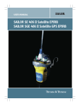
1
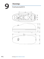
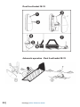
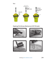
EP70/EG70
User Guide
ENGLISH
| www.simrad-yachting.com
Preface
As Navico is continuously improving this product, we retain theright
to make changes to the product at any time which may not be
reflected in this version of the manual. Please contact your nearest
distributor if you require any further assistance.
It is the owner’s sole responsibility to install and use the equipment
in a manner that will not cause accidents, personal injury or
property damage. The user of this product is solely responsible for
observing safe boating practices.
NAVICO HOLDING AS AND ITS SUBSIDIARIES, BRANCHES AND
AFFILIATES DISCLAIM ALL LIABILITY FOR ANY USE OF THIS PRODUCT
IN A WAY THAT MAY CAUSE ACCIDENTS, DAMAGE OR THAT MAY
VIOLATE THE LAW.
Governing Language: This statement, any instruction manuals,
user guides and other information relating to the product
(Documentation) may be translated to, or has been translated from,
another language (Translation). In the event of any conflict between
any Translation of the Documentation, the English language
version of the Documentation will be the official version of the
Documentation.
This manual represents the product as at the time of printing.
Navico Holding AS and its subsidiaries, branches and affiliates
reserve the right to make changes to specifications without notice.
Copyright
Copyright © 2012 Navico Holding AS.
Warranty
The warranty card is supplied as a separate document.
In case of any queries, refer to the brand web site of your display or
system:
pro.simrad-yachting.com
www.simrad-yachting.com
Preface | EP70 / EG70 User Guide
|1
The chapter covering battery replacement is added for information
only. Simrad does not take any responsibility for improper
disassembling/assembling of the beacon. We strongly recommend
all service to be done by authorized Simrad agents. In addition
to normal service, Simrad agents have the necessary equipment
and education to test the operational functions of the beacon.
Non-original maintenance and/or service parts may destroy the
equipment function and performance.
Product Safety Data Sheet
PRODUCT NAME:
TYPE NO.:
TRADE NAMES:
APPROXIMATE WEIGHT:
CHEMICAL SYSTEM:
DESIGNED FOR RECHARGE:
Energizer Battery
L91 Volts: 1.5
ULTIMATE (L91)
14.5 g.
Lithium Iron Disulfide
No
Hazards Identification
Under normal conditions of use, the battery is hermetically sealed.
Ingestion: Swallowing a battery can be harmful.
Inhalation: Contents of an open battery can cause respiratory
irritation.
Skin Contact: Contents of an open battery can cause skin irritation.
Eye Contact: Contents of an open battery can cause severe irritation.
First Aid Measures
Ingestion: Do not induce vomiting or give food or drink. Seek
medical attention immediately. CALL NATIONAL BATTERY
INGESTION HOTLINE for advice and follow-up (202-625-3333) collect
day or night.
Inhalation: Provide fresh air and seek medical attention.
Skin Contact: Remove contaminated clothing and wash skin with
soap and water.
Eye Contact: Immediately flush eyes thoroughly with water for at
least 15 minutes, lifting upper and lower lids, until no evidence of
the chemical remains. Seek medical attention.
2|
Product Safety Data Sheet | EP70 / EG70 User Guide
Note: Carbon black is listed as a possible carcinogen by International
Agency for Research on Cancer (IARC).
Fire Fighting Measures
In case of fire where lithium batteries are present, flood area with
water or smother with a Class D fire extinguishant appropriate for
lithium metal, such as Lith-X. Water may not extinguish burning
batteries but will cool the adjacent batteries and control the spread
of fire. Burning batteries will burn themselves out. Virtually all fires
involving lithium batteries can be controlled by flooding with
water. However, the contents of the battery will react with water
and form hydrogen gas. In a confined space, hydrogen gas can
form an explosive mixture. In this situation, smothering agents are
recommended. A smothering agent will extinguish burning lithium
batteries.
Emergency Responders should wear self-contained breathing
apparatus. Burning lithium-iron disulfide batteries produce toxic and
corrosive lithium hydroxide fumes and sulfur dioxide gas.
Handling And Storage
Storage: Store in a cool, well ventilated area. Elevated temperatures
can result in shortened battery life. In locations that handle large
quantities of lithium batteries, such as warehouses, lithium batteries
should be isolated from unnecessary combustibles.
Mechanical Containment: If potting or sealing the battery in an
airtight or watertight container is required, consult your Energizer
Battery Manufacturing, Inc. representative for precautionary
suggestions. Do not obstruct safety release vents on batteries.
Encapsulation of batteries will not allow cell venting and can cause
high pressure rupture.
Handling: Accidental short circuit for a few seconds will not seriously
affect the battery. Prolonged short circuit will cause the battery
to lose energy, generate significant heat and can cause the safety
release vent to open. Sources of short circuits include jumbled
batteries in bulk containers, metal jewelry, metal covered tables or
metal belts used for assembly of batteries into devices. Damaging a
lithium battery may result in an internal short circuit.
• The contents of an open battery, including a vented battery, when exposed to water, may result in a fire and/or explosion. Crushed or damaged batteries may result in a fire.
• If soldering or welding to the battery is required, consult your Product Safety Data Sheet | EP70 / EG70 User Guide
|3
Energizer representative for proper precautions to prevent seal damage or short circuit.
Charging: This battery is manufactured in a charged state. It is not
designed for recharging. Recharging can cause battery leakage or, in
some cases, high pressure rupture. Inadvertent charging can occur if
a battery is installed backwards.
Labeling: If the Energizer label or package warnings are not visible, it
is important to provide a package and/or device label stating:
WARNING
Battery can explode or leak and cause burns if installed backwards,
disassembled, charged, or exposed to water, fire or high
temperature. Where accidental ingestion of small batteries is
possible, the label should include:
WARNING
(1) Keep away from small children. If swallowed, promptly see
doctor. Battery can explode or leak and cause burns if installed
backwards, disassembled, charged, or exposed to water, fire or high
temperature.
TEST AND MAINTENANCE RECORD
DATE
N/T/BSIGNINSP
N= New EPIRB installed, T= Test, B= New battery
Test Of Radio Equipment
Monthly:
Float-free and manual EPIRBs to be checked using the means
provided for testing on the equipment. Check data for periodical
maintenance requirement for float-free EPIRB.
False alerts transmitted by EPIRB
False alerts are a serious problem for the rescue service. Nearly 90%
of EPIRB initiated distress alerts turn out to be false alarms.
4|
Product Safety Data Sheet | EP70 / EG70 User Guide
If for any reason, your EPIRB should cause a false alarm, it is most
important that you contact the nearest search and rescue authority
and tell them it was a false alarm. They can then stand down any
rescue service (coast radio station or appropriate CES or RCC). Use
any means at your disposal to make contact. Switch off the distress
alarm by de-activating your EPIRB, as soon as possible.
If your beacon is activated in a non-distress situation or a distress
situation which has been resolved and you no longer require
assistance, contact the nearest search and rescue authorities via the
most expeditious means available with the following information:
•
•
•
•
•
•
•
•
Beacon ID number (15 character UIN):
Position (At time of activation):
Date of Activation:
Time of Activation (Time zone):
Duration of Activation:
Beacon marke and model:
Vessel Name/lD:
Circumstances/cause (if known):
USA
The United States search and rescue authority is the U.S. Coast
Guard. The primary points of contact are:
Pacific Ocean Area
USCG Pacific Area Command Centre
Tel: +1 (510)-437-3701
Atlantic Ocean / Gulf of Mexico Area
USCG Atlantic Area Command Centre
Tel: +1 (757)-398-6231
From Any Location
USCG Headquarters Command Centre
Tel: +1 (800)-323-7233
Product Safety Data Sheet | EP70 / EG70 User Guide
|5
Contents
8
General Description
8EP70/EG70
9
System Description
9
Signal Detection
10 Distress Location Determination
10 EPIRB Registration
12
EPIRB Description
12General
12 Main Module With Antenna
12 Battery Module
13Installation
13Brackets
13 Float Free Bracket FB-70
14 Manual Bracket MB-70
14 Mounting The FB-70/MB-70 Brackets
15
Operation Instructions
15
Manual Operation
18
Periodical Control
19Maintenance
19
19
19
Epirb Module / Battery Module
Change Of Battery
Hydrostatic Release Replacement
20
Technical Specifications
22
Spare Parts
23Drawings
6|
Contents | EP70 / EG70 User Guide
1
General Description
The EP70/EG70 is emergency equipment consisting of:
• EP70/EG70 Cospas-Sarsat emergency EPIRB
• One of the following brackets:
• FB-70 - Automatic float free bracket.
• MB-70 - Manual bracket.
The EP70/EG70 EPIRB is developed to meet the regulations and
rules for use on vessels and life rafts in the maritime service. EP70/
EG70 meets the following specifications for 406 MHz EPIRBs for use
in search and rescue operations at sea.
See “Declaration of Conformity” document at www.pro.simradyachting.com for information of required standards.
EP70/EG70
The EP70/EG70 is buoyant, and is designed to automatically release
and activate in case of an emergency where the EPIRB and its
bracket is submerged into the sea. The EP70/EG70 can also be
operated as a manual EPIRB, by manually releasing it from its bracket
and then activating it.
Two different brackets are currently available for the EP70/EG70. MB70 is the manual bracket and FB-70 is the automatic bracket with
cover. The manual bracket comes without the hydrostatic release
mechanism and is used to store the beacon inside the wheelhouse
or other protected places. The automatic bracket is mounted in a
free space outside where the beacon can be released automatically.
The purpose of the EP70/EG70 is to give a primary alarm to the
search and rescue authorities. The EPIRB gives an immediate alarm
when activated, transmitting the ID of the ship in distress. Care must
be taken not to activate the EPIRB unless in an emergency situation,
in such cases the user will be held responsible. For periodic testing
a test function is implemented. During the test cycle the EPIRB
does a self-test on the transmitters and on the battery status. No
emergency signal is transmitted during the self-test.
The battery of the EPIRB will last for at least 48 hours from activation
of the EPIRB.
General Description | EP70 / EG70 User Guide
|7
System Description
The Cospas-Sarsat system was introduced in 1982 as a worldwide
search and rescue system with the help of satellites covering the
earth’s surface. Since the introduction of the system more than
28000 persons have been rescued by the Cospas-Sarsat system
(2009). Currently the system consists of 5 functional satellites in
a polar orbit constellation, these satellites cover the entire earth’s
surface and receive the emergency signal from the 406 MHz
transmitter within the EP70/EG70, more polar orbiting satellites will
be available in the future, giving a faster location and rescue time.
In addition several geostationary satellites are equipped with a 406
MHz transponder, these satellites are not able to locate the EP70/
EG70 but will give an early warning to the rescue forces, minimising
the time from an emergency occurs till the rescue forces are at the
site.
Each emergency EPIRB in the system is programmed with its own
unique code, therefore it is vital that the ships data that is given
to the dealer you obtained your EP70/EG70, is correct. It is also
important that your EPIRB is registered in the database for each
country. This database is normally located in the same country that
the ship is registered.
Signal
Detection
When the EP70/EG70
is activated (manually
or automatically)
it transmits on the
frequencies 121.5
MHz and 406.037
MHz. An analogue
signal is emitted on
121.5 MHz and a
digital signal is transmitted on 406.037 MHz. After the EP70/EG70 is
activated, the next passing satellite will detect the transmitted signal
and relay it to an antenna at a ground station, called LUT.
The International Cospas-Sarsat System has ceased satellite
processing of 121.5/243 MHz beacons from 1 February 2009.
8|
General Description | EP70 / EG70 User Guide
Distress Location
Determination
The location of the distress signal is
determined by taking measurements of the
doppler shift of the EPIRB frequency when
the satellite first approach and then pass the
EPIRB.
The actual frequency is heard at the time of
closest approach (TCA). Knowing the position
of the satellite and using the received
doppler signal information, it is possible to
determine the location of the EP70/EG70 from the satellite at the
TCA. At the LUT, actually two positions are calculated. One is the
actual position (A) and the other is the mirror image (B) position.
A second satellite pass confirms the correct location (A). Doppleronly accuracy is within 5 km (3 mi) (3.1 statute miles or 2.6 nautical
miles)— that is, the position is sufficiently accurate for SAR purposes
even after only one pass. What’s more, the most likely of the two
’mirror’ positions can be determined valid with 98.5% accuracy after
only one satellite pass. This accuracy can be increased to 99.3%
using so-called ”combined Leo-Geo processing,” and this technique
also enables accurate positions to be generated with as little as
two or three bursts from the beacon (i.e. less than 4 minutes of
transmission) and thus greatly increases the chances of being found
even if the beacon is ultimately consumed by fire or is otherwise
destroyed
EPIRB Registration
Normally the MCC will contact the vessel or the contact person
registered in a shipping register and/or an EPIRB register (Ships
owner, family member etc.) before alerting the RCC. This is to
determine if the alarm from the EPIRB for some reason is a false
alarm, and an expensive rescue operation can be avoided. Because
of this it is important that the ships data is correct in the shipping
register or in the EPIRB database.
You should register your beacon with the national authority
associated with the country code in the hexadecimal identification
(15 Hex ID) of your beacon. You can register your beacon online
with the Cospas-Sarsat IBRD if your country does not provide a
registration facility and your country has allowed direct registration
in the IBRD: www.406registration.com
General Description | EP70 / EG70 User Guide
|9
If your country operates a national beacon registry, consult
the document C/S S.007 ”Cospas-Sarsat Handbook of Beacon
Regulations” available at www.cospas-sarsat.org to obtain the point
of contact.
Some EPIRB registration links:
USA: http://www.beaconregistration.noaa.gov
UK: http://www.mcga.gov.uk (search for ”EPIRB registration”)
USA
USA REGISTRATION CARD
For registration of the beacon, use this link:
http://www.beaconregistration.noaa.gov
Follow instructions you see on your screen.
Other registrations methods are mail or fax. Forms are ready with
correct information and it may be downloaded from the above web
site.
The Emergency Contact information has to be accurate, especially
regarding the telephone number, as this will be used to validate
an alert. Only if the beacon registration and approximate location
details can be confirmed will USCG (United States Coast Guard)
launch an immediate rescue, otherwise there will be a delay whilst
further alerts from the same source are received and verified.
Registration address:
NOAA/SARSAT Beacon Registration
E/SP3
Federal Building 4, Room 3320
5200 Auth Road, Suitland
MD 20746–4304
10 |
General Description | EP70 / EG70 User Guide
2
EPIRB Description
General
The EP70/EG70 consists of upper and lower house mounted
together withan equator ring with gasket. EP70/EG70 consists of the
following main parts:
• Main module with antenna
• Battery module
Main Module With Antenna
The EPIRB module consists of:
• The main board including all electronic circuitry and the main switch
• Antenna with flash LED
Battery Module
The Battery module supplies the EPIRB module with 12 V power to
keep the EPIRB transmitters active for 48 hours when activated, and
for test sequences. The battery pack is attached inside the lower
house.
The seawater contacts are mounted in the battery module. The
batteries are mounted in a plastic battery holder.
EPIRB Description | EP70 / EG70 User Guide
| 11
3
Installation
Brackets
Two different brackets are currently available for the EP70/EG70.
Float Free Bracket FB-70
WARNING:
DO NOT INSTALL THE EPIRB NEAR STRONG
MAGNETIC FIELDS THAT COULD ACTIVATE THE BEACON
When the EP70/EG70 is mounted in the float-free bracket, FB70, it will operate as an automatic float free unit. The satellite
float-free EPIRB should be located/installed so that the following
requirements are fulfilled:
• The EPIRB should, with greatest possible probability, float-free and avoidbeing caught in railings, superstructure, etc., if the ship sinks.
•
The EPIRB should be located so that it may be easily released manually and brought to the survival craft by one person. It should therefore not be located in a radar mast or any other places which can only be reached by vertical ladder.
The location should be well protected from environmental
conditions such as direct sea-spray, chemicals, oil, exhaust and
vibrations.
See drawing on page 23
12 |
Installation | EP70 / EG70 User Guide
Manual Bracket MB-70
When the EP70/EG70 is mounted in the MB-70 bracket, it will
operate as a manual unit. This bracket is typically used to store the
EPIRB inside the wheelhouse or other protected areas of the ship.
When the EP70/EG70 is mounted in the MB-70 bracket, the EPIRB
can be activated as described in 5.1.1, but the sea water contacts are
deactivated in the bracket. The bracket should be mounted in an
easily accessible place where it can be removed in a hurry in case of
an emergency.
See drawing on page 24.
Mounting The FB-70/MB-70 Brackets
The bracket is mounted with 5mm bolts according to the drawing.
Use the bolts supplied with the bracket. The bracket could be
mounted in either a vertical or horizontal position, whichever is the
best regarding maintenance and operation. A vertical position is
recommended.
Installation | EP70 / EG70 User Guide
| 13
4
Operation Instructions
Warning
• USE ONLY DURING SITUATIONS OF GRAVE AND IMMINENT DANGER
• REPLACE THE BATTERY AFTER THE SATELLITE EPIRB IS OPERATED FOR ANY PURPOSE OTHER THAN A TEST
The EP70/EG70 is designed to be operated either manually or
automatically. The EPIRB is always armed, that is the EPIRB will
automatically start to transmit when the EPIRB is out of the bracket
and deployed into water. In the EPIRB there is an automatic safety
switch. This switch prevents the seawater contacts from operating
the EPIRB (caused by ice, sea-spray etc.) as long as the EPIRB is
placed in its bracket.
Manual Operation
Out Of Bracket
See drawing on page 24 and follow instructionsfrom 4-5 on page
18.
Float Free Bracket FB-70
See drawing on page 25. For operation of the beacon in the bracket
please follow instructions 1 to 7.
It is not recommended to operate the beacon inside a life raft or
under a cover or canopy. Do NOT tie the lanyard to the ship in
distress, as this will prevent the unit to functioning if the ship sinks.
1.
2.
3.
4.
5.
6.
7.
14 |
Remove the locking pin from the bracket (FB-70)
Remove the FB-70 cover
Take out the EPIRB from the bracket
Pull the locking pin holding the main switch.
Move main switch to the left, to ON position. The LED indicator, located at the top of the antenna, will start to flash, indicating that the EPIRB is operating.
Tie the beacon lanyard to you or to the survival craft
If possible keep the EPIRB in an open area, away from any metal objects (ship construction etc.) that may limit the satellite coverage. This is especially important for EP70/EG70, since it needs good reception to obtain a GPS position.
Operation Instructions | EP70 / EG70 User Guide
NOTE:
To stop transmission, move the main switch to READY position.
AUTOMATIC OPERATION - FLOAT FREE BRACKET FB-70
See drawing on page 25.
1. 2. The EP70/EG70 will automatically release from the bracket, float to the surface and start to transmit when the EPIRB, in its bracket is deployed into water at a depth of app. 2-4 meters (6 - 13 feet).
Transmission will continue until the EPIRB is lifted out of the water, and dried off. The transmission can also be stopped by placing the EPIRB in the bracket.
Test
To perform the self-test, the EPIRB has to be removed from the
bracket. FB-70 bracket: Release FB-70 top cover by removing the
locking pin.
See drawing on page 26.
1.
2. 3. Push and hold switch in TEST position for 15 seconds. Keep hands and other objects away from the antenna.
Test passed after one single flash only!
Release the switch and put the EPIRB back into the bracket
Warning
The EPIRB can drop out of the FB-70 bracket when releasing top
cover
GPS Test:
NOTE:
Limit this test to max. once/month as this test will reduce lifetime of
EPIRB battery! The EP70/EG70 has maximum 60 GPS TESTs that can
be performed during battery lifetime.
1. Move Switch to TEST twice within 3 seconds and release
2. EPIRB will BEEP shortly every 3 seconds until GPS position acquired
3. OK = 2 BEEPS (see below description if Not OK)
4. Normal SELFTEST is performed after GPS TEST and position transmitted on 406.037 MHz. GPS position may be received on an EPIRB Tester for verification
Operation Instructions | EP70 / EG70 User Guide
| 15
There are two possible error conditions during this test:
a) 5 BEEPS = Did not acquire GPS position
b) 10 -” - = Number of GPS TEST above limit (>60)
EPIRB Error Messages
If the self test detects a fault in the EPIRB module, one or more of
the following indications are shown:
16 |
Number
of flashes:
Fault indication:
1
2
3
4
5
6
7
NONE
Low power on 406 MHz transmitter
Low battery voltage
Low power on 121.5 MHz transmitter
PLL on 406 MHz transmitter out of lock
PLL on 121.5 MHz transmitter out of lock
EPIRB module not programmed or programming not complete
Operation Instructions | EP70 / EG70 User Guide
5
Periodical Control
Every Month:
Perform EPIRB self-test.
What the self-test actually does is to send out a short test signal on
121,5 and 406,037MHz, testing the output of the transmitter. While
transmitting the test signal, the battery voltage, output power and
phase lock is tested.
During the test of the 406MHz transmitter a test message
is transmitted, this test message is coded with a special
synchronization code and will not be recognized as real alert by the
Cospas-Sarsat satellites. Carry out visual inspection for defects on
both the EP70/EG70 and Bracket. The EP70/EG70 should be easily
removed and replaced in the Bracket. Make sure that the EP70/EG70
and Bracket is not painted or otherwise covered with chemicals, oil,
etc.
Check the expiry date of the EPIRB Battery and the Hydrostatic
Release Mechanism. Check the presence of a firmly attached lanyard
in good condition and that it is neatly stowed and is not tied to the
vessel or the mounting bracket. If the EP70/EG70 is the main EPIRB
on board, these rules must be followed:
Every 12th month:
If the EP70/EG70 is the main EPIRB on board and the ship falls under
national regulation and/or the SOLAS regulations of SBM, these
rules must be followed: Perform extended annual test according
to IMO’s MSC/Circ.1040 (Annual testing of 406 MHz satellite EPIRBs)
as required by SOLAS IV/15.9.This test can be carried out by one of
Navico´s authorized representatives or any other service provider in
possession of a Cospas/Sarsat EPIRB tester/decoder.
Every 2ndYear:
Hydrostatic Release Mechanism including Plastic Bolt on the Float
Free Brackets must be replaced. (Check expiry date on label).
Every 5thYear:
• Battery change
• SBM (see page 19)
Periodical Control | EP70 / EG70 User Guide
| 17
6
Maintenance
Epirb Module / Battery Module
If the EPIRB is fitted on a vessel which requires GMDSS compliant
equipment, the EPIRB shall be tested and approved as required
by SOLAS regulation IV/15.9.2 of SOLAS 1974 as amended with,
in accordance with MSC/Circ.1039 guidelines for shore-based
maintenance of Satellite EPIRBs within 5 years, or by the date of
battery expiry, whichever comes first.
Change Of Battery
The EP70/EG70 battery must be changed at Simrad SBM authorized
workshop to be GMDSS compliant. If your EP70/EG70 is not under
any international or national regulations, battery can be change by
authorized Simrad representatives/partners/dealers.
Hydrostatic Release Replacement
Warning
Only Simrad approved hydrostatic release is acceptable for use
Replacing The Release Mechanism In FB-70 Bracket
See drawing on page 26.
1. Release and remove FB-70 top cover by removing the locking split pin (1). WARNING! The EPIRB can drop out of the FB-70 bracket when releasing the top cover. Remove the EPIRB from the bracket.
2. Press down the spring-loaded bracket plate and remove the hydrostatic unit by sliding it out of its locking slot. See arrow for direction.(2).
3. Check the expiry date of the new hydrostatic release mechanism (3). The date should be approximately two years from the date of purchase.
4. Install a new hydrostatic unit by pressing down the spring loaded bracket plate and sliding the unit into its locking slot (4).
5. Refit the EPIRB and the FB-70 top cover. Be sure that the top cover is locked at the bottom end and that the top end are
fixed at hydrostatic release mechanism rod. Replace The locking split pin (1)
18 |
Maintenance | EP70 / EG70 User Guide
7
Technical Specifications
GENERAL
Battery:
Housing:
Dimensions:
• Height: • Max diameter: • Weight:
Materials:
Compass safe dist.:
Temp. operating:
Temp. storage:
Operating life:
Lithium/iron disulfide, 12V/2900 mAh,
5 years service life
Glass reinforced Polycarbonate
340 mm
128mm
680 gram
Polycarbonate
0,85 m
-20°C to + 55°C
-40°C to + 65°C
Minimum 48 hours at -20°C
COSPAS-SARSAT TRANSMITTER
Frequency:
Output power:
Protocols:
Modulation:
Data encoding:
Stability: Type Approval Cert.:
406.037 MHz ±2 ppm
5W ±2 dB
EP70/EG70: Maritime, Serialized, Radio Call sign, Location protocols
Phase modulation 1.1 ±0.1 rad
Bi Phase L
Short term: ≤ 2 x10e-9
Medium term: ≤ 10e-9
Residual noise: ≤ 3 x10e-9
Bit rate: 400 b/s
Antenna: Omni directional
TAC-222
NAVIGATION DEVICE
Type: Antenna:
22 Channel GPS Receiver
Chip type
HOMING TRANSMITTER
Frequency:
Output power:
Modulation:
Stability: Antenna: 121.500 MHz
Up to 100 mW
A9, AM sweep tone between 300Hz and 1600Hz
Sweep range: 700 Hz
Sweep rate: 2.5 Hz
10 ppm over temperature range
Omni directional
Technical Specifications | EP70 / EG70 User Guide
| 19
BRACKETS
Float Free Bracket FB-70
See drawing on page 27.
Materials:
Dimensions (hwd): Weight: Release mechanism: Luran S/ ABS
(385 x 151 x 148) cm
850 g
HRU kit
Manual Bracket MB-70
See drawing on page 27.
Materials:
Dimensions (hwd):
Weight: 20 |
PA6 + 30% fibre glas (Polyamide)
(156x 134 x 98.5) cm
150 g
Technical Specifications | EP70 / EG70 User Guide
8
Spare Parts
Battery kit, EP70/EG70/EP70/EG70 Hydrostat kit FB-70 MB-70 - part no. 000-10736-001
- part no. 000-10737-001
- part no. 000-10734-001
- part no. 000-10735-001
NOTE:
Keep the original satellite EPIRB packaging, since it may be needed
if the EPIRB has to be shipped for servicing. UN requirements
for shipping some batteries as hazardous goods require certain
packaging standards and labelling
Spare Parts | EP70 / EG70 User Guide
| 21
9
22 |
Drawings
Float free bracket FB-70
Drawings | EP70 / EG70 User Guide
Manual Bracket MB-70
M5 bolts x 3
Manual Operation - Out Of Bracket
1
2
Drawings | EP70 / EG70 User Guide
3
| 23
Float Free Bracket FB-70
Automatic operation - Float free Bracket FB-70
24 |
Drawings | EP70 / EG70 User Guide
Test
Only 1
flash = OK
Release
the switch
after 15
sec.
Hold 15
sec.
1
2
3
Replacing The Release Mechanism In FB-70 Bracket
1
2
3
4
Drawings | EP70 / EG70 User Guide
| 25
Float Free Bracket FB-70
Manual Bracket MB-70
26 |
Drawings | EP70 / EG70 User Guide
*000-10741-001*
www.simrad-yachting.com
N2584