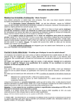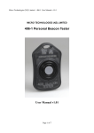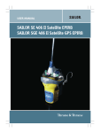
1
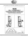
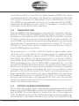
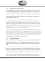
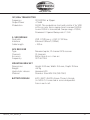
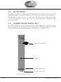
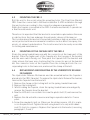
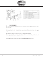
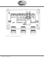
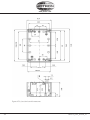
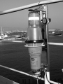
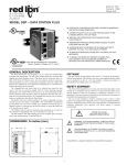
USERS MANUAL
Tron S-VDR CAPSULE
www.jotron.com
www.jotron.com
EC Declaration of Conformity, available at www.jotron.com
2
82310_UM_SVDR_H
www.jotron.com
Amendment Records
AMEND- INCORP. DATE
PAGE(S)
VERSION
MENT NO. BY
REASON FOR CHANGE
1
ES
14.02.06
44 pages
A
Kontroll med dokumenter.doc
2
ES
21.03.06
37
B
Ch. 6.1 - Self-test
3
ES
13.11.06
28
C
IP info
4
ES
18.04.07
Total: 44
D
New company name
5
ES
01.10.07
28,29,33,37,38
E
Changed text and fuses
6
ES
22.02.08
2,3,4,5,36,41
F
Inserted text
7
ES
18.12.08
21
G
Additional 4GB flash drive
8
TH
11.06.09
All pages
9
H
Layout changes
10
11
12
13
14
15
16
17
82310_UM_SVDR_H
3
www.jotron.com
IMPORTANT
TO PERMANENTLY DISABLE EPIRB
The battery module must be removed and treated according to
chapter 5.6.2 in this manual.
WARNING
USE ONLY THIS EPIRB DURING SITUATIONS
OF GRAVE AND IMMINENT DANGER
FALSE ALERTS
De-alerting sar forces in event of inadvertent activation, or assistance no longer required
False alarms divert rescue forces from real distress situations.
Intentional false alerts may result in penalties.
Responding to false alarms costs millions annually.
WE NEED YOUR HELP:
1. Remember: activating your beacon is the equivalent of trans- mitting a mayday.
2. Follow manufacturer procedures when testing your beacon.
3. If your beacon is activated
• In a non-distress situation, or
• In a distress situation, which resolves, and you no longer require assistance;
Contact the nearest sar authorities via the most expedetious
means available with the following information:
4
82310_UM_SVDR_H
www.jotron.com
Beacon ID number (15 character UIN):
Position (at time of activation):
Date of Activation:
Time of Activation (Time zone):
Duration of Activation:
Beacon make and model:
Vessel Name/ID:
Circumstances/cause (if known):
PRIMARY U.S. POINT OF CONTACT IS THE U.S. COAST
GUARD: PASS BY MOST EXPEDITIOUS, DIRECT MEANS TO
FOR THE PACIFIC:
Pacific area command center (510) 437 3700
FOR THE ATLANTIC/GULF OF MEXICO/ATLANTIC:
Atlantic area command center (757) 398-6390
OR FROM ANY LOCATION: 82310_UM_SVDR_H
(800) 323 SAFE
(800) 323 7233
5
www.jotron.com
The information in this book has been carefully checked and is believed to
be accurate. However, no responsibility is assumed for inaccuracies.
CAUTION!
This equipment contains CMOS integrated circuits. Observe handling precautions to avoid static discharges which may damage these devices.
Jotron AS reserves the right to make changes without further notice to any
products or modules described herein to improve reliability, function or design. Jotron AS does not assume any liability arising out of the application
or use of the described product.
WARNING / IMPORTANT
Jotron AS is a prime manufacturer of safety equipment designed for rescue
of human lives and their property. For safety equipment to be effective in
line with the design parameters it is important that they are handled, stowed
and maintained in compliance with the manufacturers instructions. Jotron
AS Cannot be held responsible for any damage caused due to incorrect use
of the equipment or breach of laid down procedures or for failure of any
specific component or other parts of the equipment.
Jotron AS does not take any responsibility for improper disassembling/
assembling of the equipment. We strongly recommend all service to be
done by authorized Jotron agents. In addition to normal service, Jotron AS
agents have the necessary equipment and education to test the operational functions of the beacon.
6
82310_UM_SVDR_H
www.jotron.com
WARRANTY
All goods sold by Jotron AS are warranted to be free from defect in workmanship and material for the period of five (5) years from the date of delivery (unless stated otherwise and confirmed in writings).
PROVIDED:
(a) Jotron AS is given full particulars in writing of any claim prior to the expiration of such a period and within fourteen days of the dis
covery of the alleged defect.
(b)
The goods have stored, installed, maintained and used properly having regard in particular to Jotron AS specifications.
(c)
Liability shall be limited at Jotron AS options to replacement or re
pair or to a sum not exceeding the net invoice value of the defec
tive goods.
(d)
Upon request the alleged faulty goods are returned to Jotron AS at the Buyer’s expense.
(e)
Unless expressly stipulated in the acceptance of the order Jotron AS gives no warranty or guarantee of the fitness or suitability of the goods for any purpose whether disclosed or otherwise.
(f)
All other warranties or conditions expressed or implied are hereby excluded and Jotron AS shall in no circumstances be liable for con
sequential damages.
82310_UM_SVDR_H
7
www.jotron.com
Abbreviations and definitions
BAUD
Transmission rate unit of measurement for binary coded data (bit per second).
BIT
Short form of Binary Digit. The smallest element of data in a binary-coded
value.
BITE
Built in test equipment
BPS
Bits Per Second.
CHARACTER STRING
Continuous characters (other than spaces) in a message.
CHECKSUM
The value sent with a binary-coded message to be checked at the receiving
end to verify the integrity of the message.
COSPAS
COsmicheskaya Sistyema Poiska Avariynich Sudov (Space System for the
Search of Vessels in Distress)
CLOCK
A precisely spaced, stable train of pulses generated within an electronic system to synchronize the timing of digital operations within the system.
DEFAULT
The operator initiates a condition that the navigator assumes automatically if
no other condition.
EPIRB
Emergency Position Indicating Radio Beacon
8
82310_UM_SVDR_H
www.jotron.com
FRM
Final Recording Medium
GLOBAL POSITIONING SYSTEM (GPS)
The NAVSTAR Global Positioning System, which consists of orbiting satellites, a
network of ground control stations, and user positioning and navigation equipment. The system has 24 satellites plus 3 active spare satellites in six orbital
planes about 20,200 kilometers above the earth.
GPS
Global Position System
GPS SYSTEM TIME
Time corrected to Universal Time Coordinated (UTC) and used as the time
standard by the user segment of the GPS system.
IEC
International Electro-technical Commission
IMO
International Maritime Organization
INTERFACE
Electronic circuits that permit the passage of data between different types
of devices; For example, the speed and heading interface circuit permits data
from a speed log and compass to pass to the navigator processor.
ITU
International Telecommunication Union
LED
Light Emitting Diode
LUT
Local User Terminal (Ground Station)
MCC
Mission Control Centre
82310_UM_SVDR_H
9
www.jotron.com
PROCESSOR
The processor circuit card in the console that controls system operations and
computes the positioning/navigation solutions.
RCC
Rescue Coordination Centre
SARSAT
Search and Rescue Satellite-Aided Tracking System
SBM
Shore Based Maintenance – as required by SOLAS regulation IV/15.9.2 of
SOLAS 1974 as amended with, in accordance with MSC/Circ. 1039 guidelines
for Shore-Based Maintenance (SBM) of Satellite EPIRBs within 5 years if:
Passenger ships (> 12 passengers) and cargo ships (> 300GT) engaged in International voyages, shall perform SBM as follows:
• Latest by the date of the EPIRB label with this text, or the battery
Label, whichever is first.
• When this EPIRB becomes due for SBM in accordance with national
requirements.
SOFTWARE
Values programmed and preloaded into memory. The values represent a permanent set of instructions for running the automatic functions (computations)
of the navigator.
S-VDR
Simplified Voyage Data Recorder
VHF
Very High Frequency -A set of frequencies in the MHz region
VSWR
Voltage standing wave ratio
10
82310_UM_SVDR_H
www.jotron.com
82310_UM_SVDR_H
11
www.jotron.com
Table of contents
1
General Description
1.1
Epirb Module
1.1.1
System Description
1.1.2
Signal Detection
1.1.3
Distress Location Determination
1.1.4
Added Value In The Epirb
1.1.5
Epirb Registration
1.2
S-VDR Server Module
14
14
14
15
15
17
17
18
Technical Specification
20
2
3
Functional Description
3.1
General
3.1.1
Capsule Housing
3.1.2
S-VDR Server Module
3.1.3
Epirb Module
3.1.4
Battery Module
3.1.5
Automatic Release Bracket, FBR-3
3.1.6 S-VDR Data And Power Connections
3.1.6.1 S-VDR Data And Power
Connector, Capsule
3.1.6.2 S-VDR Data And Power Connector,
Bracket
3.1.7
Wiring Table S-VDR Data And Power
Connection
22
22
23
23
23
24
24
25
4
Installation
4.1
Mounting Bracket FBR-3
4.2
Mounting The FBR-3
4.3
Mounting Of The Capsule Into The FBR-3
4.4
Replacement And Mounting Of The Hydrostatic
Release Mechanism
4.5
Junction Box
28
28
29
29
12
25
26
26
29
30
82310_UM_SVDR_H
www.jotron.com
5
Operating Instructions
5.1
FBR-3 Float Free Bracket
5.2
Manual Operation Of Epirb Module
5.3
Automatic Operation Of Epirb Module
5.4
Testing The Epirb Module
5.5
Operation Of The S-VDR Module
5.5.1
Operating Software
5.6
Change Of Battery
5.6.1 Msc Circ. 1039
5.6.2 Battery Disposal
5.6.2.1 Incineration
5.6.2.2 Land Filling
5.6.2.3 Recycling
34
34
34
35
35
36
36
36
36
37
37
37
37
6
Maintenance And Troubleshooting
6.1
Epirb Module / Battery Module
6.2
Testing Epirb Module
6.2.1 Self-Test With Sea Water Contacts
Activated
6.2.2 Self-Test With Sea Water Contacts
Deactivated
6.3
Maintenance Of Epirb
6.3.1 Epirb Module Error Messages
6.4
Test Of GPS Receiver Without Transmitters
Activated
6.5
S-VDR Module
38
38
38
Service Agents
42
7
82310_UM_SVDR_H
38
38
39
40
41
41
13
www.jotron.com
1
GENERAL DESCRIPTION
The Main parts of the Capsule (Tron S-VDR CAPSULE) are the EPIRB (EPIRB
module) and the S-VDR Server module. The Capsule is developed to meet the
regulations and rules for use on ships, vessels and life rafts in the maritime service. The Capsule meets the following specifications for S-VDR and 406MHz
EPIRB for use in search and rescue operations at sea:
• IEC 61996 ed.2
• IEC 61097-2 ed.3.0 (2008)
• IEC 60945 ed.4.0 (2002)
• C/S T.001 and C/S T007 (Nov. 2007)
• IMO MSC.163 (78)
• IMO A.810 (19)
• MED 96/98/EC
1.1
EPIRB MODULE
The Capsule is buoyant, and is designed to automatically release and to automatically activate the EPIRB in case of an emergency where the Capsule and its
bracket is submerged into the sea. The EPIRB can also be manually operated.
One mounting bracket is available to mount it as an automatic and manual
EPIRB. The purpose of the EPIRB is to give a primary alarm to the search and
rescue authorities. The EPIRB gives an immediate alarm when activated, transmitting the ID of the ship in distress. The EPIRB will at the same time transmit the
position of the ship. Care must be taken not to activate the EPIRB unless in an
emergency situation, in such cases the user will be held responsible. For periodic testing a test function is implemented. During the test cycle the EPIRB does
a self-test off the transmitters and the battery status. No emergency signal is
transmitted during the self-test. The battery of the EPIRB will last for at least
168 hours from activation.
1.1.1
SYSTEM DESCRIPTION
The COSPAS/SARSAT system was introduced in 1982 as a worldwide search and
rescue system with the help of satellites covering the earth’s surface. Since the
introduction of the system more than 11200 persons have been rescued by the
COSPAS/SARSAT system. Currently the system consists of 8 different satellites in a polar orbit Constellation. These satellites cover the entire earth’s surface and receive the emergency signal from the 406MHz transmitter within the
EPIRB. In addition several geostationary satellites are equipped with a 406MHz
transponder. These satellites are not able to locate the Capsule but will give an
early warning to the rescue forces, minimizing the time from an emergency oc
14
82310_UM_SVDR_H
www.jotron.com
curs till the rescue forces are at the site. Each emergency EPIRB in the system
is programmed with its own unique code, therefore it is vital that the ships data
that is given to the dealer you obtained your Tron S-VDR CAPSULE, is correct.
If the EPIRB is programmed with serial protocol, it is important that the EPIRB is
registered in the database for each country. This database is normally located
in the same country that the ship is registered.
1.1.2 SIGNAL DETECTION
When the EPIRB is activated (manually or automatically) it transmits on the frequencies 121.5MHz and 406.028MHz.A homing signal is emitted on 121.5MHz
and a burst is transmitted on 406.028MHz every 50 second after activation.
This burst contains all necessary information about the ships in distress. After the EPIRB is activated, the next passing satellite will detect the transmitted
signal and relay it to an antenna at a ground station, called a LUT (Local User
Terminal). For the 121.5MHz signal the satellite must be within line of sight of
both the EPIRB and a ground station.
The ground station or LUT has a 2500 km satellite reception radius centered at the LUT. In areas without LUT coverage (mostly less populated areas
in the southern hemisphere), signals from the 121.5MHz transmitter will not be
detected by the satellites, only by passing aircraft’s. From the year 2006,no
new satellites will be launched including 121.5MHz receiver, and from the year
2009,satellitedetection of the 121.5MHz EPIRB is terminated. This is not the
case with the 406MHz transmitter, because the satellites have a memory unit,
which stores the signals for relay to the next available LUT giving it a truly global
coverage. Once the signal is received by the LUT, it is processed for location
and sent to a Mission Control Center (MCC).The MCC sorts the alert data according to geographic search and rescue regions and distributes the information
to the appropriate Rescue Co-ordination Center (RCC), or if outside the national search and rescue area, to the appropriate MCC that covers the area that
the distress signal was detected. The RCC in turn takes the necessary action to
initiate search and rescue activities.
1.1.3
DISTRESS LOCATION DETERMINATION
The location of the distress signal is determined by taking measurements of the
doppler shift of the EPIRB frequency when the satellite first approach and then
pass the EPIRB. The actual frequency is heard at the time of closest approach
(TCA). Knowing the position of the satellite and using the received doppler signal information, it is possible to determine the location of the Capsule from the
82310_UM_SVDR_H
15
www.jotron.com
satellite at the TCA. At the LUT, actually two positions are calculated. One is the
actual position (A) and the other is the mirror image (B) position [FIG.1.1.3]. A
second satellite pass confirms the correct location (A).With the 406MHzsystem the real solution can be determined on the first pass with a reliability of
nearly 90% and down to an accuracy of less than 5 km (3.1 miles).
Figure 1.1.3 COSPAS/SARSAT Signal
detection system
16
82310_UM_SVDR_H
www.jotron.com
1.1.4 ADDED VALUE IN THE EPIRB
The EPIRB module has been designed to operate with the COSPAS-SARSAT
system and will enhance further the lifesaving capabilities of conventional
beacons. An integrated 12 channel GPS module accepts continuous positional information from the standard GPS system using 27 satellites providing an
accuracy of approximately 100m.Upon activation of the Capsule in an emergency situation the positional information is incorporated into the distress
message transmitted to LUT.
The main advantage with integrated GPS in the EPIRB is the rapid response
and positional accuracy providing vital information during a rescue operation practically eliminating valuable time spent searching for the distressed.
Whenever a distress message transmitted by the EPIRB is detected by a polar
orbit satellite (LEOSAR) the delayed alert remains the same as for non-GPS
integrated EPIRB`s (max.90 min.), but the position accuracy is improved considerably from a radius of 5 km. to amazing 100m.
Whenever a distress message transmitted by the EPIRB is detected by geostationary satellite (GEOSAR) the alert is immediate (max.5 min.), still providing
the accurate position of 100m. Please note that the positional accuracy delay
is depending on the actual protocol used and programmed into the EPIRB and
the location of the emergency. The information is based on the capacity of
the LEOSAR/GEOSAR COSPAS-SARSAT system.
1.1.5
EPIRB registration
Normally the MCC will contact the vessel or the contact person registered in a
shipping register and/or an EPIRB register (Ships owner, family member etc.)
before alerting the RCC. This is to determine if the alarm from the EPIRB for
some reason is a false alarm, and an expensive rescue operation can be avoided.
Because of this it is important that the ships data is correct in the shipping
register or in the EPIRB database. The Capsule purchased in some countries
will have a registration form attached to it, it is important that this registration
form is completed by the owner and returned to the place the Capsule was
purchased or to the address specified on the registration form.
Other countries use the already available shipping register to obtain the
necessary information for a vessel in distress, in these countries the ship is al82310_UM_SVDR_H
17
www.jotron.com
ready registered and no registration form is necessary, however it is vital that
the coding of the EPIRB is kept up to date with data on the ship (nationality,
call.sign, etc.), to minimize the time from an alarm to the start of the search
and rescue operation.
Reprogramming the EPIRB can be done at authorized Jotron AS agents in
more than 250 different places throughout the world. If you are a resident of
the United States, you must register this beacon with the National Oceanic
and Atmospheric Administration (NOAA) using the registration card included
with the unit. Fill out the form and send it to: SARSAT Beacon Registry, NOAASARSAT, E/SP3, FB4, Room 3320, 5200 Auth Road, Suitland, MD 207464304 Vessel owners shall advise NOAA in writing upon change of vessel or
EPIRB ownership. Transfer of EPIRB to another vessel, or any other change in
registration information, NOAA will provide registrants with proof of registration and change of registration postcards.
1.2
S-VDR SERVER MODULE
The S-VDR Server module consists of S-VDR Server module house including
Flashdisc. The S-VDR Server module is DC powered from the ship via the bracket connector. The S-VDR data is fed from the ships S-VDR system to the
S-VDR Server module through the same connector. When the Capsule leaves
the automatic release bracket, all electrically power and data connections
between the ship S-VDR system and the S-VDR Server module inside the
capsule is broken.
18
82310_UM_SVDR_H
www.jotron.com
82310_UM_SVDR_H
19
www.jotron.com
2
TECHNICAL SPECIFICATIONS
STANDARDS ENVIRONMENTAL
Temperature range
Degree of protection
GENERAL
External Supply voltage
for module
Current consumption
S-VDR Locator lights
Test light
Frequency range Programming
Operating life EPIRB
Dimension
Weight Material housing Antennas 406.028MHz,
121.5MHz
Antenna GPS
IEC 61097-2 ed.2 annex D and EN 60945 ed.4 2002-08
-20°C to +55°C (operating) -40°C to +70°C
(storage)
10 m depth at 5min
12 – 30 VDC
0.25 A at 24VDC
Flashing Xenon light
Test LED
406,028 / 121,5MHz
IR port, 2400 bit/s.
168 hours at -20°C
L = 570 mm Ø = 188 mm.
Approx. 3.5 kg
Polycarbonate with 10% glass fiber.
Built in, vertical polarization, omnidir.
Built in GPS patch antenna.
406MHz TRANSMITTER
Frequency
406.028MHz +2kHz / -5kHz
Output Power
5W ± 2dB
Protocols
MMSI Standard Location (long)
Serial EPIRB Standard (long)
Modulation
Phase modulation 1.1 ±0.1rad.
Data Encoding Bi Phase L.
Stability Short term: ≤ 2*10-9. Medium term: ≤ 2*10-9.
Residual noise: ≤ 3*10-9.
Bit rate 400 b/s
20
82310_UM_SVDR_H
www.jotron.com
121,5MHz TRANSMITTER
Frequency
121.500MHz ± 10ppm.
Output Power
>75mW
Modulation
A9 AM. The modulation starts with a letter V for VDR in Morse code, then a sweep tone from max 1600Hz to min 300Hz is transmitted. Sweep range >700Hz, Downward / Upward Sweep rate 2-3 Hz.
S-VDR MODULE
Flash disk
Interface
Cable length
2GB, 1.7GB free or 4 GB, 3.7 GB free.
Ethernet 10BaseT (10Mbit)
< 100 m
GPS RECEIVER
Type
Channels.
Accuracy
Frequency
Navman Jupiter, 12 channel GPS receiver
12 channels
Better than 4 sec. of an arc.
1575.42 MHz
MOUNTING BRACKET
Dimensions:
Weight: Hydrostatic release
Material Height: 695 mm, Width: 166 mm, Depth: 112mm
4.6 Kg
Hammar H20
Stainless Steel AISI 316 (SIS 2343)
BATTERY MODULE
8 PCs SAFT LSH20 Lithium-Thionyl chloride
(Li-SOCL2). Connected in series and parallel.
Fuse in each cell.
82310_UM_SVDR_H
21
www.jotron.com
3
FUNCTIONAL DESCRIPTION
3.1
GENERAL
The Tron S-VDR Capsule consists of ten parts.
1
2
3
4
5
6
1. Main EPIRB switch
2. Antenna board
3. Upper housing
4. Equator ring with gasket
5. EPIRB module
6. Recovery ring with mounting clips
7. S-VDR Server module
8. Lower housing
9. Battery module
10. S-VDR Connector
7
8
9
10
Figure 3.1, Cut-through S-VDR Capsule
22
82310_UM_SVDR_H
www.jotron.com
3.1.1
CAPSULE HOUSING
The capsule module consists of upper and lower house mounted together with
an equator ring with gasket and locking pin.
3.1.2 S-VDR SERVER MODULE
The S-VDR Server module consists of S-VDR Server module house including
Flash disc and a double-sided PCB board with power regulator and PC circuits.
The S-VDR Server module is DC powered from the ship via the bracket connector. The S-VDR data is fed from the ships S-VDR system to the S-VDR Server
module through the same connector. When the capsule leaves the automatic
release bracket, all electrically power and data connections between the ship
S-VDR system and the S-VDR Server module inside the capsule is broken.
3.1.3 EPIRB MODULE
The EPIRB module consists of four printed circuit boards, which are mounted in
the upper housing:
1. The main board w/GPS patch antenna, Xenon flash and an indicator LED
2. Antenna board. (121.5 / 406 MHz)
3. GPS interface board
4. GPS receiver
For automatic activation of the EPIRB module, put the capsule in the upright
position into the water, and the transmission starts when the seawater completes the circuit between the two external electrodes (sea water contacts).
When the capsule is mounted in the automatic release bracket mechanism,
there is a safety switch in the EPIRB module, a reed contact activated by a
magnet at the FBR-3 bracket, which disables the seawater contacts. See figure
3.1.5.
If submerged in water, the hydrostatic release mechanism will release the
capsule at a depth of 2-4 meters. The transmission will start when the circuit
between the seawater contacts is closed and the capsule is out of the bracket.
The EPIRB module may be manually activated with the main switch, and is then
independent of seawater contacts. The EPIRB module will also operate while
placed in the bracket when manually activated.
The capsule may easily be released from the mounting bracket manually.
82310_UM_SVDR_H
23
www.jotron.com
3.1.4 BATTERY MODULE
The Battery module is feeding the EPIRB module with 7.2VDC power to keep the
EPIRB transmitters active for 168 hours when activated, and for test sequences.
The battery module consists of eight SAFT LSH20 Lithium-Thionyl chloride
(Li-SOCL2) batteries connected in series and parallel and is attached inside
the lower house.
3.1.5 AUTOMATIC RELEASE BRACKET, FBR-3
The FBR-3 bracket is the docking station for the capsule. A connector and a
cable connected to the ships 24VDC power and S-VDR data keeps the S-VDR
Server module alive and working when the capsule is in the bracket.
Hydrostatic release
Magnet
Springloaded arm
S-VDR connector
Figure 3.1.5, FBR-3 bracket
24
82310_UM_SVDR_H
www.jotron.com
3.1.6
S-VDR Data and Power connections
3.1.6.1 S-VDR Data and Power connector, capsule
Figure 3.1.6.1, S-VDR female connector in capsule.
82310_UM_SVDR_H
25
www.jotron.com
3.1.6.2 S-VDR DATA AND POWER CONNECTOR, BRACKET
Figure 3.1.6.2, S-VDR male connector in bracket.
3.1.7
WIRING TABLE S-VDR DATA AND POWER CONNECTION
Pin nr Wire color bracket
and connection box
1
Blue
2
Green 3
Brown
4
Yellow
5
Pink
6
Grey
Wire color
Function
inside capsule
White
Red
Green
Brown
Yellow
Black
26
Ethernet Tx +
Ethernet Tx Ethernet Rx +
Ethernet Rx + Supply
GND
82310_UM_SVDR_H
www.jotron.com
82310_UM_SVDR_H
27
www.jotron.com
4
INSTALLATION
4.1
MOUNTING BRACKET FBR-3
The bracket is an automatic release bracket. Not all details are shown at this
picture.
Figure 4.1, Part of FBR-3 bracket with measures
28
82310_UM_SVDR_H
www.jotron.com
4.2
MOUNTING THE FBR-3
Bolt the unit to the vessel using the mounting holes. The Float Free Bracket
FBR-3 must be connected to the fixed installation S-VDR installation through
the junction box according to the connection diagram in paragraph 3.1.7.
When the Capsule is mounted in the FBR-3 release mechanism, it operates as
a float free automatic unit.
Therefore it is important that the bracket is mounted in a place where there are
no obstructions that can endanger the automatic release of the beacon.
The location where the bracket is mounted should be as high as possible on the
vessel, protected from environmental conditions such as direct sea spray, chemicals, oil, exhaust and vibrations. The location must also be easily accessible
for testing and maintenance.
4.3
MOUNTING OF THE CAPSULE INTO THE FBR-3
Strain the spring loaded lower arm with the connector at the lower part of the
bracket. Place the higher part of the Capsule into the top grip of the bracket
with the main switch facing out. Then push the Capsule into the bracket and
slowly release the lower arm, checking that the connector pins at the bracket
hits the connector holes at the Capsule. Place the locking bolt into the corresponding holes in the lower arm, and mount the clamp at the bolt.
4.4
REPLACEMENT AND MOUNTING OF THE HYDROSTATIC RELEASE MECHANISM
The Hydrostatic Release Mechanism must be mounted before the Capsule is
placed into the FBR-3 bracket. To replace the Hydrostatic Release Mechanism,
remove the Capsule from the bracket:
1. Remove the clamp on the locking bolt on the spring-loaded lower arm.
2. Remove the locking bolt.
3. Whilst holding the Capsule, strain the spring-loaded lower arm and gently remove the Capsule from the bracket.
4. Now the H20 unit is accessible. Unscrew the plastic bolt (3) and remove the unit.
5. Replace the old unit with a new one and tag in expiration date for 2 more years.
6. Screw the new plastic bolt on. Make sure the distance piece (4,5,6) is in pla-
ce on the plastic bolt. Tighten the bolt using hand-force only until rubber seal (5) starts to compress. Replace the Capsule into the bracket, reversing paragraph 1, 2 and 3.
82310_UM_SVDR_H
29
www.jotron.com
4.5
JUNCTION BOX
The junction box is connected to the connector on the FBR-3 bracket with a
special cable.
All connections to the ships systems are done at the Junction box. See figure
4.5.a.
The two fuses are for protection of + DC supply and Ground.
The fuses act as short circuit protection and will automatically reset some minutes after the short circuit is removed.
Ingress protection of Junction box included bushing nipples: IP66
30
82310_UM_SVDR_H
www.jotron.com
Figure 4.5.a, Junction box with lid removed
82310_UM_SVDR_H
31
www.jotron.com
Figure 4.5.b, Junction box with measures
32
82310_UM_SVDR_H
www.jotron.com
82310_UM_SVDR_H
31
www.jotron.com
5
OPERATING INSTRUCTIONS
5.1
FBR-3 FLOAT FREE BRACKET
When the capsule is mounted in the FBR-3 bracket release mechanism, it operates as a float free automatic unit.
5.2
MANUAL OPERATION OF EPIRB MODULE
Figure 5.2, EPIRB Main switch
The manual operation can be done when the capsule is mounted in the bracket
or when the capsule is removed from the bracket.
Break the seal on the main switch and pull the locking pin. Push in the leftmost
part of switch mechanism and the switch will automatically go to the ON (Emergency) position.
The red indicator lamp and the Xenon flash on the main board will start operating, indicating that the EPIRB module is active.
NOTE!
The EPIRB module performs a complete self-test before any emergency signals are transmitted. The Transmitters will start after approx. 70 seconds. At the
same time GPS receiver is started. This is done to prevent the GPS receiver to
start in TEST position. Turning the switch back to the READY position stops the
transmission. If the Capsule is out of the bracket, make sure the battery compartment is dry to prevent activation of the seawater contacts.
34
82310_UM_SVDR_H
www.jotron.com
5.3
AUTOMATIC OPERATION OF EPIRB MODULE
When the capsule is removed from the release mechanism and placed into water it will automatically activate due to the seawater contacts. Transmission will
stop when the capsule is lifted out of the water, and if necessary dried off.
When placed in the automatic release mechanism the seawater contacts are
disabled. When the mechanism is reaching a depth of 2-4 meters, the capsule
will be released and transmission will start automatically.
NOTE!
There is a time delay of approx. 10 seconds of activation/deactivation with the
seawater contact.
5.4
TESTING THE EPIRB MODULE
IMPORTANT:
The self-test should be performed only within the first 5 minutes of any
hour.
To perform the self-test, the Capsule has to be removed from the bracket.
WARNING
Releasing the Capsule from the bracket will interrupt all
connections between the ships S-VDR system and the FRM
inside the Capsule, and all recordings will be interrupted. The
regulations require the Capsule not to be removed for more
than 10 minutes.
1. Press the spring-loaded switch on top of the Capsule to the TEST position,
see paragraph 5.2. Keep hands and other objects away from the upper part of
the Capsule. (Away from the antenna).
2. A successful test will consist of a series of blinks on the LED test-indicator,
followed by a continuous light and a strobe flash after app.15 seconds.
3. If the procedure fails to end up with a continuous light, this indicates a fault in
the EPIRB module. (See paragraph 6.2.1).
82310_UM_SVDR_H
35
www.jotron.com
4. Release the switch and put the Capsule back into the bracket.
What the self-test actually does is first to wait app.15 seconds to allow the reference oscillator inside the EPIRB module to warm up. Then a short burst is
transmitted by the 121.5MHz transmitter, while the output level of the transmitter is checked. Finally, a test signal is transmitted by the 406 transmitter. During
this test signal the battery voltage, output power and frequency is checked.
While testing the 406 MHz transmitter a test message is transmitted. This test
message is coded with a special synchronization code and will not be detected
by the COSPAS/SARSAT satellites. The purpose of this test message is to control the actual coding of the EPIRB module. This can be done with the Jotron AS
test unit Tron UNIDEC or another EPIRB tester.
5.5
OPERATION OF THE S-VDR MODULE
5.5.1 OPERATING SOFTWARE
The software operating system of the S-VDR module is Linux. The system includes SAMBA, which enables other software platforms to access Linux file system,
and a FTP (File Transfer Platform) server.
For more detailed information, see the Technical manual.
5.6
CHANGE OF BATTERY
5.6.1 MSC CIRC. 1039
If the S-VDR Capsule is the main EPIRB on board the ship, the rules of MSC CIRC
1039 apply, and the battery must be changed at an authorized workshop.
If the S-VDR Capsule is the second EPIRB on board the ship, authorized personnel can change the battery on board.
To change the battery, the lower Capsule Assembly is replaced with a new one.
1. Remove the clips and the recovery ring around the equator ring.
2. Remove split pin and pull the U-shaped bolt from the equator ring.
3. Remove the equator belt by pressing it out from the housing.
4. Separate the lower and upper part of the capsule assembly.
5. Unplug the battery connector, the S-VDR connector and the seawater
connector.
36
82310_UM_SVDR_H
www.jotron.com
6. Check that the new battery is marked with date of expiration.
7. Place the new gasket on the battery housing.
8. Connect the battery connector, the S-VDR connector and the seawater connector.
9. Replace the upper part, taking care that the gasket is correctly fitted and taking note of the orientation marks on the two housings.
10. Replace the equator ring, U-shaped bolt and split pin.
11. Replace the clips and the recovery ring around the equator ring.
12. Perform a Self-test.
5.6.2 BATTERY DISPOSAL
Dispose in accordance with applicable regulations, which vary from country to
country.(In most countries, the thrashing of used batteries is forbidden and the
end-users are invited to dispose them properly, eventually through non-profit
organizations, mandated by local governments or organized on a voluntary
basis by professionals).Lithium batteries should have their terminals insulated
prior to disposal.
5.6.2.1 INCINERATION
Incineration should never be performed by battery users but eventually by trained professionals in authorized facilities with proper gas and fumes treatment.
5.6.2.2 LAND FILLING
Leachability regulations (mg/l)
Component
Iron
Nickel
Leachability
EC limit EPA
100
100
500
2
Other*
5
0,5
* applicable to France
5.6.2.3 RECYCLING
Send to authorized recycling facilities, eventually through licensed waste carrier.
82310_UM_SVDR_H
37
www.jotron.com
6
MAINTENANCE AND TROUBLESHOOTING
6.1
EPIRB MODULE / BATTERY MODULE
The EPIRB should be tested and batteries replaced according to MSC
circ.1039. See chapter 5.6.1.
6.2
TESTING EPIRB MODULE
IMPORTANT:
The self-test should be performed only within the first 5 minutes of any
hour.
6.2.1
SELF-TEST WITH SEA WATER CONTACTS ACTIVATED
To perform the self-test with seawater contacts activated, the capsule has to
be removed from the release mechanism. Authorized personnel should annually test the seawater contacts.
WARNING
Releasing the Capsule from the bracket will interrupt all
connections between the ships S-VDR system and the FRM
inside the Capsule, and all recordings will be interrupted.
The regulations require the Capsule not to be removed for
more than 10 minutes.
Remove the capsule from the release mechanism and go to paragraph 6.2.2.
6.2.2
SELF-TEST WITH SEA WATER CONTACTS DEACTIVATED
Turn the switch to the «TEST» position. The red indicator will start flashing
for approx. 15 sec. This is to allow the internal TCXO (Temperature Controlled
Xtal Oscillator) to be stable. Then the output power of both transmitters are
checked, the battery voltage and the PLL of the 406 Transmitter. A complete
message on the 406 Frequency is transmitted, with inverted frame sync.
If all tests are passed there will be one flash in the Xenon bulb, and the red
indicator light will turn on and stay on until the switch is released.
A successful test will then consist of a series of rapid flashes in the test indicator, followed by one Xenon flash and continuous light in the test indicator.
38
82310_UM_SVDR_H
www.jotron.com
Any other behavior indicates a fault in the EPIRB module.
6.3
MAINTENANCE OF EPIRB
WARNING
Releasing the Capsule from the bracket will interrupt all
connections between the ships S-VDR system and the FRM
inside the Capsule, and all recordings will be interrupted.
The regulations require the Capsule not to be removed for
more than 10 minutes.
Every Month:
Perform EPIRB self-test. (See chapter 6.2.1).
What the self-test actually does is to send out a short test signal on 121,5 and
406,028Mhz,testing the output of the transmitter. While transmitting the test
signal, the battery voltage, output power and phase lock is tested. During the
test of the 406Mhz transmitter a test message is transmitted, this test message is coded with a special synchronization code and will not be recognized
as real alert by the COSPAS/SARSAT satellites. Carry out visual inspection for
defects on both the Capsule and Bracket.
The Capsule should be easily removed and replaced in the Bracket. Make sure
that the Capsule and Bracket is not painted or otherwise covered with chemicals, oil, etc. Check the expiry date of the
EPIRB Battery and the Hydrostatic Release Mechanism. Check the presence
of a firmly attached lanyard in good condition and that it is neatly stowed and
is not tied to the vessel or the mounting bracket. If the Tron S-VDR CAPSULE
is the main EPIRB on board, these rules must be followed: Every 12th Month:
Perform extended annual test according to IMO’s MSC/Circ.1040 (Annual
testing of 406 MHz satellite EPIRBs) as required by SOLAS IV/15.9.This test
can be carried out by one of Jotron AS authorized representatives or any
other service provider in possession of a Tron UNIDEC, Tron DEC or any other
Cospas/Sarsat EPIRB tester/decoder.
The test ensures that the EPIRB is within its specifications and complies with
IMO and the COSPAS/SARSAT system. Documented proof of test or Test Cer82310_UM_SVDR_H
39
www.jotron.com
tificate containing test results and EPIRB data issued by service provider must
be kept onboard for future inspections the next 12 months.
Every 2nd Year:
Hydrostatic Release Mechanism including Plastic Bolt on the Float Free Brackets must be replaced.(Check expiry date on label).
Every 5th Year:
The EPIRB Battery must be replaced every 5th year, unless otherwise instructed by the vessel flag state or local authorities.(Check expiry date on
label).
6.3.1 EPIRB MODULE ERROR MESSAGES
If the self-test detects a fault in the EPIRB module one or more of the following indications are shown:
1. Flashing LED for 15 sec. followed by one (1) flash, no Xenon flash: Error: Low power on 406 MHz transmitter
2. Flashing LED for 15 sec. followed by two (2) flashes, no Xenon flash: Error: Low battery voltage
3. Flashing LED for 15 sec. followed by three (3) flashes, no Xenon flash: Error: Low power on 121.5 MHz transmitter
4. Flashing LED for 15 sec. followed by four- (4) flash, no Xenon flash:
Error: PLL on 406 Transmitter out of lock
5. Five (5) flashes, no Xenon flash:
Error: EPIRB module not programmed or programming not complete
40
82310_UM_SVDR_H
www.jotron.com
6.4
TEST OF GPS RECEIVER WITHOUT TRANSMITTERS ACTIVATED
This information is restricted and is included in the Technical manual only.
6.5
S-VDR MODULE
In accordance with SOLAS Chapter V Regulation 18.8; -the S-VDR shall be
subject to an annual performance checks. A ship required under International rules to carry a functioning simplified voyage data recorder (S-VDR), and
under Paris Memorandum Port State Control requirements a ship may be
detained if the S-VDR is not functioning properly.
The person carrying out the annual checks should be approved by the ship’s
Flag Administration and show evidence that he has been authorized by the
S-VDR manufacturer to service the particular make and model of equipment.
To act in accordance with the requirements for bit-error-rate monitoring the
status of the Tron S-VDR flash disk memory is to be checked during the annual survey to be specified by the S-VDR manufacturers procedures.
82310_UM_SVDR_H
41
www.jotron.com
7
SERVICE AGENTS
Please look at www.jotron.com for Marine Service Agents.
Jotron Group subsidiary companies:
Jotron UK Ltd.
Crosland Park, Off Crowhall Road
Cramlington
Northumberland NE23 1LA
United Kingdom
Tel
+44 1670 712000
Fax
+44 1670 590265
E-mail: [email protected]
Jotron Asia Pte. Ltd.
Changi Logistics Center
19 Loyang Way #04-26
Singapore 508724
Tel
+65 65426350
Fax
+65 65429415
E-mail: [email protected]
Jotron USA, Inc.
10645 Richmond Avenue, Suite 140
Houston, TX 77042
USA
Tel
+1 713 268 1061
Fax
+1 713 268 1062
E-mail: [email protected]
42
82310_UM_SVDR_H
43
www.jotron.com