1
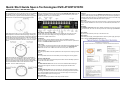
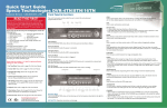
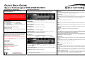
Quick Start Guide
®
Speco Technologies DVR-4TH/8TH/16TH
Customer Service: 1-800-645-5516
200 New Highway, Amityvile, NY 11701
www.specotech.com
Front Panel & Functions
The unit’s front panel controls enable the user to control the unit and preset
programmable functions.
READ THIS FIRST!
Direction Keys
* In Zoom mode, these keys function as Direction Keys.
* In the OSD setup menu, the Direction keys are used to move the cursor to previous or
next fields. To change the value in the selected field, press UP / DOWN keys.
This document is intended to serve as a quick reference page for
initial set-up. It is recommended that the user read the entire
instruction manual before beginning. Basic programming can be
accomplished by simply reading the appropriate instructions first,
then scroll through the easy to operate “On Screen Display” and
make changes.
Please note that the Accessory Kit and Shipping Box contain
the following items:
z 1 – Quick Set-up Guide
z 1 – Power Cord
z 1 – Digital Video Recorder z 1 – IR Controller
z 1 – User’s Manual
z 2 – Rack mount ears
z 1 – CD-Rom (includes manuals, HDD storage calculator and
player software)
Preset Accounts (username, password):
Account 1: admin, 1234
Account 2: user, 4321
Use the same accounts to login local DVR and SpecoRemote™.
The following list represents features that most users will need to
be familiar with. Please review the list and refer to the specific
pages listed in the manual. Please read the appropriate section of
the manual thoroughly and perform the function on the DVR
before attempting to contact technical support.
CALL/COPY
Press to enter Call Monitor Control mode. This is also used to quick export video to an
external devices, including USB DVR+RW and ThumbDrive, etc.
DOME
Press this key to enter Dome Control mode.
LED Definition
The DVR-4TH/8TH/16TH Series LEDs on the front panel are described as follows:
Power LED (Green)
The LED should be lit when the power is connected.
HDD LED (Green)
The LED should be lit while the HDD is processing data.
Alarm LED (Red)
The LED should be lit when an alarm is triggered.
Network LED (Green)
The LED should be lit when the DVR-4TH/8TH/16TH series unit is connected to a
network and blink when any data is being transferred.
REC LED (Red)
The LED should blink while the DVR-4TH/8TH/16TH series unit is recording.
ESC
Press to cancel or exit from certain mode or OSD setup menu without changing the settings.
MODE
Press repeatedly to select desired main monitor display format. There are four viewing
modes available: full screen, 4-window (2×2), 9-window (3×3), and 16-window (4×4).
PLAY/STOP
Press this key to switch between live image and playback video.
FREEZE
• Press FREEZE while viewing live image, the live image will be frozen, but the date/ time
information shown on the monitor will continue updating. The recording of the video will
continue as well. Press FREEZE again to return to live mode.
• Press FREEZE while playing recorded video, the playback video will be paused. Press
LEFT/ RIGHT to move the recorded video reverse/ forward by a single step. Press
FREEZE again to continue playing video.
SEQ(Sequence)
Press to start automatic sequencing of the video coming in from the installed cameras.
Please note that numbers 1 & 2 MUST be performed before
making your first reading.
Please refer to configuration section of User Manual.
SEARCH
In both Playback and Live mode, press SEARCH to access the Search menu to search and
playback recorded video by date/ time, events, or text.
1 Set Time/Date:
2 Format HDD
MENU
Press this key to access the OSD setup menu.
3 Schedule Recording
4 Motion Detect Recording
5 Optimize Record Time/ FPS settings
6 Network & Internet Setup
Function Keys
7 Playback
The DVR-4TH/8TH/16TH series unit function keys on the front panel are described to
the right for normal operation.
8 Video Backup
JOG SHUTTLE: Operation instruction on back page.
Do not block the fan on the unit –
enough airflow is needed to
protect the unit from over heating.
D.D.
Users can trigger warning announcement at certain camera site by pressing the specific
camera key and the digital deterrent key.
ZOOM/ENTER
• In OSD menu or selection interface, press this key to make selection or to save settings.
• In live full screen viewing mode, press to view a 2× zoom image. Press it again to return.
CHANNEL
• In both Live and Playback modes, press any CHANNEL key to view the corresponding
video in full screen. The number of the CHANNEL keys corresponds to the number of
cameras supported by the unit.
• In Dome Control mode, the key “1” is used to access the Set/ Go Preset menu while the
key “2” is used to hide or display the dome camera setting parameters.
Quick Start Guide Speco Technologies DVR-4TH/8TH/16TH
Customer Service: 1-800-645-5516 x196
Rear Panel Connections
The jog/ shuttle knob, shown in the figure below, is a combination
of a shuttle ring with an embedded jog disk, which is used to
provide wide range in playback control. Note that the jog/ shuttle
knob is active only when the DVR unit is in Playback mode.
There are several connectors on the rear panel of the DVR-4TH/ 8TH/ 16TH series unit
available for installations. The following figure shows the connectors by name and a
detailed description of each connector follows.
Audio Out
In addition to the RCA connector, the DVR-4TH/ 8TH/ 16TH series unit provides 4/ 8/ 16
channels of audio exporting accordingly. The Audio Out connectors are provided for
connecting audio output devices (e.g. amplified speakers) to the unit. The PIN of upper row
is for output of each channel while the lower row is for ground.
USB 2.0 (x4)
There are two USB 2.0 ports on the rear panel and two on the front panel to allow users to
connect external USB devices to the unit, such as a ThumbDrive®, DVD+RW, or a USB
mouse.
LAN (RJ45)
The DVR-4TH/ 8TH/ 16TH series unit is capable of networking. Once the unit is connected
to the LAN network, the users can remotely access the unit through SpecoRemote™ on a
PC.
While playing back video, you can use the shuttle ring to select
different speeds of forward and backward playing. Rotating the
shuttle ring causes the unit to playback in fast forward/ backward
playing speed. According to the angle you rotate the shuttle ring,
you can choose the playing speed from 1×, 2×, 4×, 8×, 16×, and
32×, in both forward and reverse directions, shown in the figure
below:
Main Monitor (S-Video/ BNC/ VGA)
S-Video, BNC, and VGA output connectors are available for connecting to a main
monitor. The main monitor displays live image and playback recorded video in
full-screen or multiple window format.
Call Monitor
The call monitor is used to display full screen video of all installed cameras in
sequence. The BNC call monitor connector allows the user to connect an optional call
monitor to the DVR-4TH/ 8TH/ 16TH series unit.
Video Input
A group of BNC connectors is provided for video input streams from installed cameras.
The number of connectors equals to the number of channels. The DVR-4TH/ 8TH/
16TH series unit has 4/ 8/ 16 BNC connectors on the rear panel, respectively.
Video Looping
The other group of BNC connectors positioned on the rear panel is for looping out video
input.
RS-232C
The unit provides a RS-232C communication port for sending and receiving signals.
Inside the shuttle ring is the jog disk, shown in the illustration
below, it can be turned completely in either direction. Once you
freeze the video, you can use the jog disk to go to single-step
play back. Clockwise rotation causes forward one-step playback;
and counterclockwise rotation causes backward one-step
playback. This is for JPEG recoding only.
Alarm I/O & RS-485 Port
The unit provides Alarm I/O and RS-485 ports that offer users the flexibility required to
connect the unit to other devices.
NAS
The DVR-4TH/ 8TH/ 16TH series unit can connect to a Network Attached Storage
(NAS) device through this connector to increase storage space and allow vast
recording.
Audio In
The DVR-4TH/ 8TH/ 16TH series unit provides 4/ 8/ 16 channels of audio recording
accordingly. The Audio In connectors are offered for connecting audio source devices
(e.g. external amplified microphone) to the unit. The PIN of upper row is for input of
each channel while the lower row is for ground.
Main Audio Out
One RCA connector is provided for audio output of main monitor.
Power Switch
The power switch is used to power up or shut down the unit.
Power Supply
Connect the power supply cord shipped with the unit to the power supply jack to provide
power to operate the DVR-4TH/ 8TH/ 16TH series unit.