1
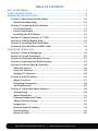
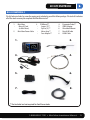
1-888-628-1730 • Mini Maxx Installation Manual
1
WARNING!
THIS IS A HIGH PERFORMANCE PRODUCT TO BE USED AT YOUR OWN RISK!
Do not install this product until you have read and fully understand the following disclaimer of liability. The following disclaimer of liability sets forth the terms and conditions for the installation and/or use of this product. By
installing this high performance product, the buyer acknowledges that they have read and fully understand this
disclaimer and accepts its terms and conditions.
DISCLAIMER OF LIABILITY
H&S Performance, LLC and their successors, distributors, jobbers, dealers, and retailers (SELLER) shall in no way be responsible for any direct, indirect, or consequential damage resulting from improper installation and/or use of this product. The
BUYER/USER assumes all responsibility for any damage resulting from the use or misuse of this product The buyer hereby
waives all liability claims for the use of this product.
The BUYER acknowledges that he/she is not relying on the SELLER’s skill or judgment to select or furnish goods suitable for
any particular purpose and that there are no liabilities which extend beyond the description herein, and the BUYER hereby
waives all remedies or liabilities, expressed or implied, arising by law or otherwise, (including without any obligations of the
SELLER with respect to fitness, merchantability and consequential damages) or whether or not occasioned by the SELLER’s
negligence.
The SELLER disclaims any warranty and expressly disclaims any liability for personal injury or damages. The BUYER acknowledges and agrees that the disclaimer of any liability for personal injury is a material term for this agreement and the BUYER
agrees to indemnify the SELLER and to hold the SELLER harmless from any claim related to the product purchased. Under no
circumstances will the SELLER be liable for any damages or expenses by reason of use or sale of any such products.
The SELLER assumes no liability regarding the improper installation, misuse, or misapplication of its products. It is the buyer
and/or installer’s responsibility to check for proper installation.
LIMITATION OF WARRANTY
H&S Performance, LLC (“SELLER”) gives Limited Warranty as to the description, quality, merchantability, fitness for any product’s purpose, or any other matter of SELLER’s product sold herewith. The SELLER shall be in no way responsible for the product’s use and service and the BUYER hereby waives all rights other than those expressly written herein. This Warranty shall not
be varied except by a written agreement signed and dated by SELLER and BUYER.
The Warranty is Limited to one (1) year from the date of sale and limited solely to the parts contained within the product’s
original packaging. All products that are in question of Warranty must be returned shipping prepaid to the SELLER and must
be accompanied by a dated proof of purchase receipt. All Warranty claims are subject to approval by H&S Performance, LLC.
Under no circumstances shall the SELLER be liable for any labor charges incurred, or travel time incurred in diagnosis for
defects, removal, or re-installation of this product, or any other contingent expenses. Any product deemed defective and
consequently repaired or replaced by SELLER, shall retain the remainder of the warranty period from date of purchase, as the
warranty period shall not be extended due to repair or replacement. Under no circumstances will the SELLER be liable for any
damage or expenses incurred by reason of the use or sale of any such product.
If the buyer does not agree to the terms of this limited warranty or the disclaimer of liability, the buyer may return this product
to the SELLER in a new and unused condition, along with dated proof of purchase, within 30 days of purchase, for a full refund.
This warranty is null and void for any new products purchased through unauthorized dealers.
This warranty is null and void for any products sold as USED or REFURBISHED.
This warranty is null and void for any products purchased below the H&S UNILATERAL PRICING POLICY
Mini Maxx Installation Manual • www.hsperformance.com
EMISSION DELETE TUNING:
Emission delete tuning is for RACE USE ONLY, or where emissions equipment is not required
by law. If instructed by your H&S product please visit www.hsperformance.com to
download emissions delete tuning. Product registration is required.
INTERNET UPDATES:
H&S Performance regularly issues free internet updates and custom tuning options for the
Mini Maxx. Please check to see if there are any available for your truck by going to:
www.hsperformance.com
TROUBLESHOOTING:
Please read and understand all installation instructions before proceeding with the
installation.
If you have questions during the installation of this product, please call H&S Performance
support at 1-888-628-1730
1-888-628-1730 • Mini Maxx Installation Manual
TABLE OF CONTENTS
BILL OF MATERIALS................................................................................................. 5
PARTS DESCRIPTIONS............................................................................................. 6
MINI MAXX INSTALLATION.................................................................................... 9
Section 1: Mounting the Mini Maxx..............................................................10
Windshield Mounting..................................................................................10
Section 2: Installing the Pyrometer...............................................................11
Pre-Turbo Mount..........................................................................................12
Post-Turbo Mount.........................................................................................13
Installing the PCH Board.............................................................................14
Section 3: Dodge Cummins 6.7 EGR..............................................................15
Section 4: OBDII Adapter plug.......................................................................16
Section 5: Installing the Power Wire..............................................................17
Section 6: Run Mini Maxx HDMI Cable..........................................................18
MINI MAXX OPERATION....................................................................................... 19
Section 1: Button Navigation.........................................................................19
Section 2: Install Download............................................................................20
Section 3: Exploring the Main Screen...........................................................21
Section 4: Exploring the Menu System.........................................................23
Section 5: Vehicle Specific Features..............................................................24
GM 6.6l Features...........................................................................................24
Ford 6.4L Features........................................................................................25
Dodge 6.7L Features....................................................................................26
Section 6: Vehicle Setup..................................................................................27
Adjust Tire Size..............................................................................................27
Defueling Parameters..................................................................................28
Set Defuel Levels..........................................................................................29
Section 7: Other Mini Maxx Features............................................................30
Gauge Setup..................................................................................................30
Adjust Backlight...........................................................................................31
Change Background Color..........................................................................32
Adjust Volume Setting.................................................................................32
Diagnostics....................................................................................................33
Reset to Default Setting..............................................................................34
Show Settings...............................................................................................35
Micro SD Card................................................................................................35
Mini Maxx Installation Manual • www.hsperformance.com
BILL OF MATERIALS
BILL OF MATERIALS
The list below includes by name the major parts included in your Mini Maxx package. The tools list indicates
all of the tools necessary to complete the Mini Maxx install.
1. Mini Maxx
• Micro SD Card
(in Mini Maxx)
2. Mini Maxx Power Cable
3. PCH Board**
• Screws (2)**
• Zip Ties (4)**
• Velcro Strip**
• Fuse Adapter**
4.
5.
6.
7.
8.
Pyrometer Probe**
OBDII Adapter
Windshield Mount
Mini USB Cable
HDMI Cable
1.
2.
3.
4.
5.
6.
7.
8.
** Not included and not required for Ford Powerstroke.
1-888-628-1730 • Mini Maxx Installation Manual
5
PARTS DESCRIPTION
PARTS DESCRIPTION
This section describes each of the parts in the Bill of Materials, the descriptions provide a physical set of
attributes and a purpose for each part. The parts descriptions also list everything that is included in each
assembly.
The Mini Maxx Head Unit
The main component is the Mini Maxx Head Unit. The Head
Unit is the interface in which you control vehicle performance parameters. It is also the brains that will save vehicle
activity and defuel a vehicle. Notice that the head unit has:
seven total buttons, five on the left side and two on the right,
a large color screen, and an electronic plug for docking on
the back. Note that this is the last piece that you will install.
Note: Mini Maxx includes a micro SD card inserted
in the side of the Head Unit.
Power Cable
The Power cable connects the OBD ll Adaptor Plug to the vehicle fuse box to supply power to the Mini Maxx. It is optional
to use as there are two ways to power up your Mini Maxx
1. (Recommended) Use this power cable and wire it to the
designated location specified later in this manual.
2. The OBD II port provides constant 12V+ power, so your
Mini Maxx can power off of the OBD II port alone. But in
this situation the Mini Maxx will not turn on and off with
the ignition. There is a switch on the OBDII adapter plug
in order to turn the Mini Maxx on and off.
OBDII Adapter Plug
The OBDII Adapter is a communication hub for the Mini Maxx.
The OBD ll Adaptor plugs directly into the vehicle OBD ll port. Notice the OBD ll Adaptor has many ports to
support various other functions of the Mini Maxx.
Pyrometer Connection Head (PCH) Board Assembly*
The PCH Board or Pyrometer Connection Head serves as a dock to connect the pyrometers into the Mini
Maxx system. The PCH Board includes the ability to connect two pyrometers. Attached to the PCH Board
housing is a cable with four pin plug which connects to the OBDII Adapter Plug. The list below includes all
separate parts that make up the entire PCH Board Assembly.
• PCH Board
• Velcro
• (2) Self-tapping Sheet Metal Screws
• Pyrometer Cable
* Not included, Not required for
Ford Powerstroke
Universal Windshield Mount
This universal windshield mount is used to install the Mini Maxx firmly onto the windshield, it is a suction
cup mount that will work on any vehicle windshield. Check our web site for other mounting options, the Mini
Maxx is adaptable to a range of other mounting styles.
1-888-628-1730 • Mini Maxx Installation Manual
7
PARTS DESCRIPTION CONTINUED
Mini USB Cable
Use this cable to connect your Mini Maxx to your personal computer to install software updates. Visit
www.hsperformance.com in the downloads section for product updates. Please find your product application and follow the posted instructions there to update your Mini Maxx.
HDMI Cable
The HDMI Cable connects the Mini Maxx to the OBD ll Adapter Plug and acts as the main line of communication for the Mini Maxx.
8
Mini Maxx Installation Manual • www.hsperformance.com
MINI MAXX INSTALLATION
INSTALLATION OVERVIEW
The installation overview illustrates a totally installed and functional Mini Maxx system. This overview is
meant to help reference the general location of installed parts and pieces of the Mini Maxx. Notice that there
are different overview diagrams. Use the correct diagram for your truck.
DODGE CUMMINS ‘07.5-’10
GM DURAMAX‘07.5-’10
Mini Maxx & Windshield Mount
Fire wall grommet
Fuse Box
Pow
(Op er Cab
tion le
al)
OBDII Adapter Plug
OBDII Port
FORD POWER STROKE ‘08-’10
MINI MAXX &
Windshield mount
HDMI Cable
OBDII Port
OBDII Adapter Plug
Power Wire
(Optional. To purple
ignition
wire under dash)
1-888-628-1730 • Mini Maxx Installation Manual
9
INSTALLATION CONTINUED
MINI MAXX INSTALLATION INSTRUCTIONS
SECTION 1: MOUNTING THE MINI MAXX
In this section you will decide where to mount the Mini Maxx Cradle, so you are essentially choosing the location for the Mini Maxx inside the vehicle cab. First, decide which mounting style you will choose for the Mini
Maxx; we offer two different styles of mounting:
1.Windshield mounting
2.Custom Pod mounting (Refer to the instructions included with your custom pod)
Visit hsperformance.com for custom options
WINDSHIELD MOUNTING
1. Locate the T-shaped mount socket on the back side of the Mini Maxx.
2. Notice that the top of the universal mount will fit into T-shaped socket and slide forward to
secure the Mini Maxx to the mount.
3. With the Mini Maxx connected to the mount use the windshield mount to secure the Mini Maxx
to the wind- shield. Be sure that the position of the Mini Maxx does not obstruct the view of
the road or distract the driver from their primary responsibility, which is driving responsible.
10
Mini Maxx Installation Manual • www.hsperformance.com
SECTION 2: INSTALLING THE PYROMETER AND THE PYROMETER CONNECTION HEAD (PCH)
* If you are installing on a Powerstroke, you can skip this section. Ford Powerstroke trucks
come with a pyro from the factory. The Mini Maxx will automatically read from the factory sensor.
In this section you will drill and tap the Pyrometer Probe in the exhaust, either pre-turbo or postturbo as a means to collect exhaust gas temperatures (EGT). Exhaust gas temperatures indicate
how hot the motor is getting and can be used to set safety defueling parameters.
POST-TURBO VS. PRE-TURBO
You must decide between mounting the Pyro Probe either post-turbo or pre-turbo. The difference in
location determines what temperatures will read on your Mini Maxx. Pre-turbo mounting is generally recommended because it provides more accurate EGT readings.
The Mini Maxx is capable of running two pyrometers simultaneously. Please purchase an extra
probe, if you wish to read pre AND post turbo pyrometers.
1-888-628-1730 • Mini Maxx Installation Manual
11
INSTALLATION CONTINUED
PRE-TURBO MOUNT
1. Drill a 5/16” hole into the exhaust manifold where
all the exhaust runners of the manifold come together, just before the turbo exhaust inlet. Then
tap the hole with a 1/8” pipe tap and mount the
Pyrometer Probe in the hole. Use a 9/16” wrench
to tighten the probe holder or tube fitting to the
down tube. Then tighten the Pyro Probe Cap to
the holder using a 5/8” wrench.
2. Run the Pyro Cable up to engine bay; let the end
of the cable sit while installing the PCH Board.
GM Pre-Turbo Mount
WARNING: If any debris such as drill bits and
metal shavings drop inside the manifold, we advise
that the manifold be removed from the vehicle so
that the debris can be removed before starting the
vehicle again.
Dodge Pre-Turbo Mount
TOOL TIP, PRE-TURBO MOUNT
When drilling into the exhaust manifold, metal spews, shavings, and broken drill bits can fall inside. This
can be hazardous to your turbo when the engine starts. Try doing four things to avoid this possible problem. One, use a high quality twist bit and a slow speed drill, about 500-800 rpm. Two, start with a small
pilot bit about 1/8”, then use the full 5/16” bit after the smaller one has punched through. Three, grease your
drill bit in addition to the normal lubricant, this will catch flying spews as they are cut. Four, just prior to
punching through into the inside of the manifold, start the engine and build up exhaust pressure on the
inside of the manifold (blows spews outside the manifold instead of letting them fall inside).
12
Mini Maxx Installation Manual • www.hsperformance.com
POST-TURBO MOUNT
1. Find a location on the exhaust pipe that is 3-6”
downstream from the turbo charger output. Then
drill a 5/16” hole and run a 1/8” pipe tap into the
hole. Mount the Pyrometer Probe in the threaded
hole using a 9/16” wrench to tighten the probe
holder or tube fitting to the down tube. Then
tighten the Pyro Probe Cap to the holder using a
5
/8” wrench.
2. Run the Pyro Cable along the brim of the engine
bay, and then let the end sit when installing the
PCH Board.
Dodge Post-Turbo Mount
Securing Pyro
Pyro line secured
1-888-628-1730 • Mini Maxx Installation Manual
13
INSTALLATION CONTINUED
INSTALLING THE PCH BOARD
The pyrometer that was installed will now have to be connected to the PCH Board, but first the PCH
Board needs to be mounted in a secure location that both of the pyrometer ends can reach.
1. Gather all of the parts of the PCH Board assembly:
• Pyrometer Connection Head with PCH Cable
• Self-tapping Sheet Metal Screws
• Velcro
• Jumper
• Zip Ties
2. The PCH Board needs to be mounted in a location
that is secure (away from extreme heat and moving parts), and in a location in which the end of
the Pyrometer Cable can easily reach.
3.Use the sheet metal screws or Velcro, or both to
securely attach the PCH Board to a safe location
within the engine bay.
4.To connect the end of the Pyrometer Cable to the PCH Board, first remove the screw and nut on
the end of the pyrometer leads, then remove the screws from the Pyro 1 heads on the PCH Board.
Use those screws to secure the Pyrometer Cable leads to the PCH Pyro 1 heads, see the PCH Assembly Diagram (pg. 19) for a visual reference when connecting the pyrometer leads to the PCH
Board.
Notice: Do not remove the jumper from the Pyrometer 2 location unless you are
installing a second pyrometer.
If connecting two pyrometers keep track of which location, Pyro 1 or 2, each
pyrometer was attached to on the PCH Board
5.Once the PCH Board is secure and the pyrometer is connected to the PCH Board, use zip ties to secure
the pyrometer cables away from extreme heat and moving parts.
6.Run the end of the PCH Cable through the fire wall. It will need to be connected to the OBDII Adapter
Plug. Use zip ties to secure all remaining cable left inside the engine bay.
14
Mini Maxx Installation Manual • www.hsperformance.com
SECTION 3: DODGE CUMMINS 6.7 EGR
This section is ONLY for DPF Delete tuning on 6.7L Dodge Cummins. On all other models,
the EGR is automatically turned off. DPF Delete tuning is for RACE USE ONLY!
2010 6.7L Cummins EGR
For 2010, Cummins has changed their EGR programming. It is no longer necessary to unplug the EGR system
if you are installing DPF delete tuning on a 2010 6.7L Cummins. You can still, however, remove the entire
EGR system using an H&S EGR Delete kit. Whether you decide to remove the entire EGR system, or leave it
plugged in as factory, the EGR will NOT function and will NOT throw check engine lights.
For all H&S Race tunes, EGR MUST BE TURNED OFF!! To turn off EGR flow, please follow steps
below. EGR can be blocked or removed as well, but the following steps MUST be taken for
trouble free operation.
1. Locate EGR Throttle Control Valve Assembly (Fig.1). Assembly is located between
intercooler and intake manifold on drivers side of engine compartment.
2. Unplug EGR Throttle Control Valve wire harness. Harness is LIGHT GRAY in color and
is located on back side of Throttle Valve Assembly, and is not directly visible when
looking at assembly from above. It is recommended to view from below engine to
determine correct angle for removal. **Note** There is a red lock tab that must be
moved sideways in order to remove the harness.
3. Locate EGR Solenoid on top of intake horn, on drivers side (Fig 2). It is directly visible
when looking at intake horn, and faces towards front of truck.
4. Unplug EGR Solenoid wire harness. Connector is Brown in color.
5. Install EGR block-off plates, if desired.
1-888-628-1730 • Mini Maxx Installation Manual
15
INSTALLATION CONTINUED
SECTION 4: OBDII ADAPTER PLUG
This step involves locating the vehicle’s OBD ll port and
then simply plugging the OBD ll Adapter Plug into the
OBD ll port.
1. As the illustration below shows, OBD ll ports
are always located somewhere under the drivers side dash. The OBD ll port is a male receiver
that will have the same shape as the end of the
OBD ll Adaptor plug.
2. Once the OBD ll port is located, then simply
plug the OBD ll Adaptor plug into the OBD ll
port.
Possible OBDII Port Locations
(location may vary)
OBDII ADAPTER PLUG DIAGRAM
1. OBD ll Male end: this is the part of the adapter plug that plugs into the vehicle OBD ll port.
2. Main harness port: the main harness will plug into the Mini Maxx and into this port during installation.
3. Power wire port: the power wire will run from this port to the vehicle fuse box during installation.
Plug into the Mini Maxx and into this port during installation.
4. Power supply switch: use this switch to change power from running off of the Power Wire to OBD ll
power as a power supply for the Mini Maxx.
5. Four pin usb: This port is used if an H&S pyrometer kit is purchased for the Mini Maxx.
6. Five pin usb
7. Adapter plug fuse
1
2
5
3
6
7
4
16
Mini Maxx Installation Manual • www.hsperformance.com
SECTION 5: INSTALLING THE POWER WIRE (*OPTIONAL)
*The OBD II port provides constant 12V+ power, so your Mini Maxx can power off of the OBD II port alone.
But in this situation the Mini Maxx will not turn on and off with the ignition. There is a switch on the OBDII
adapter plug in order to turn the Mini Maxx on and off.
In this section you will run the Power Wire coming from the Mini Maxx Cradle to the vehicle fuse box and
connect it to the fuse locations specified below. The fuse location for the Power Wire is different on each
vehicle application.
CONNECTING THE POWER WIRE:
1. For Dodge and GM trucks the fuse boxes are located on the driver’s side of the vehicle inside the engine
bay. Please see your owner’s manual for more details on fuse box locations. Once inside the fuse box,
locate the appropriate fuse depicted in the vehicle-specific pictures below. For Ford trucks route power
wire underneath drivers side dash and connect it to the purple ignition wire shown in picture below.
Power Wire w/90º Connector
‘07 - ‘10 GM Fuse Box
(Fuse number 45)
2010 Dodge Fuse Box
The fuse numbers shown are
the typical locations.
Your model MAY BE DIFFERENT.
Use a test light or multimeter
to verify you have 12v with
ignition ON.
‘07 - ‘09 Dodge Fuse Box
‘08 - ‘10 Ford Power Wire
(Fuse number M45)
(Fuse number 28)
(Capped from the factory)
2. Remove the fuse, indicated in the pictures, and insert the fuse jack. Make sure that the fuse jack
is placed on the dead side of the fuse to ensure that the Mini Maxx is protected by the fuse. Use
a volt meter to verify the dead side of the fuse. With the fuse pulled and the truck powered on
but not started, the volt meter should read 0 volts on the fuse jack to ground. Problems that can
occur if the incorrect fuse is used for this connection: the power may stay on continuously even
with the key off; or, the Mini Maxx can receive power at the incorrect time of the power-on/
starting cycle of the vehicle.
3. Run the power wire through the fire wall before preparing the Power Wire. Prepare the Power
Wire by stripping the end of the wire about ¼”. Connect the blue 90° connector to the end of the
Power Wire using crimping pliers.
4. Connect the Power Wire to the fuse jack, place the fuse back into the slot, and close the fuse box.
1-888-628-1730 • Mini Maxx Installation Manual
17
INSTALLATION CONTINUED
SECTION 6: RUN MINI MAXX HDMI CABLE
In this section you will connect the Mini Maxx HDMI cable to the OBD ll Adaptor plug and then run the other
end of the HDMI cable up the side of the vehicle dash and connect it to the back of the Mini Maxx.
1. Plug one end of the HDMI cable into the Main Harness port on the OBD ll adapter plug.
2. Run the other end of the HDMI cable up through the vehicle dash on the drivers side so that the end of
the cable emerges from the dash near the vehicle A-pillar. It may be necessary to temporarily remove
the vehicle weather stripping and dash panel to achieve an installation where the HDMI cable cannot
be seen.
3. Plug the HDMI cable into the back side of the Mini Maxx, make sure that there is enough slack in the
cable to accommodate mounting the Mini Maxx to the windshield.
Mini Maxx
HDMI Cable
OBDII Plug
Power Cable
Almost Done!
You need to install the download now. Read the next section for Install Download procedure.
18
Mini Maxx Installation Manual • www.hsperformance.com
Mini Maxx OPERATION
MINI MAXX OPERATING INSTRUCTIONS
These operating instructions are split into sections:
• SECTION 1: Button Navigation
• SECTION 2: Install Download
• SECTION 3: Exploring the Main Screen
• SECTION 4: Exploring the Menu System
• SECTION 5: Vehicle Specific Features
• SECTION 6: Vehicle Setup
• SECTION 7: Other Mini Maxx Features
SECTION 1: BUTTON NAVIGATION
Press the top left button to enter the Main Menu, also use this button to exit menus.
Speed
MPH
Press any of the four buttons on the left to
select items on the screen that are adjacent to
the button position.
In general these buttons work as up and down
buttons, they may also be used to select items
on the screen adjacent to these buttons.
1-888-628-1730 • Mini Maxx Installation Manual
19
SECTION 2: INSTALL DOWNLOAD
The Install Download option is used to install tuning onto a vehicle, or return a vehicle to stock.
1.Press Menu: To get into the Mini Maxx main menu.
2.Select Install Download: You may have to “Arrow Down” or “Arrow Up” to find this option.
3.Install a download onto a stock vehicle: If the vehicle is stock and you enter the install download
menu, simply follow the screen prompts to install a download on the vehicle.
Change Download Settings: If the vehicle already has a download on it from the Mini Maxx that is
currently installed on that vehicle. This option is used to install updated or custom tuning. Updated and
Custom tuning can be download for the H&S Performance website.
Return a vehicle to stock: To completely return a vehicle to its factory stock conditions you need to
select this option. This is highly recommended when taking the vehicle in for any kind of service.
Go Back
DOWNLOAD INSTALLED
Download Already Installed
Change Settings
Return to Stock
This Mini Maxx screen shot shows what you will see if a download has already been entered into a vehicle.
Before installing the download:
• Make sure that the Mini Maxx is properly plugged in.
• Make sure that the harness is properly installed.
• The vehicle battery is fully charged.
• The vehicle is warmed up to operating temperature.
THE MICRO SD CARD MUST BE INSERTED IN THE SIDE OF THE MINI
MAXX TO DOWNLOAD TO A VEHICLE.
20
Mini Maxx Installation Manual • www.hsperformance.com
Mini Maxx OPERATION CONTINUED
SECTION 3: EXPLORING THE MAIN SCREEN
The Main Screen is where you view all of the vehicle activity. In this section you will learn how to navigate
the Main Screen and learn about all of the different parts of the Main Screen.
MAIN SCREEN NAVIGATION
Below are descriptions of how all of the Mini Maxx buttons work and what they do while in the Main
Screen. The buttons perform different functions while in a menu or submenu.
Press the top left button to enter the Main Menu, also use this button to exit menus.
Menu
Speed
RPM
Throttle
Coolant
MPH
60
MPH
RPM
X
ºF
Press any of the four buttons on the left that
coincide with the four vehicle parameters to
display that particular vehicle parameter on the
large gauge in the upper right side of the screen.
Hold a button down to view the different graph
types for the large gauge.
90
120
30
0
Power Level Setting
not available until
download is installed.
Power Level Up
Power Level Down
Use the power level buttons to control power
levels on-the-fly only while in the main screen
1-888-628-1730 • Mini Maxx Installation Manual
21
MAIN SCREEN PARTS DESCRIPTION
This section will describe all of the different parts of the Main Screen.
The black bar: The black bar highlights the title of one of the four displayed vehicle parameters to indicate
that vehicle parameter is also being displayed on the large gauge.
Menu button: press to enter the main menu.
Menu
Speed
RPM
Throttle
Coolant
Large Gauge
MPH
MPH
RPM
X
ºF
90
60
120
30
0
Power Level Setting
not available until
download is installed.
Vehicle parameters: To change which vehicle
parameter is displayed in the large gauge area
simply press one of the four buttons next the
preferred vehicle parameter.
Power level text: Displays which power level is
active, whether it be: Stock, Mild, Wild, or Hot.
Note: This will not be active if the Download has
not been installed.
22
Mini Maxx Installation Manual • www.hsperformance.com
Mini Maxx OPERATION CONTINUED
SECTION 4: EXPLORING THE MENU SYSTEM
The diagram below shows all of the Main Menu items and explains the Main Menu navigation.
This button is used to enter into the Main Menu
from the main screen. While in any of the menus
this button works as a back button.
Go Back
to Main Screen
Navigation through the main menu: Use the
large Up Down Buttons to page up and
page down through all the Main Menu options.
MAIN MENU
Install Download
Gauge Set Up
Set User Options
Set Defuel Levels
Adjust Tire Size
Diagnostics
Show Settings
These buttons are used
to enter into the sub
menus from the main
menu and may also be
used to select additional
items when in the sub
menus.
Update Black Maxx™ Software
1-888-628-1730 • Mini Maxx Installation Manual
23
Mini Maxx OPERATION CONTINUED
SECTION 5: VEHICLE SPECIFIC FEATURES
GM 6.6L FEATURES
SPEED LIMITER (GM 6.6L)
The Mini Maxx gives racing enthusiasts the option to adjust the OEM speed limiter. This allows the vehicle to
reach speeds in excess of where the OEM speed limiter was set. By selecting yes to remove the speed limiter
you agree that your vehicle has tires rated for speeds in excess of 140 mph. Do not attempt to operate the
vehicle at speeds higher than the posted speed limit.
TRANSMISSION RE-LEARNING (GM 6.6L)
Performing a Transmission Reset is VERY important! A reset must be done to re-train the transmission to
perform correctly with added horsepower.
CAUTION! When re-training the transmission, a series of 0-80 MPH Wide Open Throttle(WOT) runs are necessary for proper transmission shifting. ALWAYS follow posted speed limits. DO NOT attempt WOT runs in adverse
weather conditions such as snowy, icy, rainy or other conditions which may affect your vehicles traction, or
impair your visibility.
After download is complete, turn key to ON position. From the general display screen(initial start-up screen),
press top left button to take you into the main menu screen. Use the down arrow on the right side of the unit to
scroll down to “Reset Transmission”. Press the button on the left side to agree to the transmission reset. Press the
corresponding button on the left hand side of the unit to reset the transmission.
Once reset, it is highly recommended to perform a series of (3) 0-80 MPH runs immediately following each
download.
It is recommended that the Transmission learning process be done while in the “Hot” setting on your Mini Maxx
Tuner.
1.
0-80MPH @ 1/4 throttle position, then slow down and come to a complete stop
2.
0-80MPH @ 1/2 throttle position, then slow down and come to a complete stop
3.
0-80MPH @ wide open throttle position, then slow down and come to a complete stop
24
Mini Maxx Installation Manual • www.hsperformance.com
FORD 6.4L FEATURES
TIRE SIZE CALIBRATION (FORD 6.4L)
During the programming of the Ford 6.4L Powerstroke the Mini Maxx will ask if you would like to adjust your
factory tire size to calibrate your factory speedometer. Please make the necessary adjustments and follow the
on screen instructions. This tire size adjustment can only be done when installin or reinstalling tuning software
on truck. if at any point you would like to change your tire size, select menu, install download, agree to the
disclaimers, and select change settings. Follow the on screen instructions.
TRANSMISSION RE-LEARNING (POWERSTROKE 6.4L)
IMPORTANT! During the programming of the Ford 6.4L Powerstroke the automatic transmission is cleared of all
memory and must be re-learned. During this re-learn process you may experience hesitation during shift, hard
shift, or defuel patterns. This is normal and you should continue through the learning process.
CAUTION! When re-training the transmission, a series of 0-80 MPH Wide Open Throttle(WOT) runs are necessary for proper transmission shifting. ALWAYS follow posted speed limits. DO NOT attempt WOT runs in adverse
weather conditions such as snowy, icy, rainy or other conditions which may affect your vehicles traction, or
impair your visibility.
Once your download is installed, please follow these steps to set-up your transmission correctly.
It is recommended that the Transmission learning process be done while in the “Hot” setting on your Mini Maxx
Tuner.
1.
0-60MPH @ 1/4 throttle position, then slow down and come to a complete stop
2.
0-60MPH @ 1/2 throttle position, then slow down and come to a complete stop
3.
0-80MPH @ wide open throttle position, then slow down and come to a complete stop
IMPORTANT! On any truck using larger than 3” lift blocks under the rear leaf pack, it is HIGHLY
RECOMMENDED to install traction bars. On 60+ HP Tune, failure to do so may result in harsh shifting and may
cause premature transmission and/or drive line damage.
1-888-628-1730 • Mini Maxx Installation Manual
25
Mini Maxx OPERATION CONTINUED
DODGE 6.7L FEATURES
To make any changes, you must have the Engine Off and the Drivers Door Closed.
TIRE SIZE CALIBRATION
This option will recalibrate your factory speedometer to adjust for non-stock sized tires or gearing. This feature
works exactly the same as the Adjust Tire Size feature, except that Adjust Tire Size only affects the speed displayed on the Mini Maxx.
SPEED LIMITER
During the download process, you will be asked if you would like to remove the speed limiter. Follow the on
screen prompts to make your selection. Do not attempt to operate the vehicle at speeds higher than
the posted speed limit.
IDLE UP
Enables / Disables the use of the high idle feature. Follow your Chrysler owners manual to use this feature. It will
use the cruise control buttons to control idle RPM.
AUTO DOOR LOCK
Enables / Disables the automatic door locking when the vehicle reaches a certain speed.
HEAD LAMP DELAY
Enables / Disables the head lamp delay.
HORN CHIRP ON LOCK
Enables / Disables the horn chirp when locking the vehicle.
OPTICAL CHIRP ON LOCK
Enables / Disables the parking lights flashing when locking the vehicle.
UNLOCK DRIVER DOOR
Enables / Disables unlocking the driver door only when pushing the unlock button on the key-fob. When enabled your vehicle will require a double push of the unlock button to unlock all doors.
SEAT BELT MINDER
Enable / Disable the chime and light for the drivers seat belt system.
ACCESSORY DELAY
Enable / Disable the time delay your radio and accessory system will stay on after the key has been turned off.
FOGS W/HIGHS
Enable / Disable the fogs staying on when the high beam lights are being used.
DAYTIME LIGHTS
Enable / Disable daytime running lights.
26
Mini Maxx Installation Manual • www.hsperformance.com
INSTRUCTIONS CONTINUED
SECTION 6: VEHICLE SETUP
This section describes various non-vehicle specific features of the Mini Maxx
ADJUST TIRE SIZE
The tire size function allows you to adjust the speed that the Mini Maxx will display in one of the
gauge locations to account for larger or smaller than stock tire sizes. The range of tire sizes that
the Mini Maxx will adjust for starts at 28” and goes up to 39” and it adjusts in increments of .25”.
31.0
31.25
31.50
DEFAULT
DEFAULT
32.0
* Accurate only if
ECM tire size
setting are at
default factory
values.
Notice that the selected tire size is displayed
in the box on the left side of the screen. Once
the correct speed is highlighted simply press
the go back button to exit. Your selection will
automatically be saved.
32.25
32.50
32.75
Use the Up and Down buttons to scroll
through the available tire sizes; highlight the tire
size that fits what is currently mounted on the
vehicle to display the speed accurately.
Default setting:
The default setting reads the speed directly off of the vehicle’s computer. Use this setting if you have
already calibrated the speedometer for larger or smaller aftermarket tires.
To adjust the factory speedometer, please use the Tire Size Calibration feature.
Adjust Tire Size will only affect the speed that is displayed on the Mini Maxx.
1-888-628-1730 • Mini Maxx Installation Manual
27
DEFUELING PARAMETERS
Set up defueling parameters based on a number of different vehicle parameters. In this menu you
can also turn vehicle parameters off. The defueling parameters available are vehicle specific, so not
all defueling parameters are available for every make and model.
By default the Mini Maxx is setup to automatically limit the power level until the vehicle has reached
operating temperature. This will keep the unit in “No Power” until vehicle is warmed up. This feature
is highly recommended, and will reduce wear & tear on the engine. If you wish, this feature can be
turned off.
Go
Back
to Main Menu
DEFUEL MENU
Pyro 1 Temperature Level
Setting: 600˚F
Pyro 2 Temperature Level
Setting: 1250˚F
Engine Coolant Temp Level
Setting: 210˚F
Boost Level
Setting: 23PSI
Transmission Temperature
Setting: 260˚F
Oil Temperature
Setting: 210˚F
Press to enter set up menu for defuel items.
Current setting are displayed in Defuel Menu
Default Defueling Settings
Pyro 1 Temperature Level
1450˚F
Pyro 2 Temperature Level
OFF
Engine Coolant Temp Hot
220°F
Engine Coolant Temp Cold (cold start protection) 140°F
Boost Level
OFF
Transmission Temp Level
OFF
Oil Temperature
OFF
28
Use the Up Down Buttons to scroll up and
down through the different sub menu items.
Here is a list of all of the defueling capabilities
for the Mini Maxx. All defueling options can be
activated at the same time, all can be turned off,
or a mix of on and off. Each defueling option is
adjusted individually to be on or off and set to a
particular defueling temperature.
Mini Maxx Installation Manual • www.hsperformance.com
SET DEFUEL LEVELS
When entering a setup menu for any of the defuel options the menu will have a list of defuel levels
to select from based on that specific defuel parameter. The selected value is displayed on the left, to
select a defuel level you need only highlight the amount and then exit the setup menu. To turn any
particular defuel parameter off press the bottom left button.
Go
Back
to Defuel Menu
The selected Defuel value
for PYRO 1 is displayed
in the box below:
Selected
1400º F
DEFUEL ON
PYRO1
Set Deful Level
Defueling Levels
1250
1350
1400
1450
1500
1550
DEFUEL OFF
Use this button to turn the defueling on.
Go
Back
to Defuel Menu
up
1300
1600
down
Use the large Up Down Buttons to scroll up
and down through the different sub menu items.
PYRO1
Set Deful Level
The selected defuel value
for PYRO 1 is displayed
in the box below:
Selected
OFF
DEFUEL ON
DEFUEL OFF
Use this button to turn the defueling off.
1-888-628-1730 • Mini Maxx Installation Manual
29
SECTION 7: OTHER MINI MAXX FEATURES
This section describes all the customizing features of the Mini Maxx.
GAUGE SETUP
Enter to change the vehicle parameters displayed on the four gauge locations in the Main Screen. This is
also where you can see all of the most up-to-date vehicle parameters available to your vehicle make and
model after running an internet upgrade.
Selecting a vehicle parameter to display in a particular location is done by highlighting the gauge location and
then highlighting the desired vehicle parameter.
Once the correct vehicle parameter for a gauge location has been highlighted, you do not need to press another
button to select that vehicle parameter. Simply highlighting the vehicle parameter makes it active in that location.
Notice that upon entering the gauge setup menu that, Set Gauge 1, is highlighted in black. When a gauge
location is selected it is highlighted in black on the left and it also appears above the vehicle parameter
selection box.
Go
Back
to Main Menu
GAUGE SETUP
Set Gauge 1
Gauge 1
Speed
Set Gauge 2
Use the Up and Down Arrows
to Change the Gauge Function
RPM
Set Gauge 3
Throttle
Pyro 2
Speed
Boost
Set Gauge 4
Coolant
To highlight a different gauge location press the
selection button that coincides with that gauge
location. So to select gauge location 1, press the
second button down on the left hand side of the
Mini Maxx. To select the 4th gauge location press
the bottom button or the 5th button down on
the left side.
30
Use the large Up Down Buttons to highlight
a particular vehicle parameter for any of the
gauge locations.
Mini Maxx Installation Manual • www.hsperformance.com
ADJUST BACKLIGHT
Highlight either keypad or screen and use the up and down buttons to adjust the lighting
to your preference.
Use this button to select the Key Pads option.
Go Back
to User Opts
Key Pads
BACKLIGHTING
Brightness 50%
Keypad Backlight
Screen
Select 0 to 100% using and
to set desired light level
Brightness 100%
0
Go Back
to User Opts
Key
Brightness 100%
50
100
BACKLIGHTING
Use these
buttons to
adjust the
backlight
brightness
level.
Screen Backlight
Select 0 to 100% using and
to set desired light level
Screen
Brightness 100%
0
50
100
Use this button select the ‘Screen’ option.
1-888-628-1730 • Mini Maxx Installation Manual
31
CHANGE BACKGROUND COLOR
Use the up and down buttons to select a background color. The Mini Maxx background will
preview each color background as you scroll up and down through the color options. When
the preferred color is highlighted, exit the color menu to select the color.
Go Back
to User Opts
Background
Black
COLOR SETUP
Background
Use the up and down arrows
to change the gauge function
HSBlue
Bluelight
Use the large Up Down Buttons to scroll up and
down through the color options.
32
Mini Maxx Installation Manual • www.hsperformance.com
DIAGNOSTICS
This sub menu allows you to check vehicle Diagnostic Trouble Codes (DTCs). Upon entering this
menu, the Mini Maxx will automatically begin to check the vehicle for DTCs and it will then display
those DTCs on the Mini Maxx screen. Once it displays the DTCs value and description on the screen
it will allow you to erase the DTCs from the vehicle.
DTC Diagnostic Trouble Codes
Establishing communication
with the vehicle
If no DTCs are displayed you can simply press the Go Back button to return to the main menu.
For a complete list of DTC descriptions, please visit the Tech section of our website
www.hsperformance.com
Go
Back
to Main Menu
DTC Diagnostic Trouble Codes
There are no DTCs Detected
THE MICRO SD CARD MUST BE INSERTED IN THE SIDE OF THE MINI MAXX TO READ AND ERASE DTCS
1-888-628-1730 • Mini Maxx Installation Manual
33
RESET TO DEFAULT SETTING
To reset the Mini Maxx to H&S Performance factory settings press the up button to select yes, to
keep current settings back out of this menu by pressing the go back button or by pressing the
down button to select no.
Go
Back
to user opts
GO TO DEFAULT
Selecting YES will reset user
preferences to factory set values.
yes
Are you sure you want to do this at
this time? ( for YES)
no
34
Mini Maxx Installation Manual • www.hsperformance.com
SHOW SETTINGS
The Show Settings Menu will allow you to see vehicle information and also defuel settings. See the diagram
below to see everything that is listed in this menu. On Cummins and Powerstroke trucks, the Part# and
Transmission# will be needed for updating the Mini Maxx.
Go
Back
to Main Menu
SETTINGS
Vehicle Info:
Vehicle:
Vin#:
Part#:
‘08 Ford Power Stroke
123456789101112131415
Mini Maxx Info:
HV:
SV:
Serial:
Download:
2.2
1.0.0.2
Not Installed
Defuel:
Pyro 1:
Pyro 2:
Coolant:
Boost:
Transmission:
Oil:
1250º
OFF
230º
OFF
260º
OFF
MICRO SD CARD
The SD card should only be taken out of the Mini Maxx to perform internet upgrades. It is the primary means of
performing internet upgrades for the Mini Maxx.
In case an SD Card is lost or broken, a new SD Card can be purchased from H&S Performance.
WEB UPDATES
Remove Mini Maxx from vehicle. Connect your Mini Maxx to your personal computer with the mini USB cable to
install software updates. Visit www.hsperformance.com in the downloads section for product updates. Please
find your product application and follow the posted instructions there to update your Mini Maxx.
1-888-628-1730 • Mini Maxx Installation Manual
35