1
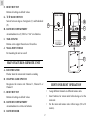
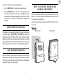
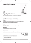
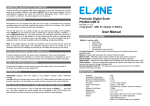
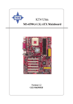
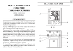
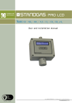
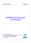
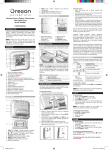
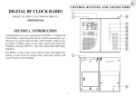
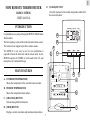
GB
MINI REMOTE THERMOMETER
E. [CLEAR] BUTTON
Clears the memory for the indoor temperature and that for
the selected channel
MODEL: MTR101
USER'S MANUAL
INTRODUCTION
Congratulations on your purchasing the MTR101 Mini Remote
Thermometer.
A
The basic package comes with a main unit and a remote sensor.
The main unit can support up to three remote sensors.
B
F
The MTR101 is very easy to use. No wire installation is
required between the main unit and the remote units. As the
MTR101 operates at 433MHz, it can be used in the U.S. and
most places in Continental Europe.
C
G
MAIN FEATURES
°C
°F
A. OUTDOOR TEMPERATURE
RESET
D
E
J
Shows the temperature of the selected remote channel
B. INDOOR TEMPERATURE
H
Shows the temperature taken indoors
C. [CHANNEL] BUTTON
Selects among different channels
I
D. [MEM] BUTTON
Displays current, maximum and minimum temperatures
1
GB
F. RESET BUTTON
Returns all settings to default values
G. °C/°F SLIDE SWITCH
Selects between degrees Centigrade (C) and Fahrenheit
(F)
B
A
C
H. BATTERY COMPARTMENT
Accommodates two (2) UM-3 or “AA” size batteries
D
I. TABLE STAND
Rotates out to support the unit on a flat surface
J. WALL-MOUNT HOLE
For mounting the unit on a wall
E
MAIN FEATURES: REMOTE UNIT
A. LED INDICATOR
Flashes when the remote unit transmits a reading
B. CHANNEL SLIDE SWITCH
Designates the remote unit Channel 1, Channel 2 or
Channel 3
HINTS FOR BEST OPERATION
C. RESET BUTTON
Returns all settings to default values
•
Assign different channels to different remote units.
•
Insert batteries for remote units before doing so for the
main unit.
•
Set the main and remote units within range (20 to 30
meters).
D. BATTERY COMPARTMENT
Accommodates two AAA-size batteries
E. BATTERY DOOR
2
GB
•
Try different set-ups for best transmission and reception.
•
Position the remote units away from direct sunlight, rain
or snow.
BATTERY INSTALLATION: MAIN UNIT
1. Slide open the battery compartment door.
2. Insert two AA-sized batteries.
BATTERY AND CHANNEL
INSTALLATION: REMOTE UNIT
1. Remove the screws on the battery compartment.
2. Select the channel number on the CHANNEL slide switch.
3. Install 2 alkaline batteries (UM-4 or “AAA” size 1.5V)
strictly according to the polarities shown.
3. Press RESET.
4. Replace the battery compartment door.
4. Replace the battery compartment door and secure its
screws.
Note that once a channel is assigned to a remote unit, you can
only change it by removing the batteries or resetting the unit.
3
GB
GETTING STARTED
Kinetic-wave
Icon
Once batteries are in place for the remote units, they will start
transmitting samplings roughly at 30-second intervals.
Designated
Display
The main unit will also start receiving once batteries are
installed. The temperature of the selected channel will be
displayed on the main display and the indoor temperature on
the secondary display. The main unit will automatically update
its readings at 30-second intervals.
Remote
Display
Channel One
Remote
Display
Channel Two
Remote
Display
Channel Three
To start an automatic scan on all channels, press and hold
CHANNEL for two seconds. The main unit will scan from
one channel to another and back. The reading for individual
channel will be displayed for five seconds. Press any key to
end the automatic scan.
If no signals are received, blanks will be displayed. Press
CHANNEL and MEM simultaneously to enforce an immediate
search. This is useful in synchronizing the transmission and
reception of the remote and main units.
The MTR101 is capable of measuring temperatures within the
-50°C (-58°F) and +70°C (+158°F) range. If the temperature
goes above or below that, the display will show "HHH" or
"LLL".
INDOOR AND OUTDOOR
TEMPERATURES
MAXIMUM AND MINIMUM
TEMPERATURES
The indoor temperature is shown on the secondary display.
As for the remote sites or channels, press CHANNEL
repeatedly to go from one channel to another. The kinetic wave
display on the channel number indicates the reception of that
particular channel is in good order.
The maximum and minimum recorded indoor temperatures and
those of each channel will be automatically stored in memory.
To display them,
1. Press [CHANNEL] to locate the desired channel.
2. Press [MEM] repeatedly to display the current, maximum
(MAX) and minimum (MIN) temperatures. The readings
of the indoor temperatures will also be displayed.
4
GB
To clear the memory of a particular channel,
HOW TO USE THE TABLE STAND
OR WALL MOUNTING
1. Press [CHANNEL] to locate the desired channel.
2. Press [CLEAR]. Note it will also erase the memory for
the indoor temperatures. If you press MEM now, the
maximum and minimum temperatures will have the same
values as the current ones until different readings are
recorded.
Turn the table stand knob out to place the main unit on a flat
surface. Or you can hide the stand and mount the unit on a
wall using the recessed hole.
As for the remote unit, use the provided Velcro ® tape to secure
it in place.
DISCONNECTED SIGNALS
Main unit
Wall-mount
If without obvious reasons the display for a particular channel
goes blank, press [CHANNEL] and [MEM] to enforce an
immediate search. If that fails, check if the remote unit of that
channel is still in place. Make sure the transmission is within
range and path is clear of obstacles and interference. No reading
will be shown if no remote unit is assigned to that channel.
LOW BATTERY WARNING
When it is time to replace batteries, the respective low-battery
indicator will show up when the respective channel is selected.
The battery level of the main unit will be shown on the indoor
temperature when it is running low.
5
Table Stand
GB
Remote unit
PRECAUTIONS
Wall-mount
This unit is engineered to give you years of satisfactory service
if handled carefully.
Velcro ® tape
1. Do not immerse the unit in water.
2. Do not clean the unit with abrasive or corrosive materials.
3. Do not subject the unit to snow or excessive force, shock,
dust, temperature or humidity.
4. Do not tamper with the unit's internal components.
5. Do not mix new and old batteries or batteries of different
specifications
SPECIFICATIONS
Temperature Measurement
THE RESET BUTTON
Main unit
The [RESET] button is used to enhance synchronization of
signals after battery replacement or when the unit is operating
in an unfavorable way or malfunctioning. Use a blunt stylus to
hold down the button. All settings will return to their default
values.
Indoor Temperature measurement
Displayed IN temperature range
: -9.9°C to +70.0°C
Proposed operating range
: -5.0°C to +50.0°C
Temperature resolution
: 0.1°C (0.2°F)
(14.2°F to 158.0°F)
(23.0°F to 122.0°F)
6
GB
Remote Temperature measurement
Remote sensing unit
Displayed OUT temperature range : -50.0°C to +70.0°C
(-58.0°F to 158.0°F)
Proposed operating range
Weight
: -5.0°C to +50.0°C
(23.0°F to 122.0°F)
Temperature resolution
: 0.1°C (0.2°F)
Main unit
: 76 gm (without
battery)
Remote sensing unit
: 67 gm (without
battery)
Dimension
Remote unit
Displayed temperature
: -50.0°C to +70.0°C
Main unit
: 142(L) x 84(W) x
24.5(T) mm
Remote sensing unit
: 92(L) x 60(W) x
21(T)
mm
(-58.0°F to 158.0°F)
Proposed operating range
: -20.0°C to +60.0°C
(-4.0°F to 140.0°F)
Temperature resolution
: 0.1°C (0.2°F)
RF Transmission Frequency
: 433 MHz
No. of Remote unit
: Maximum of 3
RF Transmission Range
: 30 meters
(open area)
Temperature sensing cycle
: around 30 seconds
NOTE ON COMPLIANCE
This product complies with standards and specifications of
BZT, FCC and article number 334 of PTT.
Warning: Changes or modifications to this unit not expressly
approved by the party responsible for compliance could void
the user’s authority to operate the equipment.
Power
Main unit
: use 2 pcs UM-4 or
“AAA”
1.5V
alkaline battery
: use 2 pcs UM-3
or”AA” 1.5V
alkaline battery
NOTE: This equipment has been tested and found to comply
with the limits for a Class B digital device, pursuant to Part 15
of the FCC Rules. These limits are designed to provide
reasonable protection against harmful interference in a
residential installation. This equipment generates, uses and can
7
GB
radiate radio frequency energy and, if not installed and used in
accordance with the instructions, may cause harmful
interference to radio communications.
CAUTION
- The content of this manual is subject to change
without further notice.
However, there is no grarantee that interference will not occur
in a particular installation. If this equipment does cause harmful
interference to radio or television reception, which can be determined by turning the equipment off and on, the user is
encouraged to try to correct the interference by one or more of
the following measures:
- Due to printing limitation, the displays shown in
this manual may differ from the actual display.
- The manufacturer and its suppliers held no
responsibility to you or any other claim arising
by using this product.
1. Reorient or relocate the receiving antenna.
- The contents of this manual may not be
reproduced without the permission of the
manufacturer.
2. Increase the separation between the equipment and receiver.
3. Connect the equipment into an outlet on a circuit different
from that to which the receiver is needed.
4. Consult the dealer of an experienced radio/TV technician
for help.
8