1
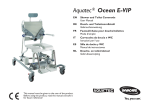
OCEAN VIP
DE
ES
Dusch- und Toilettenrollstuhl
Silla de ducha y WC
Gebrauchsanweisung
Manual de instrucciones
EN
SV
Commode
Dusch- och toalettstol
Operating Instructions
Bruksanvisning
FR
Chaise roulante pour douche/
toilettes
Mode d’emploi
NL
Douche- en toiletrolstoel
Gebruiksaanwijzing
IT
Carrozzina da doccia e da toilette
Istruzioni per l’uso
FI
Suihku- ja wc-pyörätuoli
Käyttöohje
NO
Dusj- og toalettstol
Bruksanvisning
DA
Bruse- og toiletkørestol
Betjeningsvejledning
DE
ES
WICHTIG!
Bitte lesen Sie diese Gebrauchsanweisung aufmerksam durch, bevor Sie das Produkt benutzen. Beachten
Sie alle Hinweise, insbesondere die Sicherheitshinweise, und handeln Sie danach.
EN
¡IMPORTANTE!
Por favor lea este manual de instrucciones atentamente
antes de utilizar el producto. Tenga en cuenta todas las
indicaciones, especialmente las relativas a la seguridad, y sígalas.
SV
IMPORTANT!
Before you use the product, please read these operating instructions carefully. Pay attention to all instructions, especially those regarding safety, and follow them
at all times.
OBSERVERA!
Läs igenom bruksanvisningen noggrant innan produkten används. Beakta och följ alla anvisningar, i synnerhet säkerhetsanvisningarna.
FR
FI
TÄRKEÄÄ!
IMPORTANT !
Veuillez lire attentivement ce mode d’emploi avant d’utiliser le produit. Veuillez respecter toutes les consignes,
notamment les consignes de sécurité, et agir en conséquence.
NL
Lukekaa tämä käyttöohje huolellisesti, ennen kuin
käytätte tuotetta. Noudattakaa kaikkia ohjeita, erityisesti
turvaohjeita, ja toimikaa niiden mukaisesti.
NO
VIKTIG!
BELANGRIJK!
Lees deze gebruiksaanwijzing aandachtig door, voordat
u het product gebruikt. Neem alle instructies in acht,
vooral de veiligheidsinstructies en volg deze op.
IT
Les bruksanvisningen nøye før du tar i bruk produktet.
Følg alle henvisningene, spesielt ang. sikkerhet.
DA
IMPORTANTE!
Si prega di leggere attentamente queste istruzioni per
l’uso prima di utilizzare il prodotto. Attenersi a tutte le indicazioni, in particolar modo a quelle relative alla sicurezza e procedere di conseguenza.
VIGTIGT!
Læs denne betjeningsvejledning opmærksomt igennem, før du anvender produktet. Læg mærke til alle
henvisninger, især sikkerhedshenvisningerne, og overhold dem.
1
2
3
4
5
6
7
8
9
10
11
Contents
1
General instructions
1
1.1
1.2
1.3
1.4
1.5
1.6
General instructions . . . . . . . . . . . . . . . . 10
Introduction . . . . . . . . . . . . . . . . . . . . . . . . 10
Proper use . . . . . . . . . . . . . . . . . . . . . . . . 10
Warranty . . . . . . . . . . . . . . . . . . . . . . . . . . 10
Re-use/Reconditioning . . . . . . . . . . . . . . . 10
Disposal . . . . . . . . . . . . . . . . . . . . . . . . . . 10
CE marking . . . . . . . . . . . . . . . . . . . . . . . . 11
1.1
2
2.1
2.2
Safety instructions . . . . . . . . . . . . . . . . . 11
Warnings and symbols . . . . . . . . . . . . . . . 11
General instructions . . . . . . . . . . . . . . . . . 11
Keep all documents supplied in a safe place.
3
3.1
3.2
Description . . . . . . . . . . . . . . . . . . . . . . . 11
Scope of delivery . . . . . . . . . . . . . . . . . . . 11
Technical data. . . . . . . . . . . . . . . . . . . . . . 11
4
Transport . . . . . . . . . . . . . . . . . . . . . . . . . 11
Do not use the commode outdoors or as a climbing
aid.
5
5.1
5.1.1
5.1.2
5.1.3
Setting up . . . . . . . . . . . . . . . . . . . . . . . . 11
Assembling the commode. . . . . . . . . . . . . 11
Inserting and moving the clips . . . . . . . . . 12
Fitting the backrest . . . . . . . . . . . . . . . . . . 12
Attaching the removable handle
and cable ties . . . . . . . . . . . . . . . . . . . . . . 12
Fitting the footrests . . . . . . . . . . . . . . . . . . 12
Fitting the headrests . . . . . . . . . . . . . . . . . 12
The commode can be used as a commode for standard toilets or with an (optional) sanitary pan.
5.1.4
5.1.5
6
6.1
6.2
6.3
6.12
6.13
Operation . . . . . . . . . . . . . . . . . . . . . . . . . 13
Adjusting the seat height. . . . . . . . . . . . . . 13
Adjusting the height of the footrests . . . . . 13
Adjusting the inclination of the foot
plates . . . . . . . . . . . . . . . . . . . . . . . . . . . . 13
Adjusting the height of the armrests . . . . . 13
Adjusting the backrest cover. . . . . . . . . . . 14
Use . . . . . . . . . . . . . . . . . . . . . . . . . . . . . . 14
Folding the arm rests . . . . . . . . . . . . . . . . 14
Folding the footrests . . . . . . . . . . . . . . . . . 14
Swivelling the seat frame with
backrest . . . . . . . . . . . . . . . . . . . . . . . . . . 15
Locking the position locking device. . . . . . 15
Detaching and attaching the seat
plate . . . . . . . . . . . . . . . . . . . . . . . . . . . . . 15
Removing and attaching the heel loop . . . 15
Troubleshooting . . . . . . . . . . . . . . . . . . . . 16
7
7.1
7.2
7.3
Care and maintenance . . . . . . . . . . . . . . 16
Cleaning . . . . . . . . . . . . . . . . . . . . . . . . . . 16
Maintenance . . . . . . . . . . . . . . . . . . . . . . . 16
Changing the casters . . . . . . . . . . . . . . . . 16
6.4
6.5
6.6
6.7
6.8
6.9
6.10
6.11
10
Introduction
These operating instructions contain information and
instructions regarding the safe and proper use of your
commode.
In the text of these operating instructions, we refer to
figures and individual items within the figures. These
references are shown in brackets.
Example: (3, fig. 2) refers to figure 2, item 3.
1.2
Proper use
The commode is to be used solely as an aid for showering or bathing, going to the toilet or for transfer indoors.
Any other use is prohibited.
1.3
Warranty
The warranty depends on the legal specifications in
the country of destination or on the specifications
made by our sales partners.
In the event of damage, please notify your specialist
dealer or contact one of the addresses printed in these
operating instructions.
The warranty period begins at the delivery date as
shown on the delivery note.
1.4
Re-use/Reconditioning
The product is designed for repeated use. The maximum number of times you can re-use the product depends on its general state and condition.
On reconditioning, always follow the AQUATEC reconditioning and hygiene instructions. These are available
on request from AQUATEC.
1.5
Disposal
Important!
The product does not contain any hazardous
substances.
Always dispose of the individual parts at your local facility according to the material identification labels on
the parts.
Proper and complete disposal can be carried out by
the manufacturer.
EN
1.6
CE marking
The product complies with EU Directive 93/42/EEC for
medical equipment.
3
3.1
2
Safety instructions
2.1
Warnings and symbols
The following warnings and symbols are used in these
operating instructions:
CAUTION!
*
This notice indicates a potential hazard.
Not following these instructions can result in injury or damage.
Important!
This symbol indicates additional instructions,
information or tips.
2.2
General instructions
Lock the brakes in the parked position.
Only use the commode indoors and on even,
flat surfaces.
Description
Scope of delivery
The AQUATEC OCEAN VIP is supplied with the following parts (fig. 2):
1
2
3
4
5
6
7
8
9
Head support
Backrest with cover and armrests
Operating instructions (in plastic bag)
Screws (4 x) for backrest
Cable ties (2 x)
Allen key
Clips (2 x) for footrests (in plastic bag)
Footrests with heel loops (2 x)
Seat frame with seat plate and side sections with
casters
10 Clips (2 x) for height adjustment (inserted from the
inside)
3.2
Technical data
Dimensions
Width
Depth
Height (without head support)
Seat width
Seat depth
Seat height
Min. distance between floor
and holder for the sanitary pan
Weight
Load capacity
576 mm
1,058 mm
1,098 − 1,198 mm
500 mm
452 mm
500/550/600 mm
422 − 522 mm
approx. 21 kg
150 kg
If you detect any malfunction, please contact
your authorised dealer immediately.
The label (fig. 1) provides important technical information.
Do not modify or reconstruct the device.
The label is attached to the inside of the right side section.
4
Never carry out work on the pneumatic
springs. Please contact your authorised
dealer immediately if a pneumatic spring is
damaged or faulty.
Observe the information on the label. Do not
overload the commode.
Transport
You can easily disassemble the commode into its component parts (section 3.1) for transport.
For detailed instructions on how to dismantle the device, please refer to section 5.
5
Setting up
Important!
● Before setting up, inspect all parts for damage during transport.
*
●
This section describes the assembly. Disassembly is carried out in reverse order.
●
During assembly, make sure the parts are
positioned correctly in relation to each other
(fig. 2).
In the text, a picture illustrating the type of risk replaces the asterisk.
EN
11
5.1
Assembling the commode
5.1.1
Inserting and moving the clips
1.
2.
Pull the two clips for height adjustment (10, fig. 2)
from the inside of the seat frame and insert into
the side section from the outside until both lugs (6,
fig. 8) enclose the seat frame tube (2, fig. 8).
Remove both clips for the footrests (7, fig. 2) from
the plastic bag and insert into the guide (8, fig. 6)
of the seat frame (9, fig. 6) until both lugs enclose
the guide.
5.1.2
1.
Fitting the backrest
Lock all casters using the red foot pedals. To do
this, push down the red foot pedal for the casters.
Important!
When folded up, the armrests must face forward.
2.
7.
Fix the wire. To do this, place a cable tie (5, fig. 2
or 2, fig. 5) around the tubular frame (1, fig. 5) and
the wire (3, fig. 5) on the left and right side of the
lower curve of the backrest frame and tighten.
8.
Shorten the projecting ends of the cable ties.
5.1.4
Important!
The assembly procedure is the same for the
right and the left footrests.
Push the footrest (1, fig. 6) and the footplate (4, fig. 6)
inwards into the guide (8, fig. 6) on the seat frame (9,
fig. 6) until the groove (2, fig. 6) catches the pin on the
clip (7, fig. 6). The footrests can no longer be turned to
the sides.
5.1.5
Tighten the backrest on the left and right sides
using two screws on each side (2, fig. 3).
5.1.3
1.
●
Attaching the removable handle and cable
ties
Use the star handle to insert the screw (6, fig. 7) a
little into the bracket (7, fig. 7).
2.
Important!
Feed the wire (1, fig. 4) for activating the pneumatic springs through the gap between the
backrest cover and the belt locks.
Push the bracket with the screw onto the handle
of the backrest (5, fig. 7) from behind in such a
way that the screw engages in the hole of the
backrest’s handle.
3.
Insert the plate (4, fig. 7) into the bracket from the
front in such a way that both lugs of the plate face
down and up and the curved plate side touches
the handle of the backrest.
Unscrew the two cross slotted cheese head
screws (4, fig. 4) from the removable handle (2,
fig. 4) and remove the lower part of the fastening
clamp (5, fig. 4).
Guide the removable handle upwards through the
gap between the backrest cover and the belt locks
(6, fig. 4).
3.
Place the removable handle with the top part of
the fastening clamp onto the handle of the backrest so that the hand lever (3, fig. 4) points to the
right.
Fix the removable handle to the tubular frame
using the bottom part of the fastening clamp and
the two cross slotted cheese head screws. Tighten the screws lightly.
5.
Align the removable handle as shown in fig. 4.
6.
Tighten the two cross slotted cheese head
screws.
12
The headrest pad (10, fig. 7) can be removed and replaced by other pad shapes
(optional). To remove it, loosen the retaining bolts (9, fig 7).
1.
2.
4.
Fitting the headrests
Important!
● To adapt it to the user, the grab handle can
be fitted with the curve facing the front or
the back.
Push the backrest (1, fig. 3) from behind onto the
pin on the seat frame (3, fig. 3) until the collar of
the backrest touches the seat frame tube.
Important!
Tighten the screws using the Allen key supplied.
3.
Fitting the footrests
Important!
On inserting the retainer, the curved side of the
plate must rest entirely on the handle of the
backrest.
4.
Push the grab handle (3, fig. 7) from above into
the recesses of the bracket.
5.
Use the star handle to tighten the screw (6, fig. 7)
until the grab handle is fixed.
6.
Push the pad (10, fig. 7) and the pad holder (2,
fig. 7) into the holder on the grab handle (8, fig. 7).
7.
Use the star handle to tighten the upper screw (1,
fig. 7) until the pad holder is fixed.
EN
6
6.1
Operation
6.4
Important!
● The height of the armrests must be adjusted to suit the user.
Adjusting the seat height
Important!
● The seat height must be adjusted to suit the
user. As a rule, the seat height is correctly
adjusted when the user is sitting on the
commode and both feet touch the ground.
●
●
The seat height must be adjusted on both
sides simultaneously. To make adjustments, a second person is required to help.
Do not adjust the seat height of the commode when someone is sitting on it.
Adjusting the height of the armrests
●
The height of the armrests must be adjusted by the same amount on both sides.
●
The height of the right and left armrest is
adjusted in the same way.
1.
Open the belt lock of the belt inside the backrest
frame at the backrest cover.
2.
Open the belt lock of the belt above the armrests
at the backrest cover (1, fig. 9).
3.
Feed this belt along the backrest frame and close
again.
1.
Slightly raise the commode at the seat frame.
2.
Take out both clips (5, fig. 8).
3.
To adjust the seat height, pull the seat frame out
of the side section (1, fig. 8) or push it in.
4.
Align the clip recesses (3, fig. 8) at the side section with a hole on the seat frame (4, fig. 8).
Unscrew the screws (3, fig. 9) of the armrest holder (4, fig. 9) using the supplied Allen key.
5.
Remove the fastening clamp (2, fig. 9) with the
nuts from the inside of the backrest frame.
6.
Remove the armrest holder (4, fig. 9) with the
armrest and move upwards.
4.
5.
6.2
Push both clips from the outside into the side section until the two lugs (6, fig. 8) enclose the seat
frame tube (2, fig. 8).
Important!
The nuts are inserted loosely in the fastening
clamp and can fall out.
Important!
The small hole is for fixing the fastening clamp.
Adjusting the height of the footrests
1.
Pull up the footrest (1, fig. 6) slightly.
7.
2.
Pull out the clip (7, fig. 6) and put it in again at the
required position. Pull out the footrest slightly further if necessary.
Insert the screws into the armrest holder and
guide into the holes in the backrest frame.
8.
Replace the nuts in the fastening clamp if necessary.
3.
Push down the footrest until the groove (2, fig. 6)
catches the pin of the clip (7, fig. 6).
9.
4.
Set the other footrest to the same height as described.
Place the fastening clamp onto the backrest frame
so that the fixing of the fastening clamp engages
with the small hole.
6.3
Adjusting the inclination of the foot
plates
Important!
● The inclination of the foot plates can be adjusted infinitely variably.
●
The right and left foot plates must be adjusted in the same way.
1.
Loosen the Allen screw (3, fig. 6) on the foot plate
using a size 4 Allen key.
2.
Turn the foot plate (4, fig. 6) to the desired position.
3.
Tighten the Allen screw again.
EN
10. Insert the screws into the nuts and tighten.
11. Guide the belt of the backrest cover around the
back rest frame, close it and then tighten all the
belts.
Follow the same procedure to adjust the armrests to
the lower position.
Important!
Open the belt below the armrest and feed it
through the backrest frame if you are adjusting
the armrest to the lower position.
13
6.5
Adjusting the backrest cover
CAUTION!
Important!
● The lower seam (5, fig. 10) of the backrest
cover must always be below the distance
piece (6, fig. 10) of the backrest frame (4,
fig. 10).
Tipping over
●
Push the footrests to the sides or fold up
the foot plates before getting into or out
of the chair.
●
To attach accessories, the second belt lock
can be opened from above and the backrest cover can be passed by the backrest
frame on the inside at this point (3, fig. 10).
●
Swivel the front casters so that the lock
is pointing forwards before getting into or
out of the chair.
●
Do not stand on the footrests.
●
At least three belts must always be passed
by the backrest frame (on the outside) and
their belt locks must be closed.
●
Only drive the user on the commode
when the seat frame and backrest are
fixed in the upright position.
●
Never remove the pneumatic springs.
The backrest tension can be individually adjusted.
Tensioning:
Risk of breakage during transport
Tighten the belts (1, fig. 10) of the backrest cover.
Loosening:
1.
Open the belt locks (2, fig. 10) by pressing the
lugs (arrow, fig. 10).
2.
Push the belt back through the lock.
3.
Close the belt locks.
4.
Slightly tension the belt.
6.7
●
Only lift the commode by the sides when
someone is sitting in it.
●
Use only the handle on the backrest to
steer or push the commode, never the
head support.
Folding the arm rests
CAUTION!
6.6
Use
Risk of catching due to folding mechanism
When using the commode, observe the following safety rules:
●
When folding down the armrests, do not
reach into the joint, and make sure that
no parts become jammed.
●
When folding up the armrests, do not
reach between the armrest and the
backrest.
CAUTION!
●
Seat surface may slip if loose
Check whether the seat surface is firmly
secured to the seat frame before use.
●
Slipping caused by the chair rolling
6.8
Lock the casters using the red foot pedals before getting into or out of the chair.
Position for getting in and out:
1.
Push the footrest slightly upwards along the guide
until the groove (2, fig. 6) no longer catches the
pin of the clip (7, fig. 6).
2.
Fold the footrest to the side.
Rolling away
Lock the casters with the red foot pedals in
parked position.
Folding the footrests
Driving position:
CAUTION!
Loose footrests can be dangerous
Fix the footrests in the driving position.
14
1.
Turn the footrests inwards.
2.
Push down the footrest until the groove (2, fig. 6)
catches the pin of the clip (7, fig. 6).
EN
6.9
Swivelling the seat frame with backrest
6.11
Important!
● Only use the removable handle and only
swivel the seat frame with backrest if a user
is sitting on the commode.
Detaching:
●
2.
3.
Pull up the seat plate on both sides.
Attaching:
CAUTION!
On swiveling the seat frame with backrest,
pull the backrest backwards or forwards using the handle.
Risk of catching
Do not reach between the seat surface and
the seat frame when pressing down the
seat plate.
●
Never reach into the area between the seat
frame with backrest and the front tubular
frame between the side sections when
swivelling.
1.
●
Do not drive when the seat frame of the
backrest is swivelled.
Place the seat plate on the seat frame with the
hole at the front (fig. 2).
2.
Push the seat plate as far back as it will go.
3.
Using the palm of your hand, push the sides of the
seat plate down, and then the front and the back,
until the seat plate snaps into the seat frame.
The seat frame can be tilted approx. 35° backwards together with the backrest.
1.
Pull the removable handle (4, fig. 11) and hold it in
this position. The distributor (3, fig. 11) is used to
release the blocking of the pneumatic springs (2,
fig. 11).
6.12
1.
Press the seat frame (1, fig. 11) at the handle of
the backrest (5, fig. 11) backwards or forwards together with the backrest. The pneumatic springs
(2, fig. 11) are extended (fig. 11) or retracted.
Release the removable handle. The seat frame is
fixed at the currently set inclination.
Proceed as follows to swivel the seat frame with backrest forward if it is swivelled backwards without a user:
1.
Stand next to the commode.
2.
Pull the removable handle with one hand and
keep in this position.
3.
Press the seat frame with backrest down by pushing the middle of the seat surface with your other
hand.
4.
Release the removable handle once the seat
frame with backrest is swivelled forwards. The
seat frame is now fixed in this position.
6.10
Detaching and attaching the seat plate
Removing and attaching the heel loop
Open the velcro fastening at the heel loop (6,
fig. 6).
Important!
When the bolt is unscrewed, the nut below
may fall out.
2.
Unscrew the bolt (5, fig. 6).
3.
Take off the screw with the spacer, and the nut underneath the foot plate.
4.
Pull the heel loop off the spacer.
The heel loop can be fitted in the reverse order.
Important!
The velcro fastening of the heel loop should be
inside when fitted.
Locking the position locking device
Important!
The position locking device only locks in position if the wheel is in forward position.
Lock the locking device at the caster with the blue foot
pedal. The caster is fixed in forward position.
EN
15
6.13
Troubleshooting
CAUTION!
Problem
Possible causes
Difficulty in
adjusting the seat
height
Dirt between the
Disassemble the
seat frame and the commode into its
side section
component parts
and clean it
thoroughly
The casters are
difficult or
impossible to turn
Remedy
Dirt between the
Thoroughly clean
fork and the wheel the casters
Difficulty pushing Dirt in the guides
the footrests to the
side
Remove the
footrests and
thoroughly clean
them
The seat frame
with backrest
cannot be
swiveled
Nut (6, fig. 11)
loosened on the
distributor (3,
fig. 11)
Tighten the nut
The pneumatic is
faulty
Contact the
authorised dealer
7
Burns
Let the commode cool down before touching it.
In clinics, in addition to the cleaning operations described above, the commode should be cleaned at
regular intervals at 85 °C for 3 minutes in the autoclave.
7.2
Maintenance
The commode is maintenance-free provided you follow the care instructions described above.
7.3
Changing the casters
CAUTION!
Only authorised dealers may change the
casters.
Care and maintenance
Important!
● Hygiene is especially important as regards
the toilet. Regularly clean the commode
and keep it clean.
●
7.1
This product can be disinfected. Choose
the disinfectant in accordance with
AQUATEC care guidelines. These are
available on request from AQUATEC.
Cleaning
Important!
● Do not use abrasive cleaning agents.
●
Do not detach the holders for the accessories.
1.
Take off any fitted accessories.
2.
Pull the footrests out of the guides.
3.
Take off the seat plate and the backrest cover.
4.
Wash the individual parts with commercial detergents (e.g. all purpose cleaning agents) using a
cloth or brush.
5.
Rinse the parts under warm water.
6.
Dry the parts with a cloth.
7.
Reassemble the commode.
16
EN