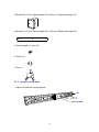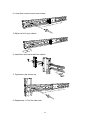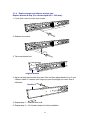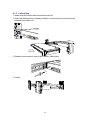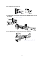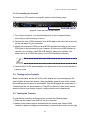
1
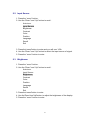
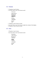
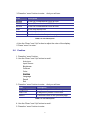
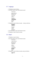
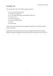
Drawer KVM Console With 17” LCD DKVM-1700 User’s Manual Version 1.0 1 Copyright Copyright (C) 2008 PLANET Technology Corp. All rights reserved. The products and programs described in this User’s Manual are licensed products of PLANET Technology, This User’s Manual contains proprietary information protected by copyright, and this User’s Manual and all accompanying hardware, software, and documentation are copyrighted. No part of this User’s Manual may be copied, photocopied, reproduced, translated, or reduced to any electronic medium or machine-readable form by any means by electronic or mechanical. Including photocopying, recording, or information storage and retrieval systems, for any purpose other than the purchaser's personal use, and without the prior express written permission of PLANET Technology. Disclaimer PLANET Technology does not warrant that the hardware will work properly in all environments and applications, and makes no warranty and representation, either implied or expressed, with respect to the quality, performance, merchantability, or fitness for a particular purpose. PLANET has made every effort to ensure that this User’s Manual is accurate; PLANET disclaims liability for any inaccuracies or omissions that may have occurred. Information in this User’s Manual is subject to change without notice and does not represent a commitment on the part of PLANET. PLANET assumes no responsibility for any inaccuracies that may be contained in this User’s Manual. PLANET makes no commitment to update or keep current the information in this User’s Manual, and reserves the right to make improvements to this User’s Manual and/or to the products described in this User’s Manual, at any time without notice. If you find information in this manual that is incorrect, misleading, or incomplete, we would appreciate your comments and suggestions. FCC This equipment has been tested and found to comply with Part 15 of the FCC Rules. Operation is subject to the following two conditions: (1) This device may not cause harmful interference (2) This device must accept any interference received. Including interference that may cause undesired operation. CE This equipment is in compliance with the requirements of the following regulations: EN 55 022: CLASS B WEEE regulation To avoid the potential effects on the environment and human health as a result of the presence of hazardous substances in electrical and electronic equipment, end users of electrical and electronic equipment should understand the meaning of the crossed-out wheeled bin symbol. Do not dispose of WEEE as unsorted municipal waste and have to collect such WEEE separately. Trademarks The PLANET logo is a trademark of PLANET Technology. This documentation may refer to numerous hardware and software products by their trade names. In most, if not all cases, these designations are claimed as trademarks or registered trademarks by their respective companies. Revision User’s Manual for PLANET Drawer KVM Console with 17” LCD Model: DKVM-1700 Rev: 1.0 (June, 2008) Part No. EM-DKVM1700 2 Packing List The complete package consists of: One 1U 19” rack mount drawer KVM console Two rails with front and rear bracket Two brackets A. (Needed for rack depth 828 ~ 1000 mm) Two brackets B. (Needed for rack depth 504 ~ 614 mm) Two brackets C. (Needed for rack depth 504 ~ 614 mm) One 1.8 m KVM cable. (HDDB-15 / VGA + PS/2 x 2) One AC to DC power adapter One user’s manual CD One quick installation guide Two keys Six flat screws. (for rail mount to console body) Eight screws. (for replace long bracket A) Check to make sure that the unit was not damaged in shipping. If you encounter a problem, contact your dealer. Please read this manual thoroughly, and follow the installation and operation procedures carefully to prevent any damage to the product, and / or any of the devices that connect to it. I Safety Instructions 1. Please disconnect this equipment from AC outlet before cleaning. Don’t use liquid or sprayed detergent for cleaning. Use moisture sheet or clothe for cleaning. 2. For pluggable equipment, the socked-outlet shall be installed near the equipment and shall be easily accessible. 3. Please keep this equipment from humidity. 4. Lay this equipment on a reliable surface when install. A drop or fall could cause injury. 5. Do not leave this equipment in an environment unconditioned, storage temperature above 60 0C, it may damage the equipment. 6. The opening on the enclosure is for air convection hence the equipment from overheating. DO NOT COVER THE OPENING. 7. Make sure the voltage of the power source connect the equipment to the power outlet. 8. Please keep the power cord such a way that people can not step on it. Do not place anything over power cord. The power cord must rate for the voltage and current marked on the product’s electrical ratings label. The voltage and current rating of the cord should be greater than the voltage and the current rating marked on the product. 9. All cautions and warning on the equipment should be noted. 10. If the equipment is not in use for long time, disconnect the equipment from mains to avoid being damaged by transient over-voltage. 11. Never pour any liquid into ventilation openings; this could cause fire or electrical shock. 12. Never open the equipment. For safety reason, qualified service personnel should only open the equipment. 13. If one of the following situations arises, get the equipment checked by service personnel. The Power Cord or plug is damaged. Liquid has penetrated into the equipment. The equipment has been exposed to moisture. The equipment has not worked well or you can not get it work according to User’s Manual. The equipment has dropped and damaged. If the equipment has obvious signs or breakage. II Index of Contents Packing List ................................................................................................................................................. I Safety Instructions .....................................................................................................................................II Index of Contents..................................................................................................................................... III 1. General Information................................................................................................................... 1 1.1 Feature....................................................................................................................................... 1 1.2 Benefits ...................................................................................................................................... 2 1.3 Advantage ................................................................................................................................. 2 1.4 Product Specification ............................................................................................................... 3 2. Panel Controls and OSD Function................................................................................................... 4 2.1 Auto Tune .................................................................................................................................. 4 2.2 Input Source.............................................................................................................................. 5 2.3 Brightness.................................................................................................................................. 5 2.4 Contrast ..................................................................................................................................... 6 2.5 Color........................................................................................................................................... 6 2.6 Position ...................................................................................................................................... 7 2.7 Language................................................................................................................................... 8 2.8 Recall ......................................................................................................................................... 8 2.9 Exit.............................................................................................................................................. 9 2.10 Power Indicator....................................................................................................................... 9 3. Installation ......................................................................................................................................... 10 3.1 Install DKVM-1700 into Cabinet ........................................................................................... 10 3.1.1 Notes.............................................................................................................................10 3.1.2 Hardware Kits Contents .............................................................................................10 3.1.3 Install Console Step....................................................................................................11 3.1.4 Replace longer and shorter bracket step ..............................................................14 3.1.5 Unload Step .................................................................................................................16 3.2 Install Modular KVM Switch Step......................................................................................... 18 3.2.1 Hardware Kits Contents .............................................................................................18 3.2.2 Install Modular KVM Switch Step..............................................................................18 3.3 Installing the Video Card and Video Driver ........................................................................ 19 3.3.1 Configuring the Display Settings .................................................................................19 3.3.2 Connecting the Console................................................................................................21 3.4 Turning on the Console ..................................................................................................... 21 3.5 Testing the Console ........................................................................................................... 21 III 1. General Information DKVM-1700 is the drawer KVM with single-rail console design offering industrial level input solution, which optimizes your space utilization by controlling your systems in just 1U space on the rack. The separate rail design helps users install the KVM console more easily. You don’t have to prop the heavy console during the installation but just lock the rails into the rack and then pull the KVM console into the rails. With modular design, you can easily integrate different KVM modules to fit your control system. The DKVM-1700 provides the flexibility for users to select which KVM module they need for connection. With the PS/2 KVM Switch module, you can use PS/2 cable either to control multiple PCs or servers or connect PLANET KVM-800 / KVM-1600 up to 8 tiers. In this chain, you can control up to 128 PCs or servers with the same console. The 8/16-port Combo-Free KVM Switch module is also available to fit to most servers that doesn’t supprot PS/2 interface. With the Combo-Free KVM Switch module, users can use PS/2 or USB type cables to control multiple PCs or servers without any concern. The KVM switch modules are loaded with rich features, such as one local console port, Daisy chain capability, On Screen Display (OSD) menu, Password security, Searching PC server name, Hot key control, Push button and Auto-Scan control, complete keyboard and mouse emulation for simultaneously PC boot-up processes. 1.1 Feature Easy to install, single rail design. Support Sun native resolution Support 17 various keyboard languages (increasing) Bright Active TFT display OSD function for LCD display and KVM switch Durable keyboard with touchpad Panel protected by tempered glass Integration with 4 models of KVM switches Supports PS/2 and Combo-Free KVM switch module 1 1.2 Benefits 1. Cost effective solution : With our unique design and all the options, you can easily suffice the demand for your customer at reasonable cost. 2. Time to serve your customer : With the modular KVM, you can easily turn single port console into 8 / 16 ports console to serve your customer well. 3. Easy to maintain : Once the defective comes from the KVM switch, you can just swap the KVM switch module without asking your customer to send the whole console back to you. 4. Save freight cost : Since you have to keep only 4 models of KVM switch modules and generate new models by yourself, you can ship all the goods by sea instead of by air. In case, you run out of the KVM switch stock, it is much cheaper to ship the KVM switch modules by air. 1.3 Advantage Easy to install: With the unique separate rail design. One man can install the KVM console easily. In case you need to maintain the console, you can easily uninstall without effecting the server above or below. Modular KVM switches: The user can use DKVM-1700 as single port console or through some simple action and few screws to be 8/16 ports KVM switch. Various keyboard language support: to fit the demand of each individual countries. 2 1.4 Product Specification Dimension 470.1 x 447.5 x 44 mm / 18.5 x 17.6 x 1.7 inches Package Dimension 606 x 551.5 x 230 mm / 23.9 x 21.7 x 9.0 inches Net Weight 13 Kg / 28.7 lbs Gross Weight 20.5 Kg / 45.2 lbs Display Size 17 inches Panel Type Active Matrix TFT LCD Resolution Capabilities Maximum Resolution up to 1280 x 1024 (SXGA) Pixel Pitch Supports 0.264 mm x 0.264 mm Viewing Angle (CR>10) Right-Left view 60° ~ 70°(Typ) Up-Down View 45° ~ 60°(Typ) Contrast Ratio 450 : 1 Brightness White 250 cd/m2 Back Light Four Lamps for Back Light Supported Colors 16.7M Colors (8-bit with FRC) Response Time Rising Time 2 ms, Decay Time 14 ms Operating System Dos, Windows (3.1, 9x, 2000, NT4, ME, XP, 2003 Server) Linux, Novell 3.12-6, HP UX, SUN Multi Platform Support PS/2 and USB System Cables VGA + PS/2 x 2 or VGA + USB x 1 cable Keyboard Mouse 106 key PS/2 keyboard with touch pad Sync 45 ~ 80 KHz Power Source 100 ~ 240 VAC input Power Consumption 25W, 19.05W for Panel Temperature Operate 0 ~ 50°C / 32 ~ 122°F Storage -20 ~ 60°C / -4 ~ 140°F Humidity 10% ~ 90% RH Chassis Construction Heavy duty steel materials Keyboard Language USA, UK, German, French, Spanish, Italian, Portuguese, Dutch, Swiss, Belgium, Swedish, Norwegian, Danish, Japan, Taiwan, Russian, Hebrew Certification CE / FCC, UL / CUL / C-Tick, GOST 3 2. Panel Controls and OSD Function Controls Description Soft power on/off button. Adjacent LED is lit when on. Auto Auto-synchronize and scale down display to any valid factory preset timings. Press to scroll the function you want to adjust. Press to scroll the function you want to adjust. Menu To access the main menu. This button also acts as the “Enter” button. Table 2-1. Panel Controls Figure 2-1. OSD Control Bar 2.1 Auto Tune Press the “auto tune” button. The panel will adjust the display size automatically and also tune the panel to its best condition. 4 2.2 Input Source 1. Press the “menu” button. 2. Use the “Down” and “Up” button to scroll. Auto tune. Input Source Brightness Contrast Color Position Language Recall Exit 3. Press the“menu”button to enter,and you will see: VGA 4. Use the “Down” and “Up” button to select the input source of signal. 5. Press the “menu” button to enter 2.3 Brightness 1. Press the “menu” button. 2. Use the “Down” and “Up” button to scroll. Auto tune. Input Source Brightness Contrast Color Position Language Recall Exit 3. Press the“menu”button to enter. 4. Use the“Down”and“Up”button to adjust the brightness of the display. 5. Press the “menu” button to enter. 5 2.4 Contrast 1. Press the “menu” button. 2. Use the “Down” and “Up” button to scroll. Auto tune. Input Source Brightness Contrast Color Position Language Recall Exit 1. Press the “menu” button to enter. 2. Use the “Down” and “Up” button to adjust the contrast of the display. 3. Press the “menu” button to enter. 2.5 Color 1. Press the “menu” button. 2. Use the “Down” and “Up” button to scroll. Auto tune. Input Source Brightness Contrast Color Position Language Recall Exit 6 3. Press the “menu” button to enter. And you will see: Icon Description 9300°K To set CIE coordinates at 9300°K color 7500°K To set CIE coordinates at 7500°K color 6500°K To set CIE coordinates at 6500°K color User To set user defined CIE Auto color To auto adjust color Return To exit and return to the previous page Table 2-2. Icon Description 4. Use the “Down” and “Up” button to adjust the color of the display. 5. Press “menu” to enter. 2.6 Position 1. Press the “menu” button. 2. Use the “Down” and “Up” button to scroll. Auto tune. Input Source Brightness Contrast Color Position Language Recall Exit 3. Press the “menu” button to enter. And you will see: Icon Description Image Pos To adjust the position of the image. OSD Pos To adjust the position of the OSD. Return To exit and return to the previous page Table 2-3. Icon Description 4. Use the “Down” and “Up” button to scroll. 5. Press the “menu” button to enter. 7 2.7 Language 1. Press the “menu” button. 2. Use the “Down” and “Up” button to scroll. Auto tune. Input Source Brightness Contrast Color Position Language Recall Exit 3. Press the “menu” button to enter. And you will see: English German French Italian Spanish 4. Use the “Down” and “Up” button to scroll. 5. Press the “menu” button to enter. 2.8 Recall 1. Press the “menu” button. 2. Use the “Down” and “Up” button to scroll. Auto tune. Input Source Brightness Contrast Color Position Language Recall Exit 3. Press the “menu” button to enter, and you will see: Yes/ No 8 4. Select “Yes” button then ‘Menu” button to recall the factory setting. Select “No “ to return to the previous page. 2.9 Exit Press the “exit” button to quit OSD menu. 2.10 Power Indicator GREEN RED RED RED ON STANDBY SUSPEND OFF OSD – On Screen Display 9 3. Installation 3.1 Install DKVM-1700 into Cabinet 3.1.1 Notes 1. Please check all peripherals according the list before installation. To make sure that the whole unit was not damaged and lost during shipping process. If you encounter any problem, please contact your dealer. 2. Before installation, make sure all peripherals and computer have been turned off. 3. The standard brackets are for 614 ~ 1000 mm (distance means front bracket to rear bracket) cabinet, contact your dealer if you need more longer rear brackets. 4. If your cabinet depth is 828 ~ 1000 mm, please refer “Replace bracket A step”. And If your cabinet depth is 504 ~ 614 mm, please refer “Replace bracket B and bracket C step”. 5. Reliable earthing of rack-mounted equipment should be maintained. Particular attention should be given to supply connections other than direct connections to the branch circuit. 3.1.2 Hardware Kits Contents 1. Rail with front and rear bracket x 2 (Please identify the brackets. Right and left sides are different. For cabinet depth 614 ~ 828 mm) 2. Bracket A x 2 (For cabinet depth 828~1000 mm. Please refer page 21) 10 3. Bracket B x 2 (For cabinet depth 504 ~614 mm. Please refer page 22) 4. Bracket C x 2 (For cabinet depth 504 ~614 mm. Please refer page 22) 5. Screw (length = 6 mm) x 6 6. Screw x 8 7. Key x 2 3.1.3 Install Console Step 1. Adjust rail until two screws appear. rail two screws 11 2. Loose (Not remove) seven rear screws. 3. Adjust rail to fit your cabinet 4. Install front and rear bracket on cabinet. 5. Tight seven rear screws up. 6. Repeat step 1~5 for the other side. 12 7. Push console into rails. (Be careful rear box loose when take out console from carton.) 8. Unlock and pull rail–lock switch (left and right at the same time) then push console to the end. lock unlock rail-lock switch 9. Install three screws (length = 6 mm) in rear of the console. (Both sides) 10. Finish installation as below. 13 3.1.4 Replace longer and shorter bracket step Replace bracket A step (For cabinet depth 828 ~ 1000 mm): 1. Loose (Not remove) seven rear screws. 2. Release six screws. 3. Take rear bracket out. original bracket 4. Adjust rail and input bracket A to rear of the rail then adjust bracket A to fit your cabinet. Install 2~3 screws (don’t tight-up) upon the length you need. One is forbidden. bracket A 4. Repeat step 1 ~ 4 for the other side. 5. Repeat step 3 ~ 10 of install console to finish installation. 14 Replace bracket B and C step (For cabinet depth is 504 ~ 614 mm): 1. Remove seven rear screws. 2. Take two original brackets out. original bracket original bracket 3. Input bracket B to rear of the rail. bracket B 4. Install four screws (don’t tight-up) to combine rail, bracket B and bracket C. bracket C bracket B 5. Repeat step 1 ~ 4 for the other side. 6. Repeat step 3 ~ 10 of install console to finish installation. 15 3.1.5 Unload Step 1. Make sure the console has locked and turned off. 2. When the KVM module is already installed. Loose two thumb screws and pull modular KVM switch out . 2. Release three screws in rear of the console. (Both sides) 3. Unlock. 16 4. Pull console out until console lock. 5. Pull rail-release switch and pull console out.(Both sides. Be careful when pull out console.) rail-release switch 5. Push rail-lock switch on the rail and push rail back.(Both sides) rail-lock switch on the rail 17 3.2 Install Modular KVM Switch Step 3.2.1 Hardware Kits Contents 1. Bracket with thumb screw x 2 2. Screw (length = 6 mm) x 4 3.2.2 Install Modular KVM Switch Step 1. Install two screws (length = 6 mm) to combine bracket and KVM switch. (Both sides) 2. Push KVM switch into the rails from rear of cabinet. plastic rail of KVM switch rear view of rail 18 3. Tight thumb screw of bracket up to fix KVM switch in console and finish installation. (Both sides) 3.3 Installing the Video Card and Video Driver Before connecting the LCD console, make sure your computer has a video card already installed for the monitor. After you connect the console, install the video software driver. The video driver is supplied by the video card manufacturer and may be found on the CD-ROM that came with your computer. If you need information on installing a video card or video driver, refer to the manual that came with your video card. 3.3.1 Configuring the Display Settings After connecting the console and turning on your computer, you may need to configure one or more of the following display settings: Display mode (also called desktop area or video resolution) Refresh rate (also called vertical scan rate or vertical sync) Color depth (also called color palette or number of colors) Each video card has several controls that let you adjust the display settings. However, the software and driver for each video card is unique. In most cases, you adjust these settings by using a program or utility provided by the manufacturer of the video card. Most video cards use the Windows Display Properties control panel to configure the display. To open the Windows Display Properties, click the right mouse button in a blank area of the Windows desktop and then select Properties. The Settings tab usually lets you change the Color Palette and the Desktop Area (x by y pixel resolution). Some video cards integrate additional features into the Windows Display Properties control panel to give you an exceptional setup that is flexible and easy to use. For example, the control panel may include an Advanced Properties button, an Adjustment tab, or a Refresh tab for changing other settings. Other video cards have 19 a separate utility for setting display properties. Whenever you change the resolution, color, or refresh rate, the image size, position, or shape may change. This behavior is normal. You can readjust the image using the monitor on-screen controls. For more information on the monitor on-screen controls, refer to Chapter 2. For more information on configuring the display settings, refer to the manual that came with your video card. 20 Unicorn series User’s Manual 3.3.2 Connecting the Console To connect an LCD console to a computer, perform the following steps PS/2-USB switch Figure 3-1. The rear view of LCD console 1. Turn off your computer. You should always turn off your computer before connecting or disconnecting a device. 2. Connect the video (VGA) connector of the KVM cable to the video card connector on the rear panel of your computer. 3. Identify and connect the PS/2 mouse and PS/2 keyboard connector to the correct PS/2 ports on the rear panel of your computer. Or you can use USB interface to connect your computer. (Use PS/2-USB switch to select your interface. The switch has to be on PS/2 side when you use PS/2 interface connector.) Please don't plug PS/2 and USB cables at the same time 4. Connect the AC to DC power adapter to the power inlet on the console and then to a power outlet. 3.4 Turning on the Console Make sure all cables and the AC to DC power adapter are connected properly. Be sure to tighten all connector screws. Using two hands, grasp the rear of the console, lift the tab and pull the panel up and forward. This will disengage the momentary on / off switch and the unit should power on. The LED on the left or under of the monitor panel should turn from orange to green, verifying that the unit is operational. 3.5 Testing the Console To test that the console is working properly, perform the following steps: 1. Power up the console, and then turn on your computer. 2. Make sure the video image is centered within the screen area. Use the OSD controls to adjust the image (see note below) or press the Auto button on the right 21 Unicorn series User’s Manual hand side of the monitor. If the unit does not power up when the panel is pulled up, try pushing the soft power on/off button on the left or under side of the monitor panel to power up the unit. You can adjust the horizontal and vertical position, contrast, and brightness to better suit your video card and your personal preference. Refer to Chapter 2 for more information on using the on-screen menu to adjust the video display. Before you begin, make sure that powers to all the devices you will be connecting up have been turned off. To prevent damage to your installation due to ground potential difference, make sure that all the devices on the installation are properly grounded. Consult your direct vendor for any technical issues if necessary. 22