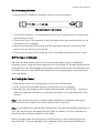
1
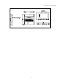
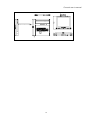
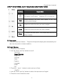
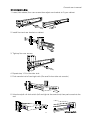
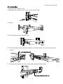
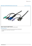
Console user’s manual PACKING LIST The complete KSR-11501/11701/11901 package consists of: z One 1U 19” rack mount console z Two cabinet mounting kits z One 1.8M cable( PS/2 mouse, PS/2 keyboard, DB15 VGA) z One power cord z One user manual VCD z One quick installation guide z Two key z Six flat screws Check to make sure that the unit was not damaged in shipping. If you encounter a problem, contact your dealer. Please read this manual thoroughly, and follow the installation and operation procedures carefully to prevent any damage to the product, and/or any of the devices that connect to it. 1 Console user’s manual SAFETY INSTRUCTIONS 1. Please read these safety instructions carefully. 2. Please keep this User’s Manual for later reference. 3. Please disconnect this equipment from AC outlet before cleaning. Don’t use liquid or sprayed detergent for cleaning. Use moisture sheet or clothe for cleaning. 4. For pluggable equipment, the socked-outlet shall be installed near the equipment and shall be easily accessible. 5. Please keep this equipment from humidity. 6. Lay this equipment on a reliable surface when install. A drop or fall could cause injury. 7. Do not leave this equipment in an environment unconditioned, storage temperature above 600 C, it may damage the equipment. 8. The opening on the enclosure is for air convection hence the equipment from overheating. DO NOT COVER THE OPENING. 9. Make sure the voltage of the power source connect the equipment to the power outlet. 10. Please keep the power cord such a way that people can not step on it. Do not place anything over power cord. The power cord must rate for the voltage and current marked on the product’s electrical ratings label. The voltage and current rating of the cord should be greater than the voltage and the current rating marked on the product. 11. All cautions and warning on the equipment should be noted. 12. If the equipment is not in use for long time, disconnect the equipment from mains to avoid being damaged by transient over-voltage. 13. Never pour any liquid into ventilation openings; this could cause fire or electrical shock. 14. Never open the equipment. For safety reason, qualified service personnel should only open the equipment. 15. If one of the following situations arises, get the equipment checked by service personnel. z The Power Cord or plug is damaged. z Liquid has penetrated into the equipment. z The equipment has been exposed to moisture. z The equipment has not worked well or you can not get it work according to User’s Manual. z The equipment has dropped and damaged. z If the equipment has obvious signs or breakage. 2 Console user’s manual INDEX OF CONTENTS PACKING LIST ............................................................................................................. 1 SAFETY INSTRUCTIONS ............................................................................................. 2 INDEX OF CONTENTS................................................................................................... 3 CHAPTER 1 GENERAL INFORMATION ......................................................................... 4 1.1 Overview .............................................................................................................. 4 1.2 Product Specification............................................................................................ 5 1.2.1 KSR-11501 Specification ............................................................................ 5 1.2.2 KSR-11701 Specification ................................................................................7 1.2.3 KSR-11901 Specification ................................................................................9 CHAPTER 2 PANEL CONTROLS AND OSD FUNCTIONS .............................................11 2.1 Auto tune ........................................................................................................ 11 2.2 Input Source..................................................................................................... 11 2.3 Brightness ........................................................................................................12 2.4 Contrast ...........................................................................................................12 2.5 Color ................................................................................................................12 2.6 Position ............................................................................................................13 2.7 Language..........................................................................................................13 2.8 Recall ...............................................................................................................14 2.9 Exit ...................................................................................................................14 2.10 Power Indicator .................................................................................................14 CHAPTER 3 INSTALLATION.........................................................................................16 3.1 Install Console to Cabinet ....................................................................................16 3.1.1 Notes ..............................................................................................................16 3.1.2 Hardware Kits Contents.................................................................................16 3.1.3 Installation Step .............................................................................................16 3.1.4 Replace Longer Bracket Step ........................................................................18 3.1.5 Unload Step ...................................................................................................19 3.2 Installing the Video Card and Video Driver...........................................................20 3.2.1 Configuring the Display Settings ..................................................................20 3.2.2 Connecting the Drawer .............................................................................21 3.3 Turning on the Drawer........................................................................................21 3.4 Testing the Drawer .............................................................................................21 3 Console user’s manual CHAPTER 1 GENERAL INFORMATION 1.1 Overview The KVM Console is an ideal solution for network administration with multiple servers / platforms. Their 15-inch and 17-inch 19-inch large size TFT LCD color display and ultra-low-profile compact industrial keyboard / touchpad provide the user-friendliest and most reliable environment for network administrators. All these functions are integrated in a 19-inch 1U space with rugged construction design to achieve ultra space saving and high reliability for high quality industrial network applications. The KVM Console drawers provide superior picture quality and state-of-the-art features mounted in an industrial grade, rack mount drawer. The drawer forms a rugged enclosure that protects the monitor from industrial hazards and permits easy access to monitor controls. The KVM Console monitors provide flicker-free color images at optimal resolutions. The monitors’ 0.264mm pixel pitch ensures crisp images with clear definition, even at high resolutions. The KVM Console monitors are intelligent, microprocessor-based, and have an ergonomically designed display. The KVM Console monitors employ the latest in active matrix thin film transistor (TFT) technology, providing crisp screen images and wide viewing angles. Unlike CRT monitors, LCD monitors are inherently immune to the magnetic fields commonly found on the plant floor or communications centers. LCDs are also typically brighter than conventional CRT technology, making them ideal for the high ambient lighting conditions found in many of today's factory environments. On-screen menus allow for display adjustments. In addition, the monitors' Plug-n-Play+ features support Windows 95/98,NT and XP, while a universal power supply ensures global applicability. The KVM Console monitors are compatible with most analog RGB (red, green, blue) display standards, including PS/2, optional for Sun Micro System, Apple Macintosh Centris, Quadra, and Macintosh II family signals. The LCD monitor is capable of displaying crisp and vibrant color graphics with VGA, S2GA, XGA (non-interlaced), and most Macintosh compatible color video cards. 4 Console user’s manual 1.2 Product Specification 1.2.1 KSR-11501 Specification Display Size 15" Panel Type Active Matrix TFT LCD Resolution Capabilities Maximum Resolution up to 1024X768 (XGA) Pixel Pitch Supports 0.297mm x0.297mm Viewing Angle (CR>10) Right-Left view 130 (Typ) Up-Down View 100 (Typ) Contrast Ratio 400:1 Brightness White 250cd/m2 (Center 1 point Typ) Back Light Dual Lamps for Back Light Supported Colors 16M Colors (6-bit with FRC) Response Time Rising Time 5ms, Decay Time 11ms Operating System Dos, Windows (3.1, 9x, 2000, NT4, ME, XP, 2003 Server) Linux, Novell 3.12-6, HP UX, SUN Multi Platform Support PS/2, SUN and USB System Cables VGA+2xPS/2 cable Keyboard Mouse 106 key PS/2 keyboard with touch pad Sync 45~80KHZ Power Source 100-240 VAC input Power Consumption 16W, 10.41W for Panel Temperature Operate 0°~ 50° C / 32° ~ 122°F Storage-20° ~ 60° C / -4° ~ 140°F Humidity 10%~90%RH Dimension 447.5x482x44mm / 17.6x19.0x1.7in Package Dimension 565x660x210mm / 22.2x26.0x8.3in Net Weight 11.8Kg / 26.0Lb Gross Weight 15.8Kg / 34.8Lb Chassis Construction Heavy duty steel materials Keyboard Language USA, UK, German, French, Spanish, Italian, Portuguese, Dutch, Swiss. Belgium, Swedish, Norwegian, Danish, Japan, Taiwan. Certification CE/FCC UL 5 Caps Lock 6 Scroll Lock DVI Num Lock AC INPUT VGA USB MOUSE 100~240 VAC 50~60 Hz KEYBOARD Console user’s manual Console user’s manual 1.2.2 KSR-11701 Specification Display Size 17" Panel Type Active Matrix TFT LCD Resolution Capabilities Maximum Resolution up to 1280X1024 (SXGA) Pixel Pitch Supports 0.264mm x0.264mm Viewing Angle (CR>10) Right-Left view 60~70 (Typ) Up-Down View 45~ 60(Typ) Contrast Ratio 450:1 Brightness White 250cd/m2 (Center 1 point Typ) Back Light Four Lamps for Back Light Supported Colors 16.2M Colors (6-bit with FRC) Response Time Rising Time 2ms, Decay Time 14ms Operating System Dos, Windows (3.1, 9x, 2000, NT4, ME, XP, 2003 Server) Linux, Novell 3.12-6, HP UX, SUN Multi Platform Support PS/2, SUN and USB System Cables VGA+2xPS/2 cable Keyboard Mouse 106 key PS/2 keyboard with touch pad Sync 45~80KHZ Power Source 100-240 VAC input Power Consumption 25W, 19.05W for Panel Temperature Operate 0°~ 50° C / 32° ~ 122°F Storage-20° ~ 60° C / -4° ~ 140°F Humidity 10%~90%RH Dimension 447.5x482x44mm / 17.6x19.0x1.7in Package Dimension 565x660x210mm / 22.2x26.0x8.3in Net Weight 13.0Kg / 28.66Lb Gross Weight 17.0Kg / 37.47Lb Chassis Construction Heavy duty steel materials Keyboard Language USA, UK, German, French, Spanish, Italian, Portuguese, Dutch, Swiss. Belgium, Swedish, Norwegian, Danish, Japan, Taiwan Certification CE/FCC UL 7 8 Scroll Lock VGA Caps Lock DVI Num Lock AC INPUT USB MOUSE 100~240 VAC 50~60 Hz KEYBOARD Console user’s manual Console user’s manual 1.2.3 KSR-11901 Specification Display Size 19" Panel Type Active Matrix TFT LCD Resolution Capabilities Maximum Resolution up to 1280X1024 (SXGA) Pixel Pitch Supports 0.098mm x0.294mm Viewing Angle (CR>10) Right-Left view 140 (Typ) Up-Down View 140(Typ) Contrast Ratio 500:1 Brightness White 250cd/m2 (Center 1 point Typ) Back Light Four Lamps for Back Light Supported Colors 16.2M Colors (6-bit with FRC) Response Time Rising Time 2ms, Decay Time 10ms Operating System Dos, Windows (3.1, 9x, 2000, NT4, ME, XP, 2003 Server) Linux, Novell 3.12-6, HP UX, SUN Multi Platform Support PS/2, SUN and USB System Cables VGA+2xPS/2 cable Keyboard Mouse 106 key PS/2 keyboard with touch pad Sync 45~80KHZ Power Source 100-240 VAC input Power Consumption 25W, 21.05W for Panel Temperature Operate 0°~ 50° C / 32° ~ 122°F Storage-20° ~ 60° C / -4° ~ 140°F Humidity 10%~90%RH Dimension 447.5x532x44mm / 17.6x20.9x1.7in Package Dimension 565x660x210mm / 22.2x26.0x8.3in Net Weight 15.0Kg / 33.06Lb Gross Weight 19.0Kg / 41.88Lb Chassis Construction Heavy duty steel materials Keyboard Language USA, UK, German, French, Spanish, Italian, Portuguese, Dutch, Swiss. Belgium, Swedish, Norwegian, Danish, Japan, Taiwan Certification CE/FCC UL 9 Caps Lock 10 Scroll Lock DVI Num Lock AC INPUT VGA USB MOUSE 100~240 VAC 50~60 Hz KEYBOARD Console user’s manual Console user’s manual CHAPTER 2 PANEL CONTROLS AND OSD FUNCTIONS Controls Description Soft power on/off button. Auto Adjacent LED is lit when on. Auto-synchronize and scale down display to any valid factory preset timings. Up Press to scroll the function you want to adjust. Down Press to scroll the function you want to adjust. Menu To access the main menu. This bottom also acts as the “Enter” bottom. 2.1 Auto tune Press the “auto tune” bottom. The panel will adjust the display size automatically and also tune the panel to its best condition. 2.2 Input Source 1. Press the “menu” bottom. 2. Use the “Down” and “Up” bottom to scroll. Auto tune. Input Source Brightness Contrast Color Position Language Recall Exit 3. Press the “menu" bottom to enter,and you will see: VGA/DVI 4. Use the “Down” and “Up” bottom to select the input source of signal. 5. Press the “menu” bottom to enter 11 Console user’s manual 2.3 Brightness 1. Press the “menu” bottom. 2. Use the “Down” and “Up” bottom to scroll. Auto tune. Input Source Brightness Contrast Color Position Language Recall Exit 3. Press the “menu" bottom to enter. 4. Use the “Down" and “Up" bottom to adjust the brightness of the display. 5. Press the “menu” bottom to enter. 2.4 Contrast 1. Press the “menu" bottom. 2. Use the “Down” and “Up” bottom to scroll. Auto tune. Input Source Brightness Contrast Color Position Language Recall Exit 1. Press the “menu” bottom to enter. 2. Use the “Down" and “Up" bottom to adjust the contrast of the display. 3. Press the “menu” bottom to enter. 2.5 Color 1. Press the “menu” bottom. 2. Use the “Down” and “Up” bottom to scroll. Auto tune. Input Source Brightness Contrast Color 12 Console user’s manual Position Language Recall Exit 3. Press the “menu” bottom to enter. And you will see: Icon Description 9300°K To set CIE coordinates at 9300°K color 7500°K To set CIE coordinates at 7500°K color 6500°K To set CIE coordinates at 6500°K color User To set user defined CIE Auto color To auto adjust color Return To exit and return to the previous page 4. Use the “Down” and “Up” bottom to adjust the color of the display. 5. Press “menu” to enter. 2.6 Position 1. Press the “menu” bottom. 2. Use the “Down” and “Up” bottom to scroll. Auto tune. Input Source Brightness Contrast Color Position Language Recall Exit 3. Press the “menu” bottom to enter. And you will see: Icon Description Image Pos To adjust the position of the image. OSD Pos To adjust the position of the OSD. Return To exit and return to the previous page 4. Use the “Down” and “Up” bottom to scroll. 5. Press the “menu” bottom to enter. 2.7 Language 1. Press the “menu” bottom. 2. Use the “Down” and “Up” bottom to scroll. 13 Console user’s manual Auto tune. Input Source Brightness Contrast Color Position Language Recall Exit 3. Press the “menu” bottom to enter. And you will see: English German French Italian Spanish 4. Use the “Down” and “Up” bottom to scroll. 5. Press the “menu” bottom to enter. 2.8 Recall 1. Press the “menu” bottom. 2. Use the “Down” and “Up” bottom to scroll. Auto tune. Input Source Brightness Contrast Color Position Language Recall Exit 3. Press the “menu” bottom to enter, and you will see: Yes/ No 4. Select “Yes” bottom then ‘Menu” bottom to recall the factory setting. “ to return to the previous page. 2.9 Exit Press the “exit” bottom to quit OSD menu. 2.10 Power Indicator GREEN ON 14 Select “No Console user’s manual RED RED RED STANDBY SUSPEND OFF Note: OSD – On Screen Display 15 Console user’s manual CHAPTER 3 INSTALLATION 3.1 Install Console to Cabinet 3.1.1 Notes 1. Please check all peripherals according the list before installation. To make sure that the whole unit was not damaged and lost during shipping process. If you encounter any problem, please contact your dealer. 2. Before installation, make sure all peripherals and computer have been turned off. 3. The standard brackets are for 504~1000mm (distance means front bracket to rear bracket) cabinet, contact your dealer if you need more longer rear brackets. 3.1.2 Hardware Kits Contents 1. Rail with front and rear bracket x 2. (Please identify the brackets. Right and left sides are different. For rack depth 504~828mm) 2. Long bracket x 2. (Needed for rack depth 828~1000mm) 3. Flat screw x 6 (for rail mount to console body) 4. Screw x 6 5. Key x 2 16 Console user’s manual 3.1.3 Installation Step 1. Loose (Not release) four rear screws then adjust rear bracket to fit your cabinet. 2. Install front and rear bracket on cabinet. 3. Tight-up four rear screws. 4. Repeat step 1~3 for the other side. 5. Push console into left and right rails. (Be careful when take out console.) 6. Unlock and pull rail–lock switch (left and right at the same time) then push console to the end. 17 rail-lock switch Console user’s manual 7. Install three screws in rear of the console. (Both sides) 8. Finish installation as below. 3.1.4 Replace longer bracket Step (For rack depth 828~1000mm) 1. Release six screws. 2. Take rear bracket out. Original bracket 3. Input rear long bracket to rear of the rail then adjust rear bracket to fit your cabinet. Tight-up 2~3 screws upon the length you need. One is forbidden. Rear long bracket 4. Repeat step 1~3 for the other side. 5. Repeat 3.1.3 step to install console to cabinet. 18 Console user’s manual 3.1.5 Unload Step 1. Make sure the console is lock. 2. Release three screws in rear of the console. (Both sides) 3. Unlock. 4. Pull console out until console lock. 5. Pull rail-release switch and pull console out.(Both sides. Be careful when pull out console.) rail-release switch 6. Push rail-lock switch on the rail and push rail back.(Both sides) rail-lock switch on the rail 19 Console user’s manual 3.2 Installing the Video Card and Video Driver Before connecting the LCD console, make sure your computer has a video card already installed for the monitor. After you connect the drawer, install the video software driver. The video driver is supplied by the video card manufacturer and may be found on the CDROM that came with your computer. If you need information on installing a video card or video driver, refer to the manual that came with your video card. 3.2.1 Configuring the Display Settings After connecting the drawer and turning on your computer, you may need to configure one or more of the following display settings: z Display mode (also called desktop area or video resolution) z Refresh rate (also called vertical scan rate or vertical sync) z Color depth (also called color palette or number of colors) Each video card has several controls that let you adjust the display settings. However, the software and driver for each video card is unique. In most cases, you adjust these settings by using a program or utility provided by the manufacturer of the video card. Most video cards use the Windows Display Properties control panel to configure the display. To open the Windows Display Properties, click the right mouse button in a blank area of the Windows desktop and then select Properties. The Settings tab usually lets you change the Color Palette and the Desktop Area (x by y pixel resolution). Some video cards integrate additional features into the Windows Display Properties control panel to give you an exceptional setup that is flexible and easy to use. For example, the control panel may include an Advanced Properties button, an Adjustment tab, or a Refresh tab for changing other settings. Other video cards have a separate utility for setting display properties. Whenever you change the resolution, color, or refresh rate, the image size, position, or shape may change. This behavior is normal. You can readjust the image using the monitor on-screen controls. For more information on the monitor on-screen controls, refer to Chapter 2. For more information on configuring the display settings, refer to the manual that came with your video card. 20 Console User’s Manual 3.2.2 Connecting the Drawer To connect an LCD console to a computer, perform the following steps AC INPUT DVI VGA USB MOUSE 100~240VAC 50~60Hz KEYBOARD The rear view of LCD console 1. Turn off your computer. You should always turn off your computer before connecting or disconnecting a device. 2. Connect the video (VGA) connector of the KVM cable to the video card connector on the rear panel of your computer. 3. Identify and connect the PS/2 mouse and PS/2 keyboard connector to the correct PS/2 ports on the rear panel of your computer. 4. Connect the AC power cord to the power inlet on the drawer and then to a power outlet. 3.3 Turning on the Drawer Make sure all cables and the power cord are connected properly. Be sure to tighten all connector screws. Using two hands, grasp the rear of the drawer, lift the tab and pull the panel up and forward. This will disengage the momentary on/off switch and the unit should power on. The LED on the left of the monitor panel should turn from orange to green, verifying that the unit is operational. 3.4 Testing the Drawer To test that the drawer is working properly, perform the following steps: 1. Power up the monitor/keyboard drawer, and then turn on your computer. 2. Make sure the video image is centered within the screen area. Use the OSD controls to adjust the image (see note below) or press the Auto button on the right hand side of the monitor. Note: If the unit does not power up when the panel is pulled up, try pushing the soft power on/off button on the left side of the monitor panel to power up the unit. Note: You can adjust the horizontal and vertical position, contrast, and brightness to better suit your video card and your personal preference. Refer to Chapter 2 for more information on using the on-screen menu to adjust the video display Before you begin, make sure that powers to all the devices you will be connecting up have been turned off. To prevent damage to your installation due to ground potential difference, 21 Console User’s Manual make sure that all the devices on the installation are properly grounded. Consult your direct vendor for any technical issues if necessary. 22