Transcript
A.O. Smith Water Heater Parts Fulfillment
125 Southeast Parkway • Franklin, TN 37068
Phone: 1-800-527-1953 • www.hotwater.com
FIELD REPLACEMENT INSTRUCTION
FOR CONVERTING GENESIS I
300 SERIES TO 400 SERIES
USING KIT 9006228205
WARNING!
This repair kit shall be installed by a qualified service agency in accordance with the manufacturer’s
instructions and all applicable codes and requirements of the authority having jurisdiction. The information
in these instructions must be followed to minimize the risk of fire or explosion or to prevent property damage,
personal injury or death. The qualified service agency is responsible for the proper installation of this kit.
The installation is not proper or complete until the operation of the appliance is checked as specified in the
manufacturer’s instructions.
CONTENTS:
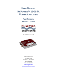
(1 each) Central Control Board Rev. 3 (CCB)
(1 each) Flame Control Board Rev. 3 (FCB)
(1 each) Wiring Instruction Insert Sheet
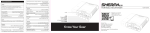
(1 each) Silicone Carbide Wiring Harness
(2 each) Wiring Butt Splices
(2 each) Male Amp Quick Connect Terminals
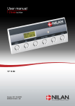
(1 each) Silicone Carbide Igniter
(1 each) Label “Converted to 400 Series”
(1 each) Instruction/Installation Manual (400 Series)
(1 each) Parts Manual (400 Series)
(1 each) User’s Manual (400 Series)
(1 each) Start-up Instructions (400 Series)
INSTRUCTIONS:
1. Turn off power to the unit using appropriate breaker in power distribution panel.
2. Remove Control Cover from unit.
3. The unit was originally wired for a silicone nitride igniter. The wiring harness for the igniter in the 300 Series is a
2-wire harness connected to a 3-pin plug that connects to J14 on the Central Control Board (CCB). The CCB is
the largest control board in the Control Shelve area and is mounted on the hinged, swing-down access door on
the left hand side of the unit.
4. Disconnect the existing Igniter Harness from J14 of the CCB. Cut the 2 wires of this harness as close to the 3-pin
Plug as possible and strip the wires back approximately 1/2". Discard the 3-pin Plug.
5. The newly supplied 2-wire Igniter Harness (approximately 6" long) has an Amp 2-pin Plug on one end and 2
stripped wire ends on the other end. Connect this harness to the two stripped wires from step 4 using supplied
butt splices and crimp the wires and harness together.
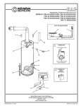
6. Remove the Igniter Access Panel from the lower Front Panel of the unit. Remove the Silicone Nitride Igniter from
the unit and discard. Cut off the 2 end Quick Connectors that had been plugged into the igniter from the harness
as close to the connectors as possible and discard. Strip the two wires to 1/2" and crimp the furnished Male Quick
Connects to the wires.
7. Install the new Silicone Carbide Igniter, connect connectors installed in step 6, close, and secure the Igniter
Access Panel.
8. Replace the existing CCB and FCB with the new boards from the kit, insuring that the new Boards' dip switches
are configured the same as those taken out.
9. Double check that all plugs have been reconnected and close Side Access Panel.
10.Reconnect Input power to the unit and turn power switch on. Verify operation.
11. Place Label ("Converted to 400 Series") furnished with Kit directly below the User Interface Module on the
Front Left Top Panel. The conversion will be accomplished as soon as the new Start-up Sheet is completed and
distributed.
PRINTED 0607
212695-000