1
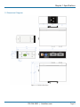
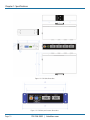
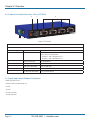
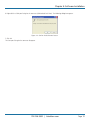
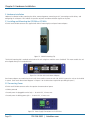
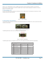
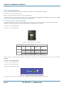
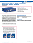
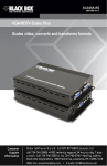
ICD120A ICD140A Industrial Isolated Converter User Manual Enables any host USB port to provide multiple RS-232, RS-422, or RS-485 two- or four-wire serial interfaces. 2- and 4-port versions are available. Customer Support Information Order toll-free in the U.S.: Call 877-877-BBOX (outside U.S. call 724-746-5500) FREE technical support 24 hours a day, 7 days a week: Call 724-746-5500 or fax 724-746-0746 Mailing address: Black Box Corporation, 1000 Park Drive, Lawrence, PA 15055-1018 Web site: www.blackbox.com • E-mail: [email protected] Trademarks Used in this Manual/Disclaimer Trademarks Used in this Manual Black Box and the Double Diamond logo are registered trademarks of BB Technologies, Inc. Any other trademarks mentioned in this manual are acknowledged to be the property of the trademark owners. Disclaimer: Black Box Network Services shall not be liable for damages of any kind, including, but not limited to, punitive, consequential or cost of cover damages, resulting from any errors in the product information or specifications set forth in this document and Black Box Network Services may revise this document at any time without notice. We‘re here to help! If you have any questions about your application or our products, contact Black Box Tech Support at 724-746-5500 or go to blackbox.com and click on “Talk to Black Box.” You’ll be live with one of our technical experts in less than 60 seconds. Page 2 724-746-5500 | blackbox.com FCC and IC RFI Statements/Safety/UL Class 1/Div 2 Explosion Hazard Warning Federal Communications Commission and Industry Canada Radio Frequency Interference Statements This equipment generates, uses, and can radiate radio-frequency energy, and if not installed and used properly, that is, in strict accordance with the manufacturer’s instructions, may cause interference to radio communication. It has been tested and found to comply with the limits for a Class A computing device in accordance with the specifications in Subpart B of Part 15 of FCC rules, which are designed to provide reasonable protection against such interference when the equipment is operated in a commercial environment. Operation of this equipment in a residential area is likely to cause interference, in which case the user at his own expense will be required to take whatever measures may be necessary to correct the interference. Changes or modifications not expressly approved by the party responsible for compliance could void the user’s authority to operate the equipment. This digital apparatus does not exceed the Class A limits for radio noise emission from digital apparatus set out in the Radio Interference Regulation of Industry Canada. Le présent appareil numérique n’émet pas de bruits radioélectriques dépassant les limites applicables aux appareils numériques de la classe A prescrites dans le Règlement sur le brouillage radioélectrique publié par Industrie Canada. Safety All safety related regulations, local codes and instructions that appear in the literature or on equipment must be observed to ensure personal safety and to prevent damage to either the instrument or equipment connected to it. If equipment is used in a manner not specified by the manufacturer, the protection provided by the equipment may be impaired. UL Class 1, Div. 2 Explosion Hazard Warning Suitable for use in Class 1, Division 2, Groups A, B, C, and D Hazardous Locations, or Nonhazardous locations only. WARNING — EXPLOSION HAZARD — DO NOT DISCONNECT EQUIPMENT WHILE THE CIRCUIT IS LIVE UNLESS THE AREA IS KNOWN TO BE FREE OF IGNITABLE CONCENTRATIONS. Install in accordance with control drawing number 9340R0 Ind. Cont. Eq. For HAZ LOC 3HTV E245548 Class 1, Div. 2, Groups A, B, C, & D Temp. Code: T4 724-746-5500 | blackbox.com Page 3 NOM Statement Instrucciones de Seguridad (Normas Oficiales Mexicanas Electrical Safety Statement) 1. T odas las instrucciones de seguridad y operación deberán ser leídas antes de que el aparato eléctrico sea operado. 2. Las instrucciones de seguridad y operación deberán ser guardadas para referencia futura. 3. Todas las advertencias en el aparato eléctrico y en sus instrucciones de operación deben ser respetadas. 4. T odas las instrucciones de operación y uso deben ser seguidas. 5. E l aparato eléctrico no deberá ser usado cerca del agua—por ejemplo, cerca de la tina de baño, lavabo, sótano mojado o cerca de una alberca, etc. 6. E l aparato eléctrico debe ser usado únicamente con carritos o pedestales que sean recomendados por el fabricante. 7. El aparato eléctrico debe ser montado a la pared o al techo sólo como sea recomendado por el fabricante. 8. S ervicio—El usuario no debe intentar dar servicio al equipo eléctrico más allá a lo descrito en las instrucciones de operación. Todo otro servicio deberá ser referido a personal de servicio calificado. 9. El aparato eléctrico debe ser situado de tal manera que su posición no interfiera su uso. La colocación del aparato eléctrico sobre una cama, sofá, alfombra o superficie similar puede bloquea la ventilación, no se debe colocar en libreros o gabinetes que impidan el flujo de aire por los orificios de ventilación. 10. E l equipo eléctrico deber ser situado fuera del alcance de fuentes de calor como radiadores, registros de calor, estufas u otros aparatos (incluyendo amplificadores) que producen calor. 11. E l aparato eléctrico deberá ser connectado a una fuente de poder sólo del tipo descrito en el instructivo de operación, o como se indique en el aparato. 12. P recaución debe ser tomada de tal manera que la tierra fisica y la polarización del equipo no sea eliminada. 13. L os cables de la fuente de poder deben ser guiados de tal manera que no sean pisados ni pellizcados por objetos colocados sobre o contra ellos, poniendo particular atención a los contactos y receptáculos donde salen del aparato. 14. El equipo eléctrico debe ser limpiado únicamente de acuerdo a las recomendaciones del fabricante. 15. E n caso de existir, una antena externa deberá ser localizada lejos de las lineas de energia. 16. El cable de corriente deberá ser desconectado del cuando el equipo no sea usado por un largo periodo de tiempo. 17. Cuidado debe ser tomado de tal manera que objectos liquidos no sean derramados sobre la cubierta u orificios de ventilación. 18. S ervicio por personal calificado deberá ser provisto cuando: A: El cable de poder o el contacto ha sido dañado; u B: Objectos han caído o líquido ha sido derramado dentro del aparato; o C: El aparato ha sido expuesto a la lluvia; o D: El aparato parece no operar normalmente o muestra un cambio en su desempeño; o E: El aparato ha sido tirado o su cubierta ha sido dañada. Page 4 724-746-5500 | blackbox.com Table of Contents Table of Contents 1. Specifications..........................................................................................................................................................................6 1.1 General Specifications....................................................................................................................................................6 1.2Approvals.......................................................................................................................................................................7 1.3 Basic Default Settings.....................................................................................................................................................7 1.4 Advanced Default Settings.............................................................................................................................................8 1.5 Dimensional Diagrams....................................................................................................................................................9 2. Overview.............................................................................................................................................................................. 12 2.1Description................................................................................................................................................................... 12 2.2Features........................................................................................................................................................................ 12 2.3 What’s Included........................................................................................................................................................... 12 2.4 Hardware Description................................................................................................................................................... 13 2.4.1 Industrial Isolated Converter, 2-Port (ICD120A)................................................................................................. 13 2.4.2 Industrial Isolated Converter, 4-Port (ICD140A)................................................................................................. 14 2.5 Typical Application/Modes of Operation...................................................................................................................... 14 3. Quick Start Guide................................................................................................................................................................. 15 4. Software Installation............................................................................................................................................................. 17 4.1 Installing the Driver....................................................................................................................................................... 17 4.2 Un-installing the Driver................................................................................................................................................. 18 5. Hardware Installation............................................................................................................................................................20 5.1 Installing and Mounting the ICD120A or ICD140A.......................................................................................................20 5.2 Connecting Power........................................................................................................................................................20 5.3 Connecting to a PC...................................................................................................................................................... 21 5.4 Connecting to the Serial Ports...................................................................................................................................... 21 5.5 Termination and Biasing...............................................................................................................................................22 5.6 Setting COM Port Operating Modes............................................................................................................................22 5.7 LED Indicators...............................................................................................................................................................23 6. Advanced User Settings........................................................................................................................................................24 6.1 Setting Serial Port Properties........................................................................................................................................24 6.2 Advanced Settings in Device Manager.........................................................................................................................25 6.3 Modbus Basics..............................................................................................................................................................26 Appendix A. Loopback Test and Serial Port Wiring....................................................................................................................27 A.1 Loopback Test..............................................................................................................................................................27 A.2 Serial Port Wiring.........................................................................................................................................................29 Appendix B. Troubleshooting.....................................................................................................................................................32 724-746-5500 | blackbox.com Page 5 Chapter 1: Specifications 1. Specifications 1.1 General Specifications Baud Rate (kbps) 300, 600, 1200, 1800, 2400, 4800, 7200, 9600, 14400, 19200, 38400, 57600, 115200, 230400, 460800, 921600 Data Bits 5, 6, 7, 8 Parity None, Odd, Even Stop Bit(s) 0, 1, 2 Driver WHQL Isolation 2 kV port to port Enclosure Mounting DIN adapter, panel mounting with mounting kit Operating Systems Supported Server 2008 R2, Windows 7, Windows 7 x64, Windows Server 2008, Windows Server 2008 x64, Windows Vista, Windows Vista x64, Windows Server 2003, Windows Server 2003 x64, WIndows XP, Windows XP x64, Windows 2000 Protocols USB 1.1 and 2.0 RS-232 Lines Supported TD, RD, RTS, CTS, DTR, DSR, DCD, GND RS-422/485 Lines (4-wire) TDA(-), TDB(+), RDA(-), RDB(+), GND RS-485 Lines (2-wire) DATA A(-), DATA B(+), GND RS-422/485 HS Loopback Loopback RTS to CTS, DTR to DSR/DCD Serial Modes RS-232 (DTE), RS-485 (2-wire), RS-485 (4-wire) Speed User Controls Connectors 1.5 Mbps, 12 Mbps, 480 Mbps (1) Quad DIP switch for user hardware selection per port ICD120A: Upstream: (1) USB Type B high-retention (15 Newton/3.4 lb. withdrawal force); Serial Port: (2) DB9 connectors; ICD140A: Upstream: (1) USB Type B high-retention (15 Newton/3.4 lb. withdrawal force); Serial Port: (4) DB9 connectors; Power Connector (ICD120A and ICD140A): (1) 3-position removable terminal block, (1) threaded barrel jack with center positive (+) Indicators ICD120A: (4) Communication LEDs: P1 TX, P1 RX, P2 TX, P2 RX blink green when data is present, (1) Power LED (continuously ON if powered via an external power supply or terminal block); ICD140A: (8) Communication LEDs: P1 TX, P1 RX, P2 TX, P2 RX, P3 TX, P4 RX, P4 TX, P4 RX blink green when data is present, (1) Power LED (continuously ON if powered via an external power supply or terminal block) Power 10-VDC to 48-VDC power supply (not included); (1) 3-position removable terminal block, (1) threaded barrel jack with center positive (+) Dimensions ICD120A: 1.4"H x 5.4"W x 3.5"D (3.5 x 13.8 x 8.8 cm); ICD140A: 1.4"H x 8"W x 4.7"D (3.5 x 20.3 x 12 cm) Weight ICD120A: 0.88 lb. (0.40 kg); ICD140A: 1.5 lb. (0.68 kg) Page 6 724-746-5500 | blackbox.com Chapter 1: Specifications 1.2 Approvals UL Class 1, Div 2 Emissons FCC Class B, CISPR Class B (EN55022) CE EN61000-6-2:2005 — Heavy industrial; EN61000-4-2:2005 — (ESD) ±8 kV contact, ±15 kV air; EN61000-4-3:2006 — (RI) 10 Vm. 80 to 1000 <Jz; 3 V/M. 1.3 to 2.7 GHz; EN61000-4-4:2004 — (EFT Burst) ±2 kV DC ports; ±1kV signal ports; EN61000-4-5:2005 — (Surge) ±1 kV signal ports; EN61000-4-6:2006 — (CI) 10 VRMS, 0.15 to 80 MHz; EN61000-4-8:2001 — (Magnetic) 10 A/m, 50 Hz and 60 Hz; Shock IEC60068-2-27 — 50G peak, 11 ms, 3 axis Vibration IEC60068-2-6 — 10 to 500 Hz, 4G, 3 axis Freefall (drop) IEC60068-2-32 — 10 total drops from sides, corner and edges; 1 M UL Class 1, Div. 2 Suitable for use in Class 1, Division 2, Groups A, B, C, and D Hazardous Locations, or Nonhazardous locations only. WARNING — EXPLOSION HAZARD — DO NOT DISCONNECT EQUIPMENT WHILE THE CIRCUIT IS LIVE UNLESS THE AREA IS KNOWN TO BE FREE OF IGNITABLE CONCENTRATIONS. Install in accordance with control drawing number 9340R0 Ind. Cont. Eq. For HAZ LOC 3HTV E245548 Class 1, Div. 2, Groups A, B, C, & D Temp. Code: T4 1.3 Basic Default Settings Serial Interface RS-232 (both DIP switches OFF) Bits per second 9600 Data bits 8 Parity None Stop Bits 1 Flow Control None COM Port First available over COM port 4 724-746-5500 | blackbox.com Page 7 Chapter 1: Specifications 1.4 Advanced Default Settings USB Transfer Size —Receive 4096 bytes (max.) USB Transfer Size — Transmit 4096 bytes (max.) Latency Timer 16 Minimum Read Timeout 0 Minimum Write Timeout 0 Serial Enumerator On Serial Printer Off Cancel If Power Off Off Event On Surprise Removal Off Set RTS on Close Off Disable Modem Ctrl at Startup Off Page 8 724-746-5500 | blackbox.com Chapter 1: Specifications 1.5 Dimensional Diagrams Figure 1-1. ICD120A dimensions. 724-746-5500 | blackbox.com Page 9 Chapter 1: Specifications Figure 1-2. ICD140A dimensions. Figure 1-3. ICD120A panel mount dimensions. Page 10 724-746-5500 | blackbox.com Chapter 1: Specifications Figure 1-4. ICD140A panel mount dimensions. 724-746-5500 | blackbox.com Page 11 Chapter 2: Overview 2. Overview 2.1 Description The Industrial Isolated Converters enable any host USB port to provide multiple RS-232, RS-422 or RS-485 two or four-wire serial interfaces. The ICD120A provides two ports; the ICD140A provides four ports. These converters support USB 2.0 high speed data rates of 480 Mbps. The upstream and downstream sections are isolated to 2000 volts. Industrial features include a rugged metal case, versatile mounting options, high ESD protection, wide temperature ranges, and high-retention USB connectors. 2.2 Features • Easy to install • 2 kV port-to-port isolation • High retention USB connector • Rugged metal case • DIN rail or panel mount options included • 8 kV contact, 15 kV air ESD surge protection • Wide temperature range (-40 to +176° F [-40 to +80° C]) • USB 2.0 and 1.1 compatible • LEDs indicate power and port status • Includes 2 meter USB cable • USB powered (USR602 only) or externally powered • Redundant power inputs (10 to 48 VDC) via terminal block or locking barrel jack • Drivers for Windows 2000 and up (including 64-bit variants) • RS-232, RS-422, RS-485 two-wire and RS-485 four-wire interfaces • Modbus support • 2 or 4 port models 2.3 What’s Included Your package should include the following items. If anything is missing or damaged, contact Black Box Technical Support at 724-746-5500 or [email protected]. • (1) Industrial Isolated Converter, 2-Port (ICD120A) or Industrial Isolated Converter, 4-Port (ICD140A) • (1) 6.4-ft. (2-m) USB cable • (2) brackets and (4) screws for panel mounting • DIN rail mount adapter • Quick Start Guide This user manual/installation guide can be downloaded from the Black Box Web site. To download from the Web site: 1. Go to www.blackbox.com Page 12 724-746-5500 | blackbox.com Chapter 2: Overview 2. Enter the part number in the search box: 3. C lick on the “Resources” tab on the product page, and select the document you wish to download. If you have any trouble accessing the Black Box site to download the manual, you can contact our Technical Support at 724-746-5500 or [email protected]. 2.4 Hardware Description 2.4.1 Industrial Isolated Converter, 2-Port (ICD120A) Figure 2-1 shows the ICD120A. Table 2-1 describes its components. 3 1 4 5 6 2 Figure 2-1. ICD120A. Table 2-1. ICD120A components. Number in Figure 2-1 Component Description 1 3-pin terminal jack Used for power 2 Barrel jack Used for power 3 USB Type B connector Links to USB host 4 DIP switches Used to configure serial ports for RS-232, RS-422, RS-485 (4-wire), or RS-485 (2-wire) operation: Switches 1 and 2 configure Port 1; Switches 3 and 4 configure Port 2 5 LEDs (4) LEDs: P1 TX, P1 RX, P2 TX, P2 RX 6 (2) DB9 male connectors Links to serial devices 724-746-5500 | blackbox.com Page 13 Chapter 2: Overview 2.4.2 Industrial Isolated Converter, 4-Port (ICD140A) 4 1 2 5 6 3 Figure 2-2. ICD140A. Table 2-2. ICD140A components. Number in Figure 2-2 Component Description 1 DIP switches Used to configure serial ports for RS-232, RS-422, RS-485 (4-wire), or RS-485 (2-wire) operation: Switches 1 and 2 configure Port 1; Switches 3 and 4 configure Port 2 2 3-pin terminal jack Used for power 3 Barrel jack Used for power 4 USB Type B connector Links to USB host 5 LEDs (4) LEDs: P1 TX, P1 RX, P2 TX, P2 RX 6 (2) DB9 male connectors Links to serial devices 2.5 Typical Applications/Modes of Operation • Add serial ports to PCs • Convert USB serial connection to: - RS-232 - RS-422 - RS-485 two-wire - RS-485 four-wire Page 14 724-746-5500 | blackbox.com Chapter 3: Quick Start Guide 3. Quick Start Guide What’s Included Before you begin, make sure you have the following items: • (1) ICD120A or ICD140A • (1) 6.4-ft. (2-m) USB cable • (2) brackets and (4) screws for panel mounting • DIN rail mount adapter Installation Steps STEP 1: Install the drivers. NOTE: To prevent installation errors, do not plug in the hardware until you have already installed the drivers. Use the included CD to install the converter’s drivers in the attached PC. STEP 2: Set DIP Switches. Refer to the tables below and the following illustrations. Table 3-1. DIP switches on the ICD120A. DIP Switch SW # RS-232 RS-422 RS-485 4-Wire RS-485 2-Wire Port 1 1 OFF ON OFF ON 2 OFF ON ON OFF 3 OFF ON OFF ON 4 OFF ON ON OFF Port 2 DIP switches LEDs USB port Port 1 and Port 2 DB9 M connectors 3-pin terminal block and barrel jack for power Table 3-2. DIP switches on the ICD140A. DIP Switch SW # RS-232 RS-422 RS-485 4-Wire RS-485 2-Wire Port 1 1 OFF ON OFF ON 2 OFF ON ON OFF 3 OFF ON OFF ON 4 OFF ON ON OFF 5 OFF ON OFF ON 6 OFF ON ON OFF 7 OFF ON OFF ON 8 OFF ON ON OFF Port 2 Port 3 Port 4 LEDs USB port Ports 1–4 DB9 M connectors DIP switches 3-pin terminal block and barrel jack for power STEP 3: Power the Converter. The ICD120A can run on 5 V USB power if the host port is providing 500 mA. It can also be powered via the terminal block or barrel jack port. 724-746-5500 | blackbox.com Page 15 Chapter 3: Quick Start Guide STEP 4: Connect the Converter. When you connect the converter to the host computer’s USB port, the Found New Hardware wizard will open. It will discover and install the USB device. Then it will discover and install each serial port. Allow Windows to install the converter “Automatically.” There is no need to connect to the Internet or Windows Update. If a popup window says the software has not passed Windows logo testing, that’s OK. Just click on “Continue Anyway.” When the wizard is complete, the serial ports on the converter will appear in Windows Device Manager as new COM ports. STEP 5: Configure the Serial Ports. Open Control Panel. Click “System” to open the Device Manager. Under “Ports,” double-click the port to be configured. On the “Serial Port Properties” window, set the required communications parameters for the system with which you are communicating. If necessary, click Advanced and set up the Advanced Properties. (Refer to the user manual for more information.) To download the user manual from the Black Box Web site: 1. Go to www.blackbox.com 2. Enter the part number (ICD120A) in the search box: 3. C lick on the “Resources” tab on the product page, and select the document you wish to download. STEP 6: Loopback Test. Set the converter to RS-232 mode using the DIP switches. Loopback pins 2 and 3. Using HyperTerminal or a similar program, connect to the COM port. Set the desired baud rate. Ensure that HyperTerminal local echo is OFF. Transmit data. If the same character string is returned, the test is good. STEP 7: LEDs. Type Indication when ON PWR Computer is receiving adequate voltage and current from USB or power source. TX Serial interface is transmitting data. RX Serial interface is receiving data. Page 16 724-746-5500 | blackbox.com Chapter 4: Software Installation 4. Software Installation CAUTION: D o not connect the converter to your PC until the driver is installed. Download the driver from www.blackbox.com. It is installed using an executable program. This program must be run on your PC before connecting the converter to your USB port. 4.1 Installing the Driver Download the driver from the Black Box web site (www.blackbox.com). The driver installation software should automatically start. If not, double-click on the “setup.exe” file. The following dialog box will appear. Figure 4-1. Run setup.exe dialog. 1. Click Next. The license agreement dialog box will appear. Figure 4-2. End User License Agreement. 2. Click Next. The program will install the drivers on your computer and the installation complete screen will appear. 724-746-5500 | blackbox.com Page 17 Chapter 4: Software Installation Figure 4-3. Installation Complete Screen. 3. W hen the installation is complete, you can plug in the USB to Serial Converter. When you do this, the COM ports will be assigned. It may take up to 30 seconds to assign the COM ports the first time you plug in the converter. 4. The driver software is now installed. 5. To verify that the communication port has been configured: a. Open the Control Panel. b. Click System to open the System Properties dialog box. c. Select the Hardware tab. d. Click Device Manager to open the Device Manager dialog box. e. Expand Ports (COM & LPT). USB Isolated Serial Port should be listed as one of the COM ports. 4.2 Un-Installing the Driver To un-install the driver for the ICD120A or ICD140A converter: 1. Open the Control Panel. 2. Click System to open the System Properties dialog box. 3. Select the Hardware tab. 4. Click Device Manager to open the Device Manager dialog box. 5. Expand Ports (COM & LPT). USB Isolated Serial Port should be listed as one of the COM ports. Page 18 724-746-5500 | blackbox.com Chapter 4: Software Installation 6. Right-click the COM port listing for the converter (USB Isolated Serial Port). The following dialog box appears. Figure 4-4. Confirm Device Removal screen. 7. Click OK. The Com port listing for the converter disappears. 724-746-5500 | blackbox.com Page 19 Chapter 5: Hardware Installation 5. Hardware Installation Hardware installation includes mounting the device, connecting power, connecting to a PC, connecting to serial devices, and configuring the serial ports. LEDs indicate the presence of power and communications signals on the ports. 5.1 Installing and Mounting the ICD120A or ICD140A ICD120A and ICD140A converters are supplied with DIN rail mounting clips and panel mount adapters. Figure 5-1. DIN Rail Mounting Clip. The DIN rail mounting clip is attached to the back of the unit using three machine screws (included). This mount enables the unit to be clipped directly to a standard DIN rail. Figure 5-2. ICD120A with Panel Mount Adapters. Panel mount adapters are attached to the unit with three machine screws on each side. With this mount the unit can be installed in a panel. (Refer to the dimensional diagrams in Chapter 1 for the dimensions required for pre-drilling the panel.) 5.2 Connecting Power ICD120A and ICD140A converters offer three options for connection of power: • USB bus powered • External power via pluggable terminal strip — 10 to 48 VDC, 16 watts max. • External power via locking power jack — 10 to 48 VDC, 16 watts max. Figure 5-3. Power Supply Connections on the ICD120A. Page 20 724-746-5500 | blackbox.com Chapter 5: Hardware Installation When the unit is USB powered, the current available to the converter may be limited by the USB host. If the converter is connected to an external USB hub, the maximum available current may be insufficient to operate the converter. In that case, connect an external power supply. 5.3 Connecting to a PC ICD120A and ICD140A converters connect to a host device (PC) via a USB interface. The connector on the converter is a highretention force Type B female connector. Figure 5-4. USB Connector. 5.4 Connecting to the Serial Ports The ICD120A has two serial ports; the ICD140A has four. DB9 M connectors are used for RS-232, RS-422, and RS-485 two-wire and four-wire connections. Figure 5-5. DB9 M Serial Port Connectors. The following illustration shows the pin numbering of the DB9 M connector. Figure 5-6. DB9 F Pin Numbering. The following table shows the wiring pin-outs for RS-232, RS-422 and RS-485 two-wire and four-wire connections. Table 5-1. DB9 F wiring pinouts. Pins RS-232 (DTE) RS-422/RS-485 (4-wire) RS-485 (2-wire) 1 Data Carrier Detect (DCD) RDA(-) — 2 Receive Data (RD) RDB(+) — 3 Transmit Data (TD) TDB(+) DATA B(+) 4 Data Terminal Ready (DTR) TDA(-) DATA A(-) 5 Signal Ground (GND) GND GND 6 Data Set Ready (DSR) — — 7 Request to Send (RTS) — — 8 Clear to Send (CTS) — — 9 Not Used — — 724-746-5500 | blackbox.com Page 21 Chapter 5: Hardware Installation 5.5 Termination and Biasing ICD120A and ICD140A converters include internal biasing resistors on the RS-422/RS-485 interfaces. The values for internal biasing resistors are: Biasing: 1k ohms (default IN PLACE when in RS-422/485 modes) The biasing resistors are connected to the receive lines, pulling the RDA(-) line to ground and the RDB(+) line to a positive voltage. The bias resistor is automatically IN when you select RS-422/485 mode. 5.6 Setting COM Port Operating Modes The operating modes of the converter are configured by the positions of DIP switches accessible on the ICD120A or ICD140A enclosure. The DIP switches on the ICD120A are located on the front panel of the converter. • Switches 1 and 2 configure Port 1 • Switches 3 and 4 configure Port 2 Figure 5-7. DIP Switches on the ICD120A. Table 5-2. DIP switch settings on the ICD120A. DIP Switch SW # RS-232 RS-422 RS-485 4-Wire RS-485 2-Wire Port 1 1 OFF (down) ON (up) OFF (down) ON (up) 2 OFF (down) ON (up) ON (up) OFF (down) 3 OFF (down) ON (up) OFF (down) ON (up) 4 OFF (down) ON (up) ON (up) OFF (down) Port 2 The DIP switches on the ICD140A are located on the top of the enclosure near the power connectors (when the unit is positioned vertically). • Switches 1 and 2 configure Port 1 • Switches 3 and 4 configure Port 2 • Switches 5 and 6 configure Port 3 • Switches 7 and 8 configure Port 4 Figure 5-8. ICD140A DIP Switch and Power Connectors. Operating modes are RS-232, RS-485 two-wire half-duplex, RS-485 four-wire full-duplex, and RS-422. Page 22 724-746-5500 | blackbox.com Chapter 5: Hardware Installation Table 5-3. DIP switch settings on the ICD140A. DIP Switch SW # RS-232 RS-422 RS-485 4-Wire RS-485 2-Wire Port 1 1 OFF (down) ON (up) OFF (down) ON (up) 2 OFF (down) ON (up) ON (up) OFF (down) 3 OFF (down) ON (up) OFF (down) ON (up) 4 OFF (down) ON (up) ON (up) OFF (down) 5 OFF (down) ON (up) OFF (down) ON (up) 6 OFF (down) ON (up) ON (up) OFF (down) 7 OFF (down) ON (up) OFF (down) ON (up) 8 OFF (down) ON (up) ON (up) OFF (down) Port 2 Port 3 Port 4 5.7 LED Indicators ICD120A converters include five LED indicators; ICD140A converters include nine LED indicators. In both models, one indicates the presence of power; the others indicate transmit and receive data present on each port. Figure 5-9. ICD120A LED Indicators. Figure 5-10. ICD140A LED Indicators. Table 5-4. LED indicators on the ICD120A and ICD140A. LED Function Color Indicates Power Green Presence of power Port 1 RX Blinking green Data is being received on Port 1 Port 1 TX Blinking yellow Data is being transmitted on Port 1 Port 2 RX Blinking green Data is being received on Port 2 Port 2 TX Blinking yellow Data is being transmitted on Port 2 Port 3 RX Blinking green Data is being received on Port 3 Port 3 TX Blinking yellow Data is being transmitted on Port 3 Port 4 RX Blinking green Data is being received on Port 4 Port 4 TX Blinking yellow Data is being transmitted on Port 4 724-746-5500 | blackbox.com Page 23 Chapter 6: Advanced User Settings 6. Advanced User Settings Serial port parameters and other advanced settings are configured on the USB Isolated Serial Port Properties and Advanced Settings windows, which are accessible via the Device Manager. The Device Manager can be accessed through the Windows® Control Panel. Figure 6-1. Device Manager. 6.1 Setting Serial Port Properties 1. In Device Manager, expand Ports and double-click USB Isolated Serial Port to open the USB Isolated Serial Port Properties dialog box. Figure 6-2. Port Properties. Page 24 724-746-5500 | blackbox.com Chapter 6: Advanced User Settings 2. In the dropdown lists provided, select the following serial port properties required for your communications application: • Bits per second • Data bits • Parity • Stop bits • Flow control NOTE: The default values for this dialog are 9600 bps, 8 data bits, No parity, 1 stop bit, No flow control. 6.2 Advanced Settings in Device Manager To configure advanced settings, on the USB Isolated Serial Port Properties dialog, click Advanced... The Advanced Settings dialog appears. Figure 6-3. Advanced Settings. Configure the advanced settings as required (refer to the following sections for details) and click OK to store the settings. COM Port Number When installing the drivers, the first available COM port number is assigned to the first COM port on the ICD120A or ICD140A device. If necessary, the default communications port number can be changed by selecting a new number in the COM Port Number dropdown list. USB Transfer Sizes Receive and transmit message sizes between 64 bytes and 4096 bytes can be selected. The default value is 4096. Select lower settings to correct performance problems at low baud rates. Select higher settings for faster performance. BM Options The BM Options dropdown list provides a setting for the Latency Timer. The latency timer is a form of time-out mechanism that counts from the last time data was sent from the ICD120A or ICD140A back to the PC. If the latency timer expires, the ICD120A or ICD140A will send any data it has available to the PC. It then resets and begins counting again. Timer settings from 1 to 255 msecs are available. The default value is 16 msec. Select lower settings to correct response problems. 724-746-5500 | blackbox.com Page 25 Chapter 6: Advanced User Settings Timeouts The USB timeout is the maximum time in milliseconds that a USB request can remain outstanding. Minimum read and write timeout values between 0 and 10000 msec can be selected. The default values are 0 for both read and write timeouts. Miscellaneous Options The following settings can be selected or deselected by clicking the appropriate checkbox: • S erial Enumerator — The function of the serial enumerator is to detect a Plug-and-Play enabled device (such as a serial mouse or serial modem) that is attached to the USB serial port. • Serial Printer — If enabled, serial printer will disable timeouts to allow for long delays associated with paper loading. •C ancel If Power Off — The Cancel If Power Off option can be used to assist with problems encountered when going into a hibernate or suspend condition. This will cancel any requests received by the driver when going into hibernate or suspend. • Event On Surprise Removal — The Event On Surprise Removal option is generally left unselected. • Set RTS On Close — Selecting the Set RTS On Close option will set the RTS signal on closing the port. •D isable Modem Ctrl At Startup — This option is used to control the modem control signals DTR and RTS at startup. Devices that monitor these signals can enter the wrong state after an unplug-replug cycle on USB. 6.3 Modbus Basics Modbus is an industrial data communications protocol that emerged in the mid-1970s and continues to be widely used in current industrial systems. Originally designed to link terminals with Modicon PLCs, it is simple, easy to learn and implement, and free to use. It quickly became a defacto standard in the industry and has been widely implemented with successful results. Modbus is a message-based master/slave protocol (also sometimes referred to as master/client) typically implemented across serial communications links such as RS-232, RS-422, and RS-485. It supports asynchronous point-to-point and multidrop communications. The original Modbus specification included two possible transmission modes: ASCII and RTU. Modbus RTU mode is the most common implementation, using binary coding and CRC error-checking. Modbus ASCII messages (though somewhat more readable because they use ASCII characters) is less efficient and uses less effective LRC error checking. ASCII mode uses ASCII characters to begin and end messages whereas RTU uses time gaps (3.5 character times) of silence for framing. The two modes are incompatible so a device configured for ASCII mode cannot communicate with one using RTU. Although some newer equipment using Modbus incorporates USB interfaces, most legacy equipment implements RS-232, RS-422, and RS-485. Most new PCs have eliminated RS-232 ports as standard features and RS-422/485 was never a standard feature. As a result USB to serial converters such as the ICD120A and ICD140A are often necessary to communicate between PCs and legacy systems that implement Modbus protocol. Page 26 724-746-5500 | blackbox.com Appendix A: Loopback Test and Serial Port Wiring Appendix A: Loopback Test and Serial Port Wiring A.1 Loopback Test To verify the operation of the USB to serial converter, perform a loopback test using the following procedure: 1. C onnect the converter to the PC with a USB cable and install the driver using the procedure provided in the Software Installation section of this manual. 2. On the PC, open HyperTerminal (found in the Program files under Accessories/Communications). Figure A-1. Hyperterminal Connection Name. 3. Enter a connection name and click OK. Figure A-2. Selecting the COM Port. 4. On the Connection using: dropdown list, select the port on the converter to be tested. 5. Click OK. 724-746-5500 | blackbox.com Page 27 Appendix A: Loopback Test and Serial Port Wiring Figure A-3. Setting the Port Settings. 6. On the Properties/Port Settings dialog, ensure Flow control is set to None. 7. Click OK. 8. Set the serial port to RS-232 mode by switching both associated DIP switches to Off. 9. Plug a loopback plug into the DB9 M connector associated with the serial port to be tested. Figure A-4. Loopback plug. 10. Type some characters on the PC’s keyboard. The characters should appear on the HyperTerminal window. Figure A-4. Successful Hyperterminal Port Test. 11. Remove the loopback plug and type more characters. No additional characters should appear on the HyperTerminal window. Page 28 724-746-5500 | blackbox.com Appendix A: Loopback Test and Serial Port Wiring A.2 Serial Port Wiring RS-232 Connections Figure A-6. ICD120A RS-232 Connections. 724-746-5500 | blackbox.com Page 29 Appendix A: Loopback Test and Serial Port Wiring RS-485 Two-Wire Connections Figure A-7. ICD120A RS-485 Two-Wire Connections. Page 30 724-746-5500 | blackbox.com Appendix A: Loopback Test and Serial Port Wiring RS-422 and RS-485 Four-Wire Connections Figure A-8. ICD120A RS-422/485 Four-Wire Connections. 724-746-5500 | blackbox.com Page 31 Appendix B: Troubleshooting Appendix B. Troubleshooting One USB port is required for each installed device. The USB port can be native to the PC or it can be a USB port on a USB hub that is connected to a PC. The device works with USB 1.1 or 2.0 ports. But it has a maximum USB data rate of 12 Mbps. To verify the installation, you may open the Windows Device Manager. Scroll down to Ports. Expand the flyout window. You should see the new ports. If there are no exclamation points or other trouble indicators the ports are installed correctly and ready for use. Sleep & Hibernate: Windows 7 disables USB transmit while in Sleep & Hibernate. Terminal Block • One conductor per terminal. • Use copper wire only. • Wire size 16 to 28 AWG. • Tightening torque 5 KG -CM. Page 32 724-746-5500 | blackbox.com NOTES 724-746-5500 | blackbox.com Page 33 NOTES Page 34 724-746-5500 | blackbox.com NOTES 724-746-5500 | blackbox.com Page 35 Black Box Tech Support: FREE! Live. 24/7. Tech support the way it should be. Great tech support is just 60 seconds away at 724-746-5500 or blackbox.com. About Black Box Black Box provides an extensive range of networking and infrastructure products. You’ll find everything from cabinets and racks and power and surge protection products to media converters and Ethernet switches all supported by free, live 24/7 Tech support available in 60 seconds or less. © Copyright 2014. Black Box Corporation. All rights reserved. Black Box® and the Double Diamond logo are registered trademarks of BB Technologies, Inc. Any third-party trademarks appearing in this manual are acknowledged to be the property of their respective owners. ICD120A_ICD140A user manual version 1 724-746-5500 | blackbox.com