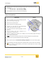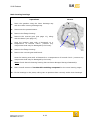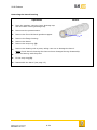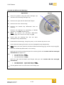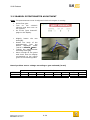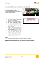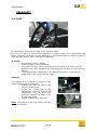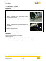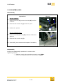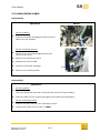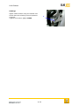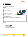
1
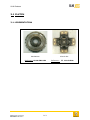
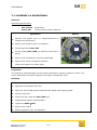
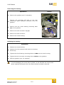
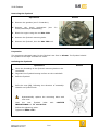
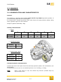
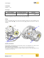
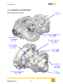
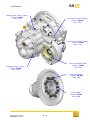
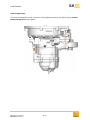
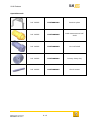
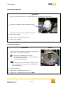
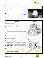
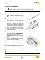
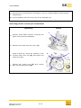
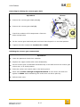
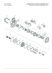
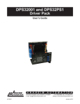
USER MANUAL D. Transmission 2010 Release 3 TRANSMISSION CONTENTS 3 TRANSMISSION 3.1 3.1.1 3.1.2 3.2 3.2.1 3.2.2 3.2.3 3.2.4 3.3 3.3.1 3.3.2 3.3.3 3.3.4 3.4 3.4.1 3.5 2 CLUTCH PRESENTATION ASSEMBLY & DISASSEMBLY GEARBOX PRESENTATION AND CHARACTERISTICS ASSEMBLY & DISASSEMBLY BARREL POTENTIOMETER ADJUSTMENT ENGINE CUT-OFF CONTACTOR ADJUSTMENT GEARSHIFT USE GEARSHIFT LEVER CONTROL ROD UNLOCKING CABLE TRANSMISSION ASSEMBLY & DISASSEMBLY TIGHTENING TORQUES D-2 3 3 4 7 7 9 26 27 28 28 29 30 31 33 33 36 2010 Release 3.1 CLUTCH 3.1.1 PRESENTATION Mechanism Clutch disc Reference: 82 00 581 884 D-3 Reference: 77 11 162 520 2010 Release 3.1.2 ASSEMBLY & DISASSEMBLY Removal Essential special tooling Mot. 582-01 Emb 1780 Stop sector Clutch friction locator collection Operations 1- Photos Remove the engine (see 2-1 Engine/Removing & refitting the powertrain). 2 - Remove the gearbox (see 3-2 Gearbox). 3 - Fit the stop sector Mot. 582. 4- 1 Fit the locator Emb 1780 (to hold the clutch disc in place). 5 - Remove the mechanism’s mounting bolts (1). 6 - Remove the clutch mechanism and disc. Check and replace any faulty parts. Inspection The maximum tolerated taper for the clutch mechanism's pressure plates is 0.3mm. The clutch mechanism should be replaced if the taper exceeds this value. Refitting Operations 1 - Degrease the flywheel rear face. 2 - Clean the input shaft grooves and lubricate lightly with copper grease. 3 - Fit the clutch disc. 4 - Center the disc using the Emb 1780 tool. 5 - Progressively tighten opposing bolts. 6 - Tighten to 20Nm 10%. 7 - Remove the locator. 8 - Refit the gearbox (see 3-2 Gearbox). D-4 2010 Release Removing the bearing Operations Photos 1 - Remove the gearbox (see 3-2 Gearbox). Remove the mounting bolt (1) of the CSC 2 - (Concentric Slave Cylinder) connector from the gearbox. 3- Remove the two clutch bearing mounting bolts (2) on the gearbox. 1 3 4 - Remove the CSC connector clip (3). 5 - Remove the CSC connector. 2 6 - Remove the clutch bearing. Refitting the bearing Operations 1 - Position the clutch bearing. 2 - Position the CSC connector and insert into bearing. 3 - Fit the clip. 4 - Tighten the clutch bearing mounting bolts to 21Nm on the clutch housing. 5 - Tighten the CSC connector mounting bolt to 21Nm on the gearbox. 6 - Refit the gearbox (see 3-2 Gearbox). To avoid damaging the clutch slave cylinder, do not lubricate the clutch shaft. Never operate the system when the slave cylinder has been removed. D-5 2010 Release Removing the flywheel Operations Photos 1 - Remove the gearbox (see 3-2 Gearbox). 2- Remove the clutch mechanism Clutch/Assembly & disassembly). (see 3-1 3 - Block the engine using the tool Mot. 582. 4 - Remove the flywheel mounting bolts. 5 - Remove the flywheel, then the Mot. 582 tool. Inspection The maximum tolerated taper for the flywheel rear face is 0.3mm. The flywheel should be replaced if the taper exceeds this value. Refitting the flywheel Operations 1- Photos Clean the threading of the flywheel mounting bolts on the crankshaft. 2 - Degrease the flywheel bearing surface on the crankshaft. 3 - Refit the flywheel. 4- Refit the strut (3), following the direction of assembly: Chamfer on flywheel side. Systematically replace the mounting bolts with new ones. Coat the new flywheel bolts FREINETANCH ref. 77 11 236 741. with Follow the tightening order. Tighten to 30Nm +35°. D-6 LOCTITE 2010 Release 3.2 GEARBOX 3.2.1 PRESENTATION AND CHARACTERISTICS General The gearbox is a Renault Sport SADEV ST75/14 Clio Cup 2006 sequential gearbox. It has six forward gears and one reverse gear. It is fitted with a limited slip device with clutch discs and ramp pressure plates, along with a gearbox engine cut-off contactor. Weight of gearbox assembly: 42kg Gearing characteristics Ratios 1st 2nd 3rd 4th 5th 6th Primary 12 17 19 20 20 22 Secondary 34 36 32 28 24 23 Cylindrical torque Primary 15 Ring gear 58 Reverse gear ratios Primary 14 Countershaft 32 Secondary 38 Limited slip device characteristics Limited slip device with triple clutch disc and ramp pressure plates: 45° acceleration, 90° deceleration. The preload of a new non-run-in limited slip device is of 10.5mkg, 1.5mkg. Note: After a few hours of use, the limited slip device’s preload drops by approximately 30%. D-7 2010 Release Lubrication Capacity = 1.4L Oil change First oil change Oil change frequency Lubricant After the first 50 kilometres Every 500km Elf HTX 752 (80W140) To drain the gearbox, remove the two lower drainage caps (A). Filling Clean the drainage caps, refit, then fill the gearbox through the hole intended for the reverse release cable (B), up to the level of cap (C) (remove and clean on each oil change). B A C Specific precautions Renault Sport recommends the use of Elf HTX 752 oil. If a substitute oil is used, it must possess the same characteristics. When topping oil up in the gearbox, use the same oil as that already present. The use of oil additives should be avoided. Renault cannot be held responsible for the consequences of such use. D-8 2010 Release 3.2.2 ASSEMBLY & DISASSEMBLY Glues and fastener torques Venting Glue: 577 Stop and stop support (4M8) Torque: 35Nm Glue: 222 Right-hand flange (4M5) Torque: 6Nm Glue: 222 Pawl push-rod (2M5) Torque: 6Nm Glue: 222 Spacer (8M10) Torque: 55Nm Glue: 222 Indexer (2M6) Torque: 15Nm Glue: 222 Potentiometer (2M5) Torque: 4Nm Glue: 222 Command closing (4M10) Torque: 6Nm Glue: 222 3 caps Torque: 50Nm D-9 2010 Release Reverse gear rocker (1M10) Torque: 55 Nm Glue: 270 Drive axle housing (8M10) Torque: 55 Nm Glue: 222 Driver axle housing (4M12) Torque: 75 Nm Glue: 222 Left-hand flange (5M6) Torque: 12 Nm Glue: 222 Flange housing (10M7) Torque: 22 Nm Glue: 222 Ring gear (8M10) Torque: 90 Nm Glue: 648 Cover (8M8) Torque: 35 Nm Glue: 648 D-10 2010 Release Seal components The main housing/drive axle and main housing/flange housing are sealed using Loctite Dowcorning 732 sealing paste. D-11 2010 Release Specialist tools Ref. SADEV FOUT9001001 Retainer plate Ref. SADEV FOUT1908005 Load measurement halfshaft Ref. SADEV FOUT1908003 Vice half-shaft Ref. SADEV FOUT1908001 Primary clamp key Ref. SADEV FOUT1908007 Clutch locator D-12 2010 Release Removing the gearbox Opérations 1– 2- Remove the powertrain (see 2-1 Engine/Removing & refitting the powertrain). Remove the breather cutting its plastic collar. Disconnect the pipe at the gearbox connection 3 - loosening the collar. 4 - Remove the 7 gearbox bolts and nut. 5 - Remove the gearbox. Refitting the gearbox Opérations Photos Ensure that the 2 gearbox centering bushings (1) are present and correctly positioned. 1- Do not coat the following with grease: The gearbox driven shaft, to avoid damaging the clutch slave cylinder. The clutch shaft grooves. Note: To avoid any risks of leakage, always replace the clutch slave cylinder when replacing the clutch mechanism. 2 - Refit the gearbox. 3 - Remove the 7 gearbox bolts and nut. 4 - Tighten the 7 gearbox bolts and nut to 44Nm. D-13 1 2010 Release 5 - Fit the pipe on the gearbox connection tightening the collar. 6 - Fit the breather on its support with a plastic collar. (1) Removing the shafts: Operations Photos 1 - Select reverse gear. 1 Drain the gearbox using the lower drainage cap 2(1) and drive axle housing cap (2). 3 - Disconnect the potentiometer. 4- Remove the flange housing and clean the oil level cap magnet. 2 5- Remove the shift rail (3) and tip the shift forks to free the barrel groove control pawls. 6 - Switch into 2nd gear. 7- Fit the retainer plate (FOUT 9001001) onto the input and output shafts. 4 3 Remove the input and output shaft anti-rotation systems (4-5). Loosen the input shaft (4) (right-hand thread and 8 - FOUT 1908001 socket) and the output shaft nut (5) (left-hand thread). 9- Simultaneously remove the input and output shafts. 10 - Remove the gears one after the other, noting their direction of assembly. D-14 5 2010 Release Refitting the gears and shafts Do not overturn the pinions in order to comply with the initial direction of rotation: doing this will run the risk of breaking the gear teeth Operations Photos 1 - Clean the parts and check their condition. 2- Lightly lubricate the needle bearing cages (1). 3- Refit the gears in sequence, in the opposite order to when removing. Lightly tighten the input shaft bolt and 4 - output shaft nut in order to secure the stack. Take care to protect the clutch shaft grooves in order to avoid damaging the 5bearing guide lip seal when refitting the input shaft. Fit the shift forks in their initial positions 6 - on the output shaft, and then refit the two shafts on the gearbox. 7- Switch into 2nd gear to block gearbox rotation. 8- Fit the retainer plate (FOUT 9001001) onto the input and output shafts. 9- Clean and degrease the shaft threads and bolts. 1 1 Coat the input and output shaft thread bolts with grease and tighten to: 10 Input shaft bolt: 100Nm (right-hand thread and socket FOUT1908001). Output shaft bolt: 200Nm (left-hand thread). 11 Reposition each shift fork control pawl into - the corresponding barrel grooves. 12 Fit the shift rail. 13 Clean the flange housing joint plane and coat with Dow Corning 732 sealing paste. 14 Fit the flange housing. - D-15 2010 Release 15 - Reconnect the potentiometer and adjust it (see 3-2 Gearbox/Barrel potentiometer adjustment). 16 - Fill the gearbox with oil to the level of the drainage cap. Removing just the reverse gear countershaft Operations Photos 1 Remove both shafts without removing the 1gears (see previous paragraph). 2 - Remove the rocker arm bolt cover (1). Using a split key, block the rotation of the 3 - reverse rocker arm nut (2) and loosen the rocker arm bolt. 4- 3 Remove the rocker arm (3) and reverse gear countershaft pinion (4). 4 D-16 2 2010 Release Removing & refitting the reverse gear shaft Operations Photos 1 1 - Remove the reverse gear shaft pawl (1). 2 - Remove the reverse gear shaft (2). 3- Check the condition of all components. Clean the bolts and tap holes. 2 4 - Fit the reverse gear shaft and pawl and check that the pawl is in its initial position. 5 - Tighten the bolts coated with Loctite 243 to 15Nm. Refitting the reverse gear countershaft Operations 1 - Clean the parts and check their condition. 2 - Replace the copper washer after each disassembly. 3- Fit the reverse gear countershaft simultaneously on its shaft and on the reverse gear rocker arm, in its initial position. 4 - Index the rocker arm control pawl in the barrel groove. 5- Place some Loctite 270 high strength threadlock on the rocker arm bolt and tighten to 55Nm while maintaining the rocker arm nut with a split key.. 6 - Refit the bolt cover. D-17 2010 Release Removing & refitting the drive shaft Operations 1- Photos Select reverse gear. 1 2- Remove the external control rod. 3- Remove the reverse gear cable. 4- Remove the control closing unit, along with the engine cut-off contactor. 5- Remove the pushrod guide. 6- 7- Insert a round magnet (1) (FACOM ref. 827.1) through the pushrod guide hole and hold the double pawl such that it is no longer in contact with the barrel. While maintaining the double pawl in a raised position, swivel the drive shaft by one quarter of a turn only and extract it from the control closing block end. 8- Clean the control closing unit joint plane. 9- Place the barrel in the reverse gear position. 10 - Check the condition of the double pawl (2) and drive shaft (3). Ensure that the various gaskets and 11 - permaglide rings are in good condition. 12 - Refit the double pawl onto the drive shaft. 13 - Insert the drive shaft into the housing, after having rotated it one quarter turn counter-clockwise. 14 - Once the shaft is in place, rotate it again one quarter turn clockwise. 15 - Clean and degrease the various bolts and tap holes. 16 - Refit the pushrod guide: Loctite 222 low strength threadlock 222. 17 - Tighten to 6Nm. D-18 2 3 2010 Release 18 - Reassemble the reverse lock cable onto the gearbox. Clean the bolt and coat its thread with Loctite 577 pipe sealant, then tighten moderately. 19 - Check that the trigger on the gear lever operates correctly. 20 - Refit the control closing unit, along with the engine cut-off contactor: Loctite 222 low strength threadlock. 21 - Tighten the control closing unit bolt: 6Nm. 22 - Refit the external control rod. Removing & refitting just the selection barrel Operations Photos 1- Remove the input and output shafts, but without removing the gears. 2- Disassemble the reverse gear rocker arm. 3- Remove the indexer guide. 4- Disassemble paragraph). 5- Remove the three bolts (1) from the barrel pawl and take out the barrel. 6- Clean and check the condition of the various parts. 7- Clean and degrease mounting bolts. 8- Glue these bolts with Loctite 243 normal threadlock and tighten to 15Nm. 9- Refit the rocker arm and reverse gear countershaft assembly. the drive shaft the (see three 1 previous barrel pawl 10 - Refit the input and output shafts. 11 - Refit the indexer guide. 12 - Tighten the two M6 bolts, coated with Loctite 222 low strength threadlock, to 15Nm. D-19 2010 Release Removing the limited slip device ring gear Operations 1- Photos Drain the gearbox via the lower drainage cap and drive axle housing drainage cap. 1 2 - Remove the right and left-hand seal flanges. 3 - Remove the drive axle housing. 4- Remove the limited slip differential from its housing. Remove the ring gear mounting bolts (1). 5- Note: These bolts are glued and a hot air gun must therefore be used. 6 - Check the condition of the various parts. 7- Clean the bolts and tap holes, along with the joint plane between the ring gear and limited slip device housing, remove any burrs. Replace any faulty parts. 8 - Fit the ring gear on the unit, ensuring that the two surfaces fit perfectly against each other. 9- Glue the ring gear mounting bolts with Loctite 648 retaining compound and tighten to 90Nm. 10 - Refit the limited slip differential in its housing. Refit the drive axle housing and glue the mounting bolts with Loctite 222 low strength threadlock and tighten to: 11 CHc M7x40 bolt: 22Nm. M12x60 CHc bolt: 75Nm. CHc M12x45 bolt: 75Nm. Refit the right and left-hand seal flanges and glue with Loctite 222 low strength threadlock and tighten to: 12 CHc M5x16 bolt – right-hand flange: 6Nm. CHc M6x16 bolt – right-hand flange: 15Nm. 13 - Fill the gearbox with oil to the level of the filling cap. D-20 2010 Release Replacing the limited slip device components Operations 1 - Drain the gearbox via the lower drainage cap and drive axle housing drainage cap 2 - Remove the right and left-hand seal flanges 3 - Remove the drive axle housing 4 - Remove the limited slip differential from its housing. Remove the limited slip differential cover bolts (1). 5- Note: These bolts are glued and a hot air gun must therefore be used. 6- Sequentially remove the various components of the limited slip device, noting their direction of assembly. 7- Check the condition of the various limited slip device and housing parts. Replace any faulty parts. Clean the bolts and tap holes, along 8 - with each limited slip device component. Reassemble the parts in the reverse order of assembly, lubricating each 9part with gearbox oil just before assembling. Refit the limited slip device cover and glue the mounting bolts with Loctite 10 - 648 retaining compound and tighten to: 35Nm. 11 - 1 Check that the limited slip device operates correctly. Check the limited slip device preload. This must be between 9daNm and 12 - 12daNm for a new limited slip device and between 5daNm and 7daNm for a run-in limited slip device. 13 - Refit the limited slip differential in its housing. Refit the drive axle housing and glue the mounting bolts with Loctite 222 low strength threadlock and tighten to: 14 CHc M7x40 bolt: 22Nm. CHc M12x60 bolt: 75Nm. CHc M12x45 bolt: 75Nm. D-21 2010 Release Refit the right and left-hand seal flanges and glue with Loctite 222 low strength threadlock: 15 CHc M5x16 bolt – right-hand flange: 6Nm. CHc M6x16 bolt – right-hand flange: 15Nm. 16 - Fill the gearbox with oil to the level of the filling cap. Flange housing bearings Operations 1- Photos Drain the gearbox via the lower drainage cap and drive axle housing drainage cap. 1 2 - Disconnect the potentiometer. 3 - Remove and clean the flange housing. 4- Separate the input (1) and output (2) bearing rollers, and remove the inner cages. 5- To remove the barrel needle cage (3), you must destroy it. 3 Heat the bearing area with a blowtorch to a 6temperature of around 120°C. 2 Position a FACOM type extractor (ref. U.306A) on the outer bearing cage and extract it 7 - using a slide hammer puller. Note: Check that the bearing housings have not been damaged during disassembly. 8 - Replace the O-ring located behind the barrel needle cage. 9 - Place a small amount of Loctite 603 retaining compound on the outer bearing cages. Fit the bearings in the press, taking care to position them correctly within their housings. 10 - When refitting the barrel bearing, check that the needle cage has not been crushed (rotate the needles). D-22 2010 Release Main housing bearings Operations 1- Photos Drain the gearbox using the lower drainage cap and drive axle housing drainage cap. 2 - Disconnect the potentiometer. 3 - Remove the flange housing. 4- Remove the reverse gear (see page 11), along with the barrel (see page 13). Heat the bearing area with a blowtorch to a 5 - temperature of around 120°C. (remove any components that may be damaged by the heat). 1 2 6 - Remove the flange housing. 7 - Remove the reverse gear and barrel. 8- Heat the bearing area with a blowtorch to a temperature of around 120°C. (remove any components that may be damaged by the heat). Note: Check that the bearing housing has not been damaged during disassembly. 9 - Place a small amount of Loctite 603 retaining compound on the outer bearing cages. 10 - Fit the bearings in the press, taking care to position them correctly within their housings. D-23 2010 Release Removing the barrel bearing Operations 1- Photos Drain the gearbox using the lower drainage cap and drive axle housing drainage cap. 2 - Disconnect the potentiometer. 3 - Remove the front left-hand gearbox support. 4 - Remove the flange housing. 5 - Remove the barrel. 6 - Remove the snap ring (3). 7- Remove the bearing with a press, taking care not to damage the barrel. Note: Check that the bearing face has not been damaged during disassembly. 8 - Refit the bearing with the press. 9 - Fit the snap ring (3). 10 - Reassemble the barrel (see page 13). D-24 3 2010 Release Limited slip differential bearings Operations Photos 1- Drain the gearbox using the lower drainage cap and drive axle housing drainage cap. 2- Remove the right and left-hand seal flanges. 3- Remove the drive axle housing. 4- Remove the limited slip differential from its housing. 5- 1 Remove the bearings by positioning a FACOM extractor (ref U53T) behind them. Note: To remove the left-hand differential bearing (1), first remove the snap ring (2). 6- Check that the bearing face has not been damaged during disassembly. 7- Reassemble the bearings, using the press, on the limited slip device unit. 89- 2 Check that the bearing face has not been damaged during disassembly. Note: Once you have fitted the left-hand differential bearing (1), refit the snap ring (2). Refit the limited slip differential in its housing. Refit the drive axle housing and glue the mounting bolts with Loctite 222 low strength threadlock and tighten to: 10 - 11 - CHc M7x40 bolt: 22Nm. M12x60 CHc bolt: 75Nm. CHc M12x45 bolt: 75Nm. Refit the right and left-hand seal flanges and glue with Loctite 222 low strength threadlock: CHc M5x16 bolt – right-hand flange: 6Nm. CHc M6x16 bolt – right-hand flange: 15Nm. 12 - Fill the gearbox with oil to the level of the filling cap. D-25 2010 Release 3.2.3 BARREL POTENTIOMETER ADJUSTMENT Note: The potentiometer must be adjusted whilst the engine is running. Select first gear. Turn on the vehicle’s electrics and then turn on the ignition. Go to the "gear channels" page on the display. Slightly loosen the two bolts (1). Rotate the body of the potentiometer until the datum displayed under "barrel" is 810mV 20mV. Tighten the potentiometer mounting bolts (1). Move through all the gears and check that the display corresponds to the values given in the following table. 1 Barrel position sensor voltage according to gear selected (in mV) Ratios Value Minimum Maximum R 0 200 N 285 485 1 600 1000 2 1400 1800 D-26 3 2220 2620 4 3050 3450 5 3876 4276 6 4736 4985 2010 Release 3.2.4 ENGINE CUT-OFF CONTACTOR ADJUSTMENT 2 The engine cut-off contactor (1) may be adjusted using shims (2) fitted between the contactor and the housing. A set of shims, with a pitch of 0.25mm, is supplied with the gearbox. 1 Adjustment is performed as follows: Turn on the vehicle’s electrics and then turn on the ignition. Display the "gear channels" page. The "sw_up" reading (1) should be 0. The "sw_up" reading should switch from 0 to 1 when the lever has completed its travel (in the gear upshift direction). Engage 1st gear, then pull the lever slowly: the reading should switch to 1 immediately after the barrel started to move If the reading switches to 1 too soon, add shims between the contactor and the gearbox housing. If the reading remains at 0, or switches to 1 too late (during reclutching), remove shims. 1 NOTA: Increase the shim thickness if the engine untimely shuts down 3.3 Decrease the shim thickness if the gears do not easily disengage. D-27 2010 Release GEARSHIFT 3.3.1 USE The gearshift is located to the right of the steering wheel. It is not necessary to release the accelerator to change gears if the engine revs are above 3,000rpm. An engine cut-off, lasting 90 to 120 thousandths of a second, occurs to allow the gear shift to occur under good conditions. Principle Pull the gear lever to upshift. Push the gear lever to downshift. To switch from first gear to neutral and from neutral to reverse, push the gearshift lever while actuating the unlocking lever (to the left of the steering wheel). The selected gear is displayed on the dashboard screen, on the “driver” pages and on the “gear channels” page. Settings The position of the gearshift in relation to the steering wheel can be adjusted: Release the locknuts (1) on the control rod ball joints. Rotate the control rod in the appropriate direction around its longitudinal axis to move the gearshift towards or away from the steering wheel. Tighten the ball joint locknuts. Note: The pitches of the two control rod ball joints are inverted. D-28 1 1 2010 Release 3.3.2 GEARSHIFT LEVER Disassembly Operations Photos 1 1- Remove the gearbox control rod mounting bolt (1) from the gearbox control. 2- Remove the gearshift lever mounting bolt (2) from the sheath. 2 3 - Remove the gearshift lever. Reassembly Perform the removal steps in reverse order. Tightening torques: Gearshift lever mounting bolt on sheath: 21Nm. Gearbox control rod to gearshift lever mounting nut: 12Nm. D-29 2010 Release 3.3.3 CONTROL ROD Disassembly Operations Photos On the gearbox: 1- 3 1 Remove the nut (1), remove the bolt (2) and the washers. 2 - Remove the control rod (3) from the yoke. 3 - Collect the spacers. 2 On the gearshift lever: 4- Remove the ball joint nut (4) and bolt. Collect the spacers 5 - Remove the control rod (3). 6 - Check ball joint clearance and replace if necessary. Reassembly Perform the disassembly operations in reverse order. Tightening torques: Gearbox control rod to gearbox mounting nut: 12Nm. Control rod to gearshift lever mounting nut: 12Nm. D-30 4 2010 Release 3.3.4 UNLOCKING CABLE Disassembly Operations Photos On the gearbox: 1- Unscrew the brass bolt (1) and disconnect the cable from the gearbox. 1 2 On the unlocking control: 2- Remove the nut and bolt (2) fastening the control to the yoke. 3 - Remove the unlocking control. 4 – Release the control cable. 5 - Unscrew the sheath stop (3). 3 6 - Remove the unlocking cable. Reassembly Operations 1- On the gearbox: Clean the brass bolt and coat its thread with Loctite 577 Pipe sealant. 2 - Feed the cable into its housing and tighten the brass bolt moderately. 3- On the unlocking control Position the cable clamp in the unlocking control. 4 - Tighten the control on the yoke to 12Nm. D-31 2010 Release Settings Adjust cable tension using the sheath end. Check that the unlocking control operates correctly. Tighten the locknut (1) to 12Nm. D-32 1 2010 Release 3.4 TRANSMISSION 3.4.1 ASSEMBLY & DISASSEMBLY Removal Operations Photos 1 - Remove the drivetrain nut. 2 2 - Raise the front of the vehicle. 3 - Remove the wheel. 4- Remove the nut from point E (1) and extract support EE’ from the wishbone. Remove the anti-rotation tie-rod nut (2) and 5extract the pivot-holder ball joint. 6- 1 Remove the anti-sway bar tie-rod nut and extract the support strut ball joint. 7 - Remove the steering tie-rod nut (point H) and extract the ball joint. 8 - Disconnect the drivetrain from the gearbox, taking care not to damage the brake hose. 9 - Remove the drivetrain from the wheel hub. Refitting Coat the drivetrain grooves with copper grease. Perform the operations in the reverse removal order. Tightening torques: Drivetrain nut: 280 Nm. Point E nut: 170 Nm. Wheel nut: 110 Nm. Point H nut: 37 Nm. Anti-rotation tie-rod nut: 100 Nm. D-33 2010 Release Right-hand drivetrain disassembly Operations Photos Remove the 6 bolts (1) assembling the 1 - cap (2) and socket joint (3) to the right-hand outlet tulip (4). 4 5 2 - Take out the spring (5). 6 3 2 3 - Remove as much grease as possible. 4 - Remove the snap ring (6). 5 - Remove the Löbro socket joint (3). 6 - Remove the cap (2). 7 - Cut the two collars (7). 9 8 - Slide the bellows seal (8) along the bar. 1 7 8 10 9 - Remove the ring (9). 10 - Remove the wheel bowl (10). Left-hand drivetrain disassembly Operations Photos Remove the 6 bolts (1) assembling 1 - the cap (2) and socket joint (3) to the left-hand outlet tulip (4). 11 9 10 1 2 - Take out the spring (5). 3 - Remove as much grease as possible. 4 - Cut the two bellows seal collars (6). 5 - Slide the bellows seal along the bar. 6 6 - Remove the snap ring (7). 2 7 - Remove the Löbro socket joint (3). 3 8 - Cut the two bellows seal collars (9). 9- Slide the bellows seal (9) along the bar. 10 - Remove the ring (10). 11 - Remove the wheel bowl (11). D-34 7 5 4 2010 Release Drivetrain re-assembly Operations Photos 1 - Fit the bellows on the shaft. 2 - Fit the cap (right-hand drivetrain only). Fit the Löbro socket joint on the shaft grooves. 3- Coat both joint bearing surfaces (cap and tulip) with Loctite 549 thread sealant. The groove (A) on the socket joint’s outer diameter must be opposite the bellows seal. A 4 - Fit the snap ring. Cover the Löbro socket joint using 77 11 127 025 grease. 5- Note: The stated type of grease must be used. 6 - Position the spring. 7 - Position the tulip. 8 - Tighten to 75Nm. 9 - Place a few drops of Loctite 638 or 648 high-strength threadlock on the bolt threads. D-35 2010 Release 3.5 TIGHTENING TORQUES Tightening torques in Nm Specific recommendations Clutch Clutch mechanism bolt Clutch bearing mounting bolt on clutch housing 20 10% 21 Flywheel Flywheel mounting bolt 30Nm +35° Loctite thread sealant 77 11 136 471 Gearbox Glue: 577 Venting Stop and stop support (4M8) 35 Right-hand flange bolt (4M5) 6 Pawl push-rod bolt (2M5) 6 Spacer bolt (8M10) 55 Indexer bolt (2M6) 15 Potentiometer bolt (2M5) 3 caps 4 50 Control closing bolt (4M10) 6 Reverse gear rocker bolt (1M10) 55 Flange housing bolt (10M7) 22 Drive axle housing bolt (8M10) 55 Drive axle housing bolt (4M12) 75 Left-hand flange bolt (5M6) 12 Ring gear bolt (8M10) 90 Cover bolt (8M8) 35 Gearbox control rod Gear lever ball joint bolt 12 Gearbox ball joint bolt 12 Unlocking cable locknut 12 Gearshift lever Sheath mounting bolt 21 Transmission Drivetrain nut 280 Point E nut 105 Wheel nut: 110 Tulip bolt 75 D-36 Loctite 638 648 high-strength threadlock 2010 Release Products Type Packaging Reference no. Component Copper grease 500g box 77 11 153 731 Clutch shaft grooves High-temperature grease for constantvelocity joint Carton 77 11 127 025 Löbro socket joint Gearbox oil 5L can 60 00 072 774 Gearbox D-37