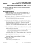
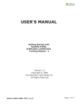
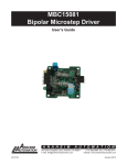
1
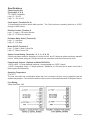
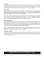
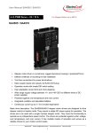
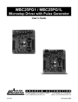
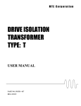
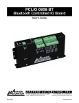
DPS32001 and DPS32PS1
Driver Pack
User’s Guide
A N A H E I M
A U T O M A T I O N
910 East Orangefair Lane, Anaheim, CA 92801
e-mail: [email protected]
L010041
(714) 992-6990 fax: (714) 992-0471
website: www.anaheimautomation.com
January 2013
DPS32 Driver Pack Features
• Bilevel Drive Operation
• 100 Watt Transformer 110/220V Operation
• 110/220V Operation
• Short Circuit Protection
• Open Motor Protection
• Fault LED
• 5 Amps/Phase Operating Current
• 3.5 Amps/Phase Output Current
• Unipolar Operation
• Half-Step and Full-Step Operation
• Motor On/Off Input
• No RFI or EMI Problems
• TTL/CMOS Compatible Inputs
• Optional +5VDC Regulated and +12 Unregulated Voltage Supply, order Model DPS32PS1
General Description
The Anaheim Automation DPS32001 is a step motor Driver Pack that can drive motors rated from 0.5 to 3.5
amp/phase (unipolar rating). DPS32001 can handle 6-lead and 8-lead motors. This Driver Pack features
a unipolar bilevel (or dual voltage) drive technique with short/open circuit protection (with a Fault LED).
Outstanding motor performance is provided by means of a Bilevel Drive technique. The DPS32001’s
open frame construction is ideal for OEM because of it’s cost-effective design.
Bilevel Drive
The basic function of a motor driver is to provide the rated motor phase current to the motor windings
in the shortest possible time. The bilevel driver uses a high voltage to get a rapid rate of current rise in
the motor windings in the least amount of time. When reaching the preset trip current, the driver turns
off the high voltage and sustains the current from the low voltage supply.
Excitation Mode Select
Users have a choice of dual-phase, full-step operation or half-step operation. Dual-phase, full-step operation occurs by energizing two phases at a time, rotating a typical motor 1.8 degrees per step. Halfstep operation occurs by alternately energizing one, and then two, phases at a time, rotating the motor
0.9 degrees per step. Full-step operation is only suggested for applications that specifically require that
mode, such as when retrofitting existing full-step systems.
Step and Direction Control
Clock and Direction, or Dual Clock operation. The Direction Input or CCW Input can be selected by
placing jumpers in the appropriate positions (see Table 2). Pulses applied to the Clock input cause the
motor to step in the clockwise direction if the Direction Input is a logic “1” or the counterclockwise direction if the Direction Input is a logic “0”. Pulses applied to the CCW Input cause the motor to step in the
counterclockwise direction. Either positive or negative going pulses may be used by setting jumpers to
the appropriate positions (See Table 2).
L010041
January 2013
+5V Power Supply (Optional, Order Model Number DPS32PS1)
This power supply is capable of suppling up to 1.0A to other devices or circuitry. The +12V unregulated
voltage may also be used for supplying current to external loads up to 1.5Amps. These outputs can only
source a combined total of 1.5 Amps maximum.
Motor On/Off Input
The Motor On/Off input allows for de-energizing a motor without disturbing the positioning logic. After reenergizing the motor, a routine can continue. This reduces motor heating and conserves power, especially
in applications where motors are stopped for long periods and no holding torque is required.
Adjusting Kick Current
By following the silk-screen markings on the side-plate, use a small screwdriver to adjust the potentiometer. Line up the arrow to the number corresponding to the motor’s rated current (amps/phase). The
kick current is preset for 40 percent over the motor’s rated amps/phase.
Dimensions
L010041
January 2013
Fault Protection
There are three types of fault detection. When a fault is detected, the driver turns off the motor current
and the red Fault LED indicates which type of fault occurred. See the Troubleshooting section for more
information.
Condition
Fault Detected
1
LED - Slow Blink
Shorted wire in the motor or cable
2
LED - Fast Blink
Open wire in the motor or cable
3
LED - ON Steady Ground fault (voltage shorted to 0V)
If the driver goes into a fault condition, the fault may be reset by turning the power OFF for at least 15
seconds, or by pulling the RESET FAULT input (terminal 4) to a Logic “0” for at least 100ms.
Function
JP1
JP2
JP3
Negative Going Clocks
1-2
X
X
Positive Going Clocks
2-3
X
X
Terminal 5 = CCW
X
1-2
X
Terminal 5 = Direction
X
2-3
X
Ground Fault Detection Enabled
X
X
2-3
Ground Fault Detection Disabled
X
X
1-2
1-2
2-3
2-3
Standard Product
Wiring Diagram and Jumper Locations
L010041
January 2013
Specifications
Control Inputs (All):
(Terminals 5, 6, 8, 9)
TTL-CMOS Compatible
Logic “0” = 0-0.8V
Logic “1” = 3.5 to 5.0V
Clock Inputs: (Terminals 5 & 6)
15 microseconds minimum pulse width required. The Clock inputs are internally pulled up to +5VDC
through a 10KU resistor.
Direction Control: (Terminal 5)
Logic “1” (open) - CW motor direction
Logic “0” - CCW motor direction
Excitation Mode Select: (Terminal 8)
Logic “1” - Half-Step
Logic “0” - Full-Step
Motor On/Off: (Terminal 9)
Logic “1” (open) - Motor Current On
Logic “0” - Motor Current Off
Output Current Rating: (Terminals 1, 2, 3, 11, 12, & 13)
5 Amps per phase maximum operating or running current, and 3.5 Amps per phase maximum standstill
current. Motor phase ratings of 0.5 Amp minimum are required to meet the minimum kick level.
Power Supply Outputs: (Optional on Model DPS32PS1)
+5VDC output: 1.5 Amps absolute maximum *(see paragraph on +5VDC Output)
+12VDC unregulated output: 1.5 Amps maximum *(Maximum of 1.5A total can be drawn from both of
these outputs simultaneously.
Operating Temperature:
0° to 60° C
The user must take into consideration where the uinit is mounted, the duty cycle of operation and the
ambient temperature. Care should be taken so that no point on the chassis exceeds 60 Degrees Celsius.
Fuse Rating:
2Amp Slow Blow, 3AG
L010041
January 2013
Troubleshooting
If a Fault occurs, reset the Fault by applying a Logic “0” to the Rest Fault Input (terminal 4) for at least
100ms (or by cycling power OFF for at least 15 seconds). After resetting, try to run the motor again. If
the driver faults again, check the conditions listed below.
Is the LED Blinking Slowly?
This indicates that the motor has a phase shorted or there is a short in the motor cable or wiring. Check
the motor and the wiring for shorts. If the driver continues to sense “shorts” after the motor and wiring are
determined to be good, then the output transistors should be checked (see below).
Is the LED Blinking Quickly?
This indicates that there is an open connection in one of the motor wires. Check the motor and the wiring
for opens. Another condition that may cause this type of fault, is when a large motor is ramped down to
quickly so that it loses it’s positioning.
Is the LED on Steadily?
This indicates that there is a ground fault-a-voltage shorted to 0VDC. This detection is useful in detecting a short-to-case in a motor when the motor’s case AND the driver’s 0VDC are both connected to earth
ground. Excessive noise on the 0VDC line may also cause the driver to sense this type of fault. This type
of fault sensing may be disabled by placing jumber JP3 in position “1-2”
NOTE: IF THE GROUND FAULT DETECTION IS DISABLED, DO NOT CONNECT THE DRIVER’S 0V
TO EARTH GROUND!
Checking Output Transistors
1. Set the multimeter to Diode Test.
2. Place the RED meter lead on (between) the Sense Resistor (labeled Rs in Figure 4).
3. Touch the BLACK meter lead to each phase (terminals 1, 2, 12, and 13).
4. This should give readings between 0.450V and 0.550V.
5. If any readings are significantly less than 0.450V, then the unit has been damaged. To send the unit
in for repair, contact the factory for an RMA#.
Torque/Speed Performance Curves
L010041
January 2013
COPYRIGHT
Copyright 2013 by Anaheim Automation. All rights reserved. No part of this publication may be reproduced,
transmitted, transcribed, stored in a retrieval system, or translated into any language, in any form or by
any means, electronic, mechanical, magnetic, optical, chemical, manual, or otherwise, without the prior
written permission of Anaheim Automation, 910 E. Orangefair Lane, Anaheim, CA 92801.
DISCLAIMER
Though every effort has been made to supply complete and accurate information in this manual, the
contents are subject to change without notice or obligation to inform the buyer. In no event will Anaheim
Automation be liable for direct, indirect, special, incidental, or consequential damages arising out
of the use or inability to use the product or documentation.
Anaheim Automation’s general policy does not recommend the use of its’ products in life support applications
wherein a failure or malfunction of the product may directly threaten life or injury. Per Anaheim Automation’s
Terms and Conditions, the user of Anaheim Automation products in life support applications assumes all
risks of such use and indemnifies Anaheim Automation against all damages.
LIMITED WARRANTY
All Anaheim Automation products are warranted against defects in workmanship, materials and construction,
when used under Normal Operating Conditions and when used in accordance with specifications. This
warranty shall be in effect for a period of twelve months from the date of purchase or eighteen months
from the date of manufacture, whichever comes first. Warranty provisions may be voided if products
are subjected to physical modifications, damage, abuse, or misuse.
Anaheim Automation will repair or replace at its’ option, any product which has been found to be defective
and is within the warranty period, provided that the item is shipped freight prepaid, with previous authorization
(RMA#) to Anaheim Automation’s plant in Anaheim, California.
TECHNICAL SUPPORT
If you should require technical support or if you have problems using any of the equipment covered by this
manual, please read the manual completely to see if it will answer the questions you have. If you need
assistance beyond what this manual can provide, contact your Local Distributor where you purchased the
unit, or contact the factory direct.
ANAHEIM AUTOMATION
L010041
January 2013