1
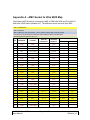
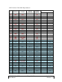
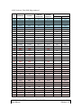
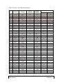
S Siilliic co on nT Tu urrn nk ke ey ye eX Xp prre es ss s Original Design Manufacturer A M C to S M A Ultra 9000 Silicon Turnkey Express 749 Miner Road • Highland Heights, Ohio 44143 Phone (440) 461-4700 • (800) 827-2650 Copyright 2006, Silicon Turnkey Express An Affiliate of RPC Electronics Inc., All Rights Reserved. AMC SMA Ultra 9000 User Manual Page 1 of 20 July 14, 2014 Revision 1.0 Revision History Rev 0.9 1.0 Date Jan 1, 2012 Jul 14, 2014 Comments Initial Release Final Release Support: Additional support information may be found at www.silicontkx.com Warranty: To assure all future engineering notifications are communicated the enclosed warranty information must be completed. AMC SMA Ultra 9000 User Manual Page 2 of 20 July 14, 2014 Revision 1.0 NOTICE The information contained within this guide is the property of Silicon Turnkey Express (STx), and except as otherwise indicated shall not be reproduced in whole or in part without the explicit written authorization of STx. The distribution of this document outside of the company is prohibited without the written authorization of STx. The following information is intended to alert the user to possible dangers and important information contained within this guide. The “WARNINGS” and “NOTES” do not eliminate these dangers. Close attention to the information supplied along with “common sense” operation is the major accident prevention measure. WARNING: Failure to follow this warning may result in bodily injury. NOTE: Failure to follow this note may result in improper results from the board. Reference Websites Below is a list of websites that can be used to obtain additional information and details that may not be fully provided in this manual. Advanced Mezzanine Card ...................................................................... www.picmg.org RapidIO………………………………………………………..……. ...............www.rapidio.org Manual Definitions There are several important definitions or abbreviations use throughout this manual. SubMiniature version A connector is referred to by the common abbreviation SMA. Advanced Mezzanine Card is referred to by the common abbreviation AMC. The ‘AMC to SMA Ultra 9000’ is referred to as Ultra 9000. See Glossary at the end of this manual for a complete set of terms and abbreviations. AMC SMA Ultra 9000 User Manual Page 3 of 20 July 14, 2014 Revision 1.0 Table of Contents Reference Websites ...................................................................................................... 3 Manual Definitions ........................................................................................................ 3 Table of Contents .......................................................................................................... 4 List of Figures ............................................................................................................... 5 List of Included Accessories ........................................................................................ 5 1.0 1.1 2.0 2.1 2.2 3.0 3.1 3.2 3.2 3.3 3.4 3.5 3.6 3.7 General Description.............................................................................................. 6 Device Placement and Functions ....................................................................................... 7 1.1.1 J01 – J90 ............................................................................................................... 7 1.1.2 LED1 (Blue) ........................................................................................................... 7 1.1.3 LED2 (Green) ........................................................................................................ 7 1.1.4 LED3 (Green) ........................................................................................................ 7 1.1.5 LED4 (Red) ............................................................................................................ 7 1.1.6 P01 – P03 Geographic Addresses ........................................................................ 7 1.1.17 P04 – AMC Socket ................................................................................................ 8 1.1.18 P05 – JTAG Connector ......................................................................................... 8 2 1.1.19 P06 – I C Header................................................................................................... 8 1.1.20 SW1 – AMC Reset ................................................................................................ 8 Hardware Design & Architecture ......................................................................... 9 General Description ............................................................................................................ 9 Physical Specifications ....................................................................................................... 9 Design Theory and Settings .............................................................................. 10 Transmit and Receive Lanes ............................................................................................ 10 Geographic Address ......................................................................................................... 10 JTAG................................................................................................................................. 11 2 I C ..................................................................................................................................... 11 Reset ................................................................................................................................ 11 Power Supply.................................................................................................................... 12 LED Indicators .................................................................................................................. 12 Synchronization Clock Interface ....................................................................................... 13 Appendix A – AMC Socket to Ultra 9000 Map ........................................................... 14 Appendix B – Connector Pin Assignments ............................................................... 19 J01 to J90 – SMA ....................................................................................................................... 19 P01– Geographic Address GA0 ................................................................................................. 19 P02– Geographic Address GA1 ................................................................................................. 19 P03– Geographic Address GA2 ................................................................................................. 19 P04 – AMC Socket ..................................................................................................................... 19 P05– JTAG ................................................................................................................................. 19 P06– I2C (IPMB) ........................................................................................................................ 19 PWR-1– Power Input (ATX) ....................................................................................................... 19 Glossary....................................................................................................................... 20 Acronyms.................................................................................................................................... 20 Definitions ................................................................................................................................... 20 AMC SMA Ultra 9000 User Manual Page 4 of 20 July 14, 2014 Revision 1.0 List of Figures Figure 1 – Ultra 9000....................................................................................................... 7 Figure 2 – Top Board Layout ........................................................................................... 7 Figure 3 – Block Diagram of Board................................................................................ 10 Figure 4 – Lane Pair Example ....................................................................................... 11 Figure 5 – Geographic Address Headers ...................................................................... 11 Figure 6 – JTAG Circuit ................................................................................................. 12 Figure 7 – I2C Circuit .................................................................................................... 12 Figure 8 – Reset Circuit................................................................................................. 12 Figure 9 – Power Supply ............................................................................................... 13 Figure 10 – LEDs .......................................................................................................... 13 Figure 11 – Synchronization Clocks .............................................................................. 14 List of Included Accessories User Manual (on CD) Schematic (on CD) AMC SMA Ultra 9000 User Manual Page 5 of 20 July 14, 2014 Revision 1.0 1.0 General Description Figure 1 – Ultra 9000 The AMC to SMA Ultra 9000 is a single AMC Carrier platform for development engineering to connect SMAs to every serdes signal on an AMC module. The Ultra 9000 includes 42 differential parts of signals, 21 transmit and 21 receive. It can be used for AMC.1 1000BASE –BX signals, AMC.3 STAT/SAS signals, AMC.4 Serial RapidIO Ports (FAT PIPE: AMC.1 x 4 PCIe; AMC.4 x S-RIO; AMC.2 10GB Base – BX4), as well as Extended FAT PIPE (disputed Ports between AMC.4 S-RIO and AMC.2 1-0G Base – BX4), and Extended Options Scope Ports per V 1.0. The carrier is powered with a standard ATX power supply. Besides providing power to the AMC socket it allows direct control to the AMC reset and Geographical Addresses, and provides connections for I2C and JTAG and synchronization clock signals. The Ultra 9000 can be manufactured with all SMAs or partial depopulated to fit the designers needs. Contact Silicon Turnkey Express for further details. AMC SMA Ultra 9000 User Manual Page 6 of 20 July 14, 2014 Revision 1.0 1.1 Device Placement and Functions This section provides a description of the connectors, jumpers, switches and main components of the board. Refer to Figure 2 for location of the devices referenced below. Additional descriptions of the switches and jumpers with their recommended settings will are in Section 3. Figure 2 –Top Board Layout 1.1.1 J01 – J90 1.1.4 Lighthorse, LTI, 26.5GHz. SMA connectors from all port signals. See Section 3.1 for connector assignments. 1.1.2 LED1 (Blue) Indicates when an AMC card is recognized in socket P4. 1.1.3 LED3 (Green) Indicates +12V is good. 1.1.5 LED4 (Red) Indicates power fault. 1.1.6 P01 – P03 Geographic Addresses Single 3 pin 0.1” header. See Section 3.2 for more details. LED2 (Green) Indicates +3.3V is good. AMC SMA Ultra 9000 User Manual Page 7 of 20 July 14, 2014 Revision 1.0 1.1.17 P04 – AMC Socket Yamaichi CN074 AMC. See Appendix A for pin out. 1.1.18 P05 – JTAG Connector Single 6 pin 0.1” header. Directly connected to Yamaichi connector. 1.1.19 P06 – I2C Header Single 3 pin 0.1” header. Directly connected to Yamaichi connector. 1.1.20 SW1 – AMC Reset Momentary switch creates an input to AMC_EN on the AMC connector when +3.3V and +12V are present and switch is actuated. AMC SMA Ultra 9000 User Manual Page 8 of 20 July 14, 2014 Revision 1.0 2.0 Hardware Design & Architecture 2.1 General Description Figure 3- Block Diagram of Board 2.2 Physical Specifications This section contains general information on the physical characteristics. Board Size ............................................................................................ 127mm x 203mm Power Requirement (to support an AMC) ................................. ATX Power Supply, 100W Operating Temperature Standard Version ..................................................................... 00 to +700C Industrial Version .................................................................. -400 to +850C Weight ....................................................................................................................... 240g AMC SMA Ultra 9000 User Manual Page 9 of 20 July 14, 2014 Revision 1.0 3.0 Design Theory and Settings This section contains information on the Ultra 9000 design and layout. It provides details of jumpers and setting available. More information on Advanced Mezzanine Card design theory is available at www.picmg.org. Information on RapidIO is available at www.com. 3.1 Transmit and Receive Lanes A Lane is a set of differential signal pairs, one pair for transmission and one pair for reception. One or more Lanes operate together to form a Link. E-keying definition of a differential pair is associated with a specific Fabric Link, Lanes [x:0]. In the Ultra 9000 all Lanes from the AMC socket to SMA connectors are matched for impedance except Lane 16. Each differential pair of Lane 16’s (transmit and receive) are impedance matched. Lane 16 as defined in R1.0 of the AMC.0 specification has been re-defined for use as TCLKC and TCLKD. See Appendix A for Lane definition and AMC socket to Ultra 9000 SMA mapping. Figure 4 – Lane Pair Example 3.2 Geographic Address Three Geographic Address (GA) pins are used to assign the address of a Module on Intelligent Platform Management Interface, IPMI. Each of the GA pins can encode three different levels; they can be connected to Logic Ground, to Management Power, or left unconnected on the Carrier to define the Geographic Address of the Module. See the AMC specifications for additional information. The Ultra 9000 connects the AMC Socket GA0, GA1 and GA2 directly to headers’ pin 2 of P1, P2 and P3 respectively. Pin 1 of the header is +3.3 Volts and pin 3 is ground. Figure 5 – Geographic Address Headers AMC SMA Ultra 9000 User Manual Page 10 of 20 July 14, 2014 Revision 1.0 3.2 JTAG This provides an industry standard method of performing manufacturing test and verification and is critical to the test of today's complex products that are often making extensive use of BGA device packages. The Ultra 9000 JTAG header is connected directly to AMC connector. Figure 6 – JTAG Circuit 3.3 I 2C IPMB is a bus made up of clock (SCL_L) and data (SDA_L) I2C signals. The Ultra 9000 provide a header for this signals that are connected directly to the AMC connector. Figure 7 – I2C Circuit 3.4 Reset The ENABLE# pin on the AMC connector is an active low input to the Module pulled up on the Module to Management Power (MP). This signal is inverted on the Module to create an MMC RESET# signal. This input indicates to the Module that the Module is fully inserted and valid states exist on all inputs to the Module. The MMC is not allowed to read the GA inputs or use the IPMB while ENABLE# is inactive. Figure 8 – Reset Circuit AMC SMA Ultra 9000 User Manual Page 11 of 20 July 14, 2014 Revision 1.0 3.5 Power Supply A standard ATX power supply provides +3.3V and +12V to a Dual Supply Hot Swap Controller, U5. The controller generates voltages to the AMC socket as well as senses the AMC and provides fault information to the Ultra 9000. Figure 9 – Power Sense Circuit 3.6 LED Indicators The Ultra 9000 four LEDs provide information from the power supply controller for AMC Insertion (Blue), +3.3V and +12V Good (Green), and AMC power supply Fault condition (Red). Figure 10 - LEDs AMC SMA Ultra 9000 User Manual Page 12 of 20 July 14, 2014 Revision 1.0 3.7 Synchronization Clock Interface The Synchronization Clock Interface provides three differential pairs for clock distribution to enable applications that require the exchange of synchronous timing information among Modules and consequently multiple boards in a Shelf. This allows Modules to source clock(s) to the system in the case where it provides a Network Interface function, or conversely to receive timing information from another Carrier Board or Module within the system. The three Synchronization Clock signals are TCLKA, TCLKB, and FCLKA, each supported by a differential pair. Figure 11 – Synchronization Clocks AMC SMA Ultra 9000 User Manual Page 13 of 20 July 14, 2014 Revision 1.0 Appendix A – AMC Socket to Ultra 9000 Map The following AMC Socket pin out maps the AMC to SMA Ultra 9000 and STx’s AMC to SMA Ultra 15000 series (standard 1U). The definitions shown are as of April 2009. AMC.2 1000BASE-BX AMC.3 SATA/SAS AMC.4 S-RIO Ports (FAT PIPE; AMC.1 x 4 PCIe; AMC.4 x4 SRIO; AMC.2 10G Base-BX4) Extended Fat Pipe; Disputed Ports Between AMC.4 SRIO and AMC.2 10G Base-BX4 Extended Options Scope Ports per V 1.0 Pin Definition Function 1 2 3 4 5 6 7 8 9 10 11 12 13 14 15 16 17 18 19 20 21 22 23 24 25 26 27 GND PWR PS1# MP GA0 RSVD6 GND RSVD8 PWR GND TX0+ TX0GND RX0+ RX0GND GA1 PWR GND TX1+ TX1GND RX1+ RX1GND GA2 PWR GND +12V_AMC AMC_PSEN +3v3_AMC GA0 NC GND NC +12V_AMC GND TX0+ TX0GND RX0+ RX0GND GA1 +12V_AMC GND TX1+ TX1GND RX1+ RX1GND GA2 +12V_AMC AMC SMA Ultra 9000 User Manual Ultra 9K Connection U5 - 10 P1 - 2 J04 -1 J13 -1 J12 -1 J03 -1 P2 - 2 J16 - 1 J09 - 1 J08 - 1 J07 -1 P3 - 2 Page 14 of 20 Insertion Sequence First First Last Second Second Second First Second First First Third Third First Third Third First Second First First Third Third First Third Third First Second First Present in Ultra 15K Extended Basic + YES YES YES YES YES YES YES YES YES YES YES YES YES YES YES YES YES YES YES YES YES YES July 14, 2014 Revision 1.0 AMC Socket to Ultra 9000 Map continued Pin Definition Function 28 29 30 31 32 33 34 35 36 37 38 39 40 41 42 43 44 45 46 47 48 49 50 51 52 53 54 55 56 57 58 59 60 61 62 63 64 GND TX2+ TX2GND RX2+ RX2GND TX3+ TX3GND RX3+ RX3GND ENABLE# PWR GND TX4+ TX4GND RX4+ RX4GND TX5+ TX5GND RX5+ RX5GND SCL_L PWR GND TX6+ TX6GND RX6+ RX6GND GND TX2+ TX2GND RX2+ RX2GND TX3+ TX3GND RX3+ RX3GND AMC_EN +12V_AMC GND TX4+ TX4GND RX4+ RX4GND TX5+ TX5GND RX5+ RX5GND SCL +12V_AMC GND TX6+ TX6GND RX6+ RX6GND AMC SMA Ultra 9000 User Manual Ultra 9K Connection J28 - 1 J27 - 1 J26 -1 J25 -1 J36 - 1 J35 - 1 J34 - 1 J33 - 1 U2 - 4 J44 -1 J43 -1 J42 -1 J41 -1 J52 -1 J51 -1 J50 -1 J49 -1 P6 - 1 J64 -1 J63 -1 J62 -1 J61 -1 Page 15 of 20 Insertion Sequence First Third Third First Third Third First Third Third First Third Third First Second First First Third Third First Third Third First Third Third First Third Third First Second First First Third Third First Third Third First Present in Ultra 15K Extended Basic + YES YES YES YES YES YES YES YES YES YES YES YES YES YES YES YES YES YES YES YES YES YES YES YES YES YES YES YES YES YES YES YES July 14, 2014 Revision 1.0 AMC Socket to Ultra 9000 Map continued Pin Definition Function 65 66 67 68 69 70 71 72 73 74 75 76 77 78 79 80 81 82 83 84 85 86 87 88 89 90 91 92 93 94 95 96 97 98 99 100 101 TX7+ TX7GND RX7+ RX7GND SDA_L PWR GND TCLKA+ TCLKAGND TCLKB+ TCLKBGND FCLKA+ FCLKAGND PS0# PWR GND GND RX8RX8+ GND TX8TX8+ GND RX9RX9+ GND TX9TX9+ GND RX10RX10+ GND TX7+ TX7GND RX7+ RX7GND SDA +12V_AMC GND TCLKA+ TCLKAGND TCLKB+ TCLKBGND FCLKA+ FCLKAGND GND +12V_AMC GND GND RX8RX8+ GND TX8TX8+ GND RX9RX9+ GND TX9TX9+ GND RX10RX10+ GND AMC SMA Ultra 9000 User Manual Ultra 9K Connection Insertion Sequence J72 -1 J71 -1 Third Third First Third Third First Second First First Third Third First Third Third First Third Third First Last First First First Third Third First Third Third First Third Third First Third Third First Third Third First J70 -1 J69 -1 P6 - 2 J80 -1 J79 - 1 J78 - 1 J77 - 1 J86 - 1 J85 -1 J90 J89 J88 J87 J84 J83 J82 J81 J76 J75 Page 16 of 20 Present in Ultra 15K Extended Basic + YES YES YES YES YES YES YES YES YES YES YES YES YES YES YES YES YES YES YES YES YES YES YES YES YES YES YES YES July 14, 2014 Revision 1.0 AMC Socket to Ultra 9000 Map continued Pin Definition Function 102 103 104 105 106 107 108 109 110 111 112 113 114 115 116 117 118 119 120 121 122 123 124 125 126 127 128 129 130 131 132 133 134 135 136 137 138 TX10TX10+ GND RX11RX11+ GND TX11TX11+ GND RX12RX12+ GND TX12TX12+ GND RX13RX13+ GND TX13TX13+ GND RX14RX14+ GND TX14TX14+ GND RX15RX15+ GND TX15TX15+ GND RX16RX16+ GND TX16- TX10TX10+ GND RX11RX11+ GND TX11TX11+ GND RX12RX12+ GND TX12TX12+ GND RX13RX13+ GND TX13TX13+ GND RX14RX14+ GND TX14TX14+ GND RX15RX15+ GND TX15TX15+ GND RX16RX16+ GND TX16- AMC SMA Ultra 9000 User Manual Ultra 9K Connection Insertion Sequence J74 J73 Third Third First Third Third First Third Third First Third Third First Third Third First Third Third First Third Third First Third Third First Third Third First Third Third First Third Third First Third Third First Port J68 J67 J66 J65 J60 J59 J58 J57 J56 J55 J54 J53 J48 J47 J46 J45 J40 J39 J38 J37 J32 J31 J30 Page 17 of 20 Present in Ultra 15K Extended Basic + YES YES YES YES YES YES YES YES YES YES YES YES YES YES YES YES YES YES YES YES YES YES YES YES YES July 14, 2014 Revision 1.0 AMC Socket to Ultra 9000 Map continued Pin Definition Function 139 140 141 142 143 144 145 146 147 148 149 150 151 152 153 154 155 156 157 158 159 160 161 162 163 164 165 166 167 168 169 170 TX16+ GND RX17RX17+ GND TX17TX17+ GND RX18RX18+ GND TX18TX18+ GND RX19RX19+ GND TX19TX19+ GND RX20RX20+ GND TX20TX20+ GND TCK TMS TRST# TDO TDI GND TX16+ GND RX17RX17+ GND TX17TX17+ GND RX18RX18+ GND TX18TX18+ GND RX19RX19+ GND TX19TX19+ GND RX20RX20+ GND TX20TX20+ GND TCK TMS TRST# TDO TDI GND M1 to M8 M1 to M8 AMC SMA Ultra 9000 User Manual Ultra 9K Connection Insertion Sequence J29 Third First Port Third First Third Third First Third Third First Third Third First Third Third First Third Third First Third Third First Third Third First Second Second Second Second Second First J24 J23 J22 J21 J20 J19 J18 J17 J06 J15 J14 J05 J02 J01 J11 J10 P5 - 6 P5 - 5 P5 - 4 P5 - 3 P5 - 2 Page 18 of 20 Present in Ultra 15K Extended YES Basic + YES YES YES YES YES YES YES YES YES YES YES YES YES YES YES YES YES YES YES YES YES YES YES YES YES YES July 14, 2014 Revision 1.0 Appendix B – Connector Pin Assignments J01 to J90 – SMA Lighthorse, LTI, 26.5 GHz, Vertical See Appendix A for pin connection P06– I2C (IPMB) 3 pin header 0.1 Pin No 1 2 3 P01– Geographic Address GA0 3 pin header 0.1 Pin No 1 2 3 Description +3.3V GA0 GND Pin No 1 2 3 4 5 6 7 8 9 10 11 12 13 14 15 16 17 18 19 20 Description 1 +3.3V 2 GA1 3 GND P03– Geographic Address GA2 3 pin header 0.1 Pin No Description 1 +3.3V 2 GA2 3 GND P04 – AMC Socket Yamaichi See Appendix A for pin out P05– JTAG 6 pin header 0.1 Pin No 1 2 3 4 5 6 SCL SDA GND PWR-1– Power Input (ATX) Molex 39-01-2200 P02– Geographic Address GA1 3 pin header 0.1 Pin No Description Description +3.3V +3.3V GND NC GND NC GND NC NC +12v +3.3v NC GND GND GND GND GND NC NC NC Description GND TDI TDO TST# TMS TCK AMC SMA Ultra 9000 User Manual Page 19 of 20 July 14, 2014 Revision 1.0 Glossary Here is a list of terms, acronyms and definitions that may be incorporated in this manual. Acronyms AMC ........................................................................................................ Advanced Mezzanine Card ATAC ........................................................ Advanced Telecommunications Computing Architecture ATX ..................................................... Advanced Technology Extended (mother board form factor) CPLD ..................................................................................... Complex Programmable Logic Device CPU ............................................................................................................... Central Processor Unit DMA ............................................................................................................... Direct Memory Access DSP ............................................................................................................. Digital Signal Processor FRU ............................................................................................................. Field Replaceable Units GA ......................................................................................................................Geographic Address GIGE ........................................................................................................................ Gigabit Ethernet IPMB ....................................................................................... Intelligent Platform Management Bus IPMI ................................................................................ Intelligent Platform Management Interface JTAG ........................................................................................................... Test Port per IEEE 1149 MMC ................................................................................................ Module Management Controller MP ..................................................................................................................... Management Power OOB ................................................................................................................................ Out of Band PCIe ............................................................................ Peripheral Component Interconnect Express PICMG ...................................................................... PCI Industrial Computer Manufacturers Group PMC .................................................................................................................. PCI Mezzanine Card RAM ........................................................................................................... Random Access Memory SCL .....................................................................................Serial Clock (use with I2C Bus or IPMB) SDA ..................................................................................... Serial Data (use with I2C Bus or IPMB) S-RIO (SRIO) .............................................................................................................. Serial RapidIO TCK .........................................................................................................Test Clock (use with JTAG) TDI ....................................................................................................... Test Data In (use with JTAG) TDO .................................................................................................. Test Data Out (use with JTAG) TMS ............................................................................................ Test Mode Select (use with JTAG) TST# (TRST) ................................................................................ Test Reset Input (use with JTAG) Definitions AMC.x Fat Pipe Lane Link Port SerDes Shelf AdvancedMC is targeted to requirements for the next generation of "carrier grade" communications equipment. This series of specifications are designed to work on any carrier card and controlled by over 100 companies known as the PCI Industrial Computers Manufactures Group, PICMG. A Fat Pipe is a data transmission circuit or network that is capable of carrying large amounts of data without significantly degrading the speed of transmission. A set of differential signal pairs, one pair for transmission and one pair for reception. One or more Lanes operate together to form a Link. A group of Lanes which operate together to connect two devices; the number of Lanes used is negotiated. A set of differential signal pairs, one pair for transmission and one pair for reception. (serializers/deserializers) are devices that can take wide bit-width, single-ended signal buses and compress them to a few, typically one, differential signal that switches at a much higher frequency rate than the wide single-ended data bus. The Shelf consists of the Subrack, Backplane, Front Boards, cooling deices, RTMs, power suppliers, etc. Also historically known as a chassis. AMC SMA Ultra 9000 User Manual Page 20 of 20 July 14, 2014 Revision 1.0