1
4-axis Motion Control Module
User Manual
(I-8094 and I-8094F)
(Version 2.5)
Macro Function Library in C++ for
WinCon and I-8000 series PAC controllers
ICPDAS
1
I-8094 Software User Manual
Warranty
All products manufactured by ICPDAS Inc. are warranted against defective
materials for a period of one year from the date of delivery to the original
purchaser.
Warning
ICPDAS Inc. assumes no liability for damages consequent to the use of this
product. ICPDAS Inc. reserves the right to change this manual at any time without
notice. The information furnished by ICPDAS Inc. is believed to be accurate and
reliable. However, no responsibility is assumed by ICPDAS Inc. for its use, or for
any infringements of patents or other rights of third parties resulting from its use.
Copyright
Copyright 1997-2009 by ICPDAS Inc., LTD. All rights reserved worldwide.
Trademark
The names used for identification only maybe registered trademarks of their
respective companies.
License
The user can use, modify and backup this software on a single machine. The
user may not reproduce, transfer or distribute this software, or any copy, in whole
or in part.
ICPDAS
2
I-8094 Software User Manual
INDEX
1 PREFACE ............................................................................ 6
1.1 Introduction................................................................................................ 6
1.2 Macro functions ......................................................................................... 6
1.3 Funciton description .................................................................................. 7
2 BASIC SETTINGS.............................................................. 8
2.1 Code numbers for axes .............................................................................. 8
2.2 Registration of Modules and getting the LIB version ............................ 8
2.3 Resetting Module ..................................................................................... 11
2.4 Pulse Output Mode Setting ..................................................................... 11
2.5 Setting the Maximum Speed ................................................................... 13
2.6 Setting the Active Level of the Hardware Limit Switches ................... 13
2.7 Setting the Motion Stop Method When Limit Switch Is Sensed ......... 15
2.8 Setting the Trigger Level of the NHOME Sensor ................................. 15
2.9 Setting Trigger Level of the Home sensor ............................................. 16
2.10 Setting and Clearing the Software Limits ........................................... 16
2.11 Setting the Encoder Related Parameters ............................................. 18
2.12 Setting the Servo Driver (ON/OFF) ..................................................... 18
2.13 Setting the SERVO ALARM Function ................................................ 20
2.14 Setting the Active Level of the In-Position Signals ............................. 20
2.15 Setting the Time Constant of the Digital Filter................................... 22
2.16 Position Counter Variable Ring............................................................ 23
2.17 Triangle prevention of fixed pulse driving .......................................... 25
2.18 External Pulse Input.............................................................................. 26
2.18.1 Handwheel (Manual Pulsar) Driving ..............................................................26
2.18.2 Fixed Pulse Driving Mode ..............................................................................28
2.18.3 Continuous Pulse Driving Mode....................................................................29
2.18.4 Disabling the External Signal Input Functions.............................................30
2.19 Configure hardware with pre-defined configuration file................... 31
3 READING AND SETTING THE REGISTERS............. 32
3.1 Setting and Reading the Command Position (LP)................................ 32
3.2 Setting and Reading the Encoder Counter............................................ 33
3.3 Reading the Current Velocity ................................................................. 34
3.4 Reading the Current Acceleration.......................................................... 34
3.5 Reading the DI Status .............................................................................. 35
3.6 Reading and Clearing the ERROR Status ............................................ 37
4 FRNET FUNCTIONS (FOR I8094F ONLY).................. 39
ICPDAS
3
I-8094 Software User Manual
4.1 Read FRnet DI Signals ............................................................................ 39
4.2 Write data to FRnet DO .......................................................................... 40
5 AUTO HOMING ............................................................... 41
5.1 Setting the Homing Speed ....................................................................... 43
5.2 Using an Limit Switch as the HOME sensor......................................... 43
5.3 Setting the Homing Mode........................................................................ 44
5.3.1 Step 1: High-Speed Near Home Search ..........................................................44
5.3.2 Step 2: Low-Speed Home Search ....................................................................45
5.3.3 Step 3: Low-Speed Z-phase Search ................................................................46
5.3.4 Step 4: High-Speed Offset Drive ......................................................................47
5.4 Starting the Homing Sequence ............................................................... 49
5.5 Waiting for the Homing sequence to be Completed ............................. 49
6 GENERAL MOTION CONTROL.................................. 50
6.1 Independent Axis Motion Control.......................................................... 50
6.1.1 Setting the Acceleration/Deceleration Mode ..................................................50
6.1.2 Setting the Start Speed.....................................................................................53
6.1.3 Setting the Desired Speed................................................................................54
6.1.4 Setting the Acceleration ...................................................................................54
6.1.5 Setting the Deceleration ...................................................................................56
6.1.6 Setting the Acceleration Rate ..........................................................................57
6.1.7 Setting the Deceleration Rate ..........................................................................58
6.1.8 Setting the Value of the Remaining Offset Pulses .........................................59
6.1.9 Fixed Pulse Output ...........................................................................................60
6.1.10 Continuous Pulse Output...............................................................................61
6.2 Interpolation Commands ........................................................................ 62
6.2.1 Assigning the Axes for Interpolation...............................................................62
6.2.2 Setting the Speed and Acc/Dec Mode for Interpolation ................................63
6.2.3 Setting the Vector Starting Speed ...................................................................68
6.2.4 Setting the Vector Speed..................................................................................69
6.2.5 Setting the Vector Acceleration .......................................................................69
6.2.6 Setting the Vector Deceleration Value.............................................................70
6.2.7 Setting the Vector Acceleration Rate ..............................................................71
6.2.8 Setting the Vector Deceleration Rate ..............................................................72
6.2.9 Setting the Number of the Remaining Offset Pulses .....................................73
6.2.10 2-Axis Linear Interpolation Motion ................................................................74
6.2.11 3-axis Linear Interpolation Motion.................................................................75
6.2.12 2-Axis Circular Interpolation Motion (an Arc)...............................................76
6.2.13 2-Axis Circular Interpolation Motion (a Complete Circle) ...........................78
6.3 Synchronous Actions................................................................................ 80
6.3.1 Setting the Synchronous Action......................................................................80
6.3.2 Setting the COMPARE value ............................................................................84
6.3.3 Get the LATCH value.........................................................................................86
6.3.4 Set the PRESET data for synchronous action................................................86
ICPDAS
4
I-8094 Software User Manual
6.4 Continuous Interpolation ........................................................................ 87
6.4.1 2-Axis Rectangular Motion ...............................................................................87
6.4.2 2-Axis Continuous Linear Interpolation..........................................................89
6.4.3 3-Axis Continuous Linear Interpolation..........................................................91
6.4.4 Mixed Linear and Circular 2-axis motions in Continuous Interpolation ......93
6.4.5 Multi-Segment Continuous Interpolation (Using Array) ................................96
6.4.6 3-Axis Helical Motion ........................................................................................98
6.4.7 2-Axis Ratio Motion.........................................................................................100
6.5 Set the Interrupt Factors....................................................................... 102
6.5.1 Set the Interrupt Factors ................................................................................102
6.5.2 Interrupt Disabled ...........................................................................................105
6.5.3 Read the Interrupt Occurrence ......................................................................106
6.6 Other functions....................................................................................... 107
6.6.1 Holding the Driving Command ......................................................................107
6.6.2 Release the Holding Status, and Start the Driving.......................................108
6.6.3 Waiting until the Motion Is Completed ..........................................................109
6.6.4 Stopping the Axes...........................................................................................110
6.6.5 Clear the Stop Status ......................................................................................114
6.6.6 End of Interpolation ........................................................................................114
ICPDAS
5
I-8094 Software User Manual
1 Preface
1.1 Introduction
This manual provides complete and detailed description of i8094 functions for
users to develop programs for their control of automatic equipments. Many
examples are included in this manual for reference to write efficient
application programs.
This manual includes six chapters and two appendices. This chapter gives a
brief description of this manual. Chapter 2 to 6 is the explanations of macro
functions (MF).
The functions defined in DLL file are explained here. This DLL can be used on
different developing software platforms, such as eVC++, VB.net, and C#.net,
and different OS systems ( MiniOS7 / WinCE / Linux).
1.2 Macro functions
Macro functions provide a set of much easy-to-use functions that simplify the
programming for users. Some necessary settings, such as speed range and
deceleration point, are calculated inside those functions to ease the loading of
users on having to understand the motion chip. Some useful costumed
functions are provided for users to develop applications efficiently.
ICPDAS
6
I-8094 Software User Manual
1.3 Funciton description
All functions are listed in following form:
z Function_name (parameter1, parameter2, …)
Description:
Explanation of this function.
Parameters:
Definitions of the parameters and how to use them.
Return:
The return value of this function.
Example:
Simple example program in C++.
Remark:
Comments.
ICPDAS
7
I-8094 Software User Manual
2 Basic Settings
2.1 Code numbers for axes
The axis assignments follow the definitions listed below: X=1, Y=2, Z=4, and
U=8. If X and Y axes are assigned simultaneously, then the code number is 3. In
a similar way, AXIS_YZ = 2+4 =0x6; and AXIS_XYZU = 1+2+4+8 = 0xf. An
assignment for either single axis or multiple axes at the same time is possible.
Available axis code numbers are listed below. The type of the axis argument used
in the functions is defined as WORD.
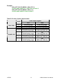
Table 2-1 Axis assignments and their corresponding codes
Axis
X
Y
Z
U
XY
XZ
XU
YZ
Code
0x1
0x2
0x4
0x8
0x3
0x5
0x9
0x6
Name
AXIS_X
AXIS_Y
AXIS_Z
AXIS_U
AXIS_XY
AXIS_XZ
AXIS_XU
AXIS_YZ
Axis
YU
ZU
XYZ
XYU
XZU
YZU
XYZU
Code
0xa
0xc
0x7
0xb
0xd
0xe
0xf
Name
AXIS_YU
AXIS_ZU
AXIS_XYZ
AXIS_XYU
AXIS_XZU
AXIS_YZU
AXIS_XYZU
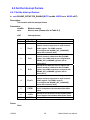
2.2 Registration of Modules and getting the LIB version
z BYTE i8094MF_REGISTRATION(BYTE cardNo, BYTE slot)
Description:
This function registers a module that is installed in slot number, slot, by
assigning a card number. Registration must be performed for each I-8094
motion control module before other functions are called. After registration,
each module can be identified by its corresponding module number.
Parameters:
cardNo:
slot:
Module number
Slot number
for I-8000: 0~7
for WinCon-8000: 1~7
Return:
YES
NO
ICPDAS
Normal
Abnormal
8
I-8094 Software User Manual
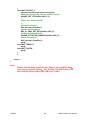
Example:
//================= for WinCon-8000 ==================
//set each module number the same as the slot number, respectively.
//(slot1 ~ slot7)
BYTE cardNo;
BYTE slot;
int Found = 0;
for (slot = 1; slot < 8; slot++)
{
cardNo = slot;
if (i8094MF_REGISTRATION(cardNo, slot) == YES)
{ //slot number begins from 1.
//if a module is found, then it is registered as its slot number.
i8094MF_RESET_CARD(cardNo);
Found++;
}
}
if (Found == 0)
{
//if Wincon cannot find any I-8094 module,
//please add codes to handle the exception here.
return;
}
//=================== for I-8000 ===================
//set the module number the same as the slot number, respectively.
//(slot1 ~ slot7)
BYTE cardNo;
BYTE slot;
int Found = 0;
for (slot = 0; slot < 8; slot++)
{
cardNo = slot + 1;
//slot number begins from 0, but module number begin from 1.
if (i8094MF_REGISTRATION(cardNo, slot) == YES)
{
//if a module is found, then it is registered by giving a number.
i8094MF_RESET_CARD(cardNo);
Found++;
}
}
if (Found == 0)
{
//if Wincon cannot find any I-8094 module,
//please add codes to handle the exception here.
return;
ICPDAS
9
I-8094 Software User Manual
}
z WORD i8094MF_GET_VERSION(void)
Description:
Read the version of current i8094 library.
Parameters:
cardNo:
Module number
Return:
Version code:
including information of the year and the month:
0x0000 ~ 0x9999
Example:
WORD VER_No;
VER_No = i8094MF_GET_VERSION();
//Read the version code of i8094.dll
Remark:
If the return value is 0x0607
06 : the year is 2006
07: the month is July.
ICPDAS
10
I-8094 Software User Manual
2.3 Resetting Module
z void i8094MF_RESET_CARD(BYTE cardNo)
Description:
This function resets module using a software command.
Parameters:
cardNo:
Module number
Return:
None
Example:
i8094MF_RESET_CARD(1);
//Reset module 1.
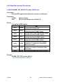
2.4 Pulse Output Mode Setting
z void i8094MF_SET_PULSE_MODE(BYTE cardNo, WORD axis, BYTE nMode)
Description:
This function sets the pulse output mode as either CW/CCW or PULSE/DIR
for the assigned axes and their direction definition.
Parameters:
cardNo:
axis:
nMode:
Module number
Axis or axes (Please refer to Table 2-1)
Assigned mode (Please refer to Table 2-2)
Return:
None
ICPDAS
11
I-8094 Software User Manual
Example:
i8094_SET_PULSE_MODE(1, AXIS_XYZ, 2);
//set the pulse mode of X, Y, and Z axes as mode 2
i8094_SET_PULSE_MODE(1, AXIS_U, 3);
//set the pulse mode of U axis as mode 3
Table 2-2 A List of pulse output modes
mode
CW / CCW
PULSE / DIR
ICPDAS
Pulse output signals
nPP
nPM
0
CW (rising edge)
CCW (rising edge)
1
CW (falling edge)
CCW (falling edge)
2
PULSE (rising edge)
3
PULSE (falling edge)
4
PULSE (rising edge)
5
PULSE (falling edge)
12
DIR
(LOW:+dir/ HIGH:-dir)
DIR
(LOW:+dir/ HIGH:-dir)
DIR
(HIGH:+dir/ LOW:-dir)
DIR
(HIGH:+dir/ LOW:-dir)
I-8094 Software User Manual
2.5 Setting the Maximum Speed
z void i8094MF_SET_MAX_V(BYTE cardNo, WORD axis, DWORD data)
Description:
This function sets the maximum rate for the output pulses (speed). A
larger value will cause a rougher resolution. For example, when the
maximum speed is set as 8000 PPS, the resolution is 1 PPS; when the
maximum speed is set as 16000 PPS, the resolution is 2 PPS; when
maximum speed is set as 80000 PPS, the resolution is 10 PPS, etc. The
maximum value is 4,000,000 PPS, which means the resolution of speed
will be 500 PPS. This function change the resolution of speed to reach the
desired maximum speed. Since the scale in hardware is changed, other
parameters will be influenced too, such as the starting speed, the
acceleration, and the jerk. It is recommended to set the maximum speed
value as a integral multiplier of 8000.
Parameters:
cardNo:
axis:
data:
Module number
Axis or axes (Please refer to Table 2-1)
The assigned maximum speed of each axis when the
controller performs an interpolation motion. However, setting
the value of axis 1 is enough. For axis 1, the maximum value
is 4,000,000 PPS.
Return:
None
Example:
i8094MF_SET_MAX_V(1, AXIS_XY, 200000L);
//The maximum speed for the X and Y axes of module 1 is 200KPPS.
//The resolution of the speed will be 200000/8000 = 25 PPS.
2.6 Setting the Active Level of the Hardware Limit Switches
z void i8094MF_SET_HLMT(BYTE cardNo, WORD axis, BYTE nFLEdge,
BYTE nRLEdge)
Description:
This function sets the active logic level of the hardware limit switch inputs.
Parameters:
cardNo:
axis:
ICPDAS
Module number
Axis or axes (Please refer to Table 2-1)
13
I-8094 Software User Manual
nFLEdge:
nRLEdge:
Active level setting for the forward limit switch.
0 = low active; 1 = high active
Active level setting for the reverse limit switch.
0 = low active; 1 = high active
Return:
None
Example:
i8094MF_SET_HLMT(1, AXIS_XYZU, 0, 0);
//set all the trigger levels as low-active for all limit switches
//on module 1.
ICPDAS
14
I-8094 Software User Manual
2.7 Setting the Motion Stop Method When Limit Switch Is
Sensed
z void i8094MF_LIMITSTOP_MODE (BYTE cardNo, WORD axis, BYTE nMode)
Description:
This function sets the motion stop mode of the axes when the
corresponding limit switches are detected.
Parameters:
cardNo:
axis:
nMode:
Module number
Axis or axes (Please refer to Table 2-1)
0: stop immediately; 1: decelerating to stop
Return:
None
Example:
i8094MF_LIMITSTOP_MODE(1, AXIS_X, 0);
//set X axis to stop immediately if any limit switch on X axis is triggered.
2.8 Setting the Trigger Level of the NHOME Sensor
z void i8094MF_SET_NHOME(BYTE cardNo, WORD axis, BYTE nNHEdge)
Description:
This function sets the trigger level of the near home sensor (NHOME).
Parameters:
cardNo:
axis:
nNHEdge:
Module number
Axis or axes (Please refer to Table 2-1)
Active level setting for the near home sensor.
0 = low active;
1 = high active
Return:
None
Example:
i8094MF_SET_NHOME(1, AXIS_XY, 0);
//set the trigger level of NHOME of X and Y axes on module 1 to be active low.
ICPDAS
15
I-8094 Software User Manual
2.9 Setting Trigger Level of the Home sensor
z void i8094MF_SET_HOME_EDGE(BYTE cardNo, WORD axis, BYTE nHEdge)
Description:
This function sets the trigger level of the home sensor (HOME).
Parameters:
cardNo:
axis:
nHEdge:
Module number
Axis or axes (Please refer to Table 2-1)
Active level setting for the home sensor.
0 = low active; 1 = high active
Return:
None
Example:
i8094MF_SET_HOME_EDGE(1, AXIS_XYZU, 1);
//set the trigger level as high active for all home sensors on module 1.
2.10 Setting and Clearing the Software Limits
z void i8094MF_SET_SLMT(BYTE cardNo, WORD axis, long dwFL, long dwRL,
BYTE nType)
Description:
This function sets the software limits.
Parameters:
cardNo:
axis:
dwFL:
dwRL:
nType:
Module number
Axis or axes (Please refer to Table 2-1)
Value of the forward software limit
(-2,147,483,648 ~ +2,147,483,647)
Value of the reverse software limit
(-2,147,483,648 ~ +2,147,483,647)
Position counter to be compared:
0 = logical position counter (LP), i.e., the command position
1 = encoder position counter (EP), i.e., the real position
Return:
None
ICPDAS
16
I-8094 Software User Manual
Example:
i8094MF_SET_SLMT(1, AXIS_XYZU, 20000, -3000, 0);
//set the forward software limit as 20000 and the reverse
//software limit as -3000 for all axes on module 1.
z void i8094MF_CLEAR_SLMT(BYTE cardNo, WORD axis)
Description:
This function clears the software limits.
Parameters:
cardNo:
axis:
Module number
Axis or axes (Please refer to Table 2-1)
Return:
None
Example:
i8094MF_CLEAR_SLMT(1, AXIS_XYZU);
//clear the software limits for all axes on module 1.
ICPDAS
17
I-8094 Software User Manual
2.11 Setting the Encoder Related Parameters
z void i8094MF_SET_ENCODER(BYTE cardNo, WORD axis, BYTE nMode,
BYTE nDivision, BYTE nZEdge)
Description:
This function sets the encoder input related parameters.
Parameters:
cardNo:
axis:
nMode:
nDivision:
nZEdge:
Module number
Axis or axes (Please refer to Table 2-1)
Encoder input type: 0 = A quad B; 1 = up/down
Division setting for A quad B input signals:
0 = 1/1
1 = 1/2
2 = 1/4
Sets the trigger level for the Z phase
0 = low active; 1 = high active
Return:
None
Example:
i8094MF_SET_ENCODER(1, AXIS_XYZU, 0, 0, 0);
//set the encoder input type as A quad B; the division is 1;
//and the Z phase is low active.
2.12 Setting the Servo Driver (ON/OFF)
z void i8094_SERVO_ON(BYTE cardNo, WORD axis)
Description:
This function outputs a DO signal (ENABLE) to enable the motor driver.
Parameters:
cardNo:
axis:
Module number
Axis or axes (Please refer to Table 2-1)
Return:
None
Example:
i8094_SERVO_ON(1, AXIS_XYZU);
ICPDAS
18
I-8094 Software User Manual
//enables all drivers on module 1.
z void i8094_SERVO_OFF(BYTE cardNo, WORD axis)
Description:
This function outputs a DO signal (ENABLE) to disable the motor driver.
Parameters:
cardNo:
axis:
Module number
Axis or axes (Please refer to Table 2-1)
Return:
None
Example:
i8094_SERVO_OFF(1, AXIS_XYZU);
//disables all drivers on module 1.
ICPDAS
19
I-8094 Software User Manual
2.13 Setting the SERVO ALARM Function
z void i8094MF_SET_ALARM(BYTE cardNo, WORD axis, BYTE nMode,
BYTE nAEdge)
Description:
This function sets the ALARM input signal related parameters.
Parameters:
cardNo:
axis:
nMode:
nAEdge:
Module number
Axis or axes (Please refer to Table 2-1)
Mode: 0 = disable ALARM function;
1 = enable ALARM function
Sets the trigger level
0 = low active; 1 = high active
Return:
None
Example:
i8094MF_SET_ALARM(1, AXIS_ZU, 1, 0);
//enable the ALARM for the Z and U axes on module 1 and set them
//as low-active.
2.14 Setting the Active Level of the In-Position Signals
z void i8094MF_SET_INPOS(BYTE cardNo, WORD axis, BYTE nMode,
BYTE nIEdge)
Description:
This function sets the INPOS input signal related parameters.
Note: Sometimes, this signal is used to connect the SERVO READY input
signal. Users should take care of what signal the daughter board is
wired.
Parameters:
cardNo:
ICPDAS
Module number
20
I-8094 Software User Manual
axis:
nMode:
nlEdge:
Axis or axes (Please refer to Table 2-1)
Mode: 0 = disable INPOS input;
1 = enable INPOS input
Set the trigger level
0 = low active; 1 = high active
Return:
None
Example:
i8094MF_SET_INPOS(1, AXIS_X, 1, 0);
//enable the INPOS function of the X axis on module 1 and set it to be low-active.
Note:
ICPDAS
Please refer to the example shown in Fig. 2.12 for wiring of the general DI
input.
21
I-8094 Software User Manual
2.15 Setting the Time Constant of the Digital Filter
z void i8094MF_SET_FILTER(BYTE cardNo, WORD axis, WORD FEn, WORD FLn)
Description:
This function selects the axes and sets the time constant for digital filters of
the input signals.
Parameters:
cardNo:
axis:
FEn:
Module number
Axis or axes (Please refer to Table 2-1)
Enabled filters. The sum of the code numbers (0~31) are used
to select input signals. Please refer to the following table.
Code number
1
2
4
8
16
FLn:
Enabling filters
EMG, nLMTP, nLMTM, nIN0, nIN1
nIN2
nINPOS, nALARM
nEXPP, nEXPM, EXPLSN
nIN3
Sets the filter time constant (0~7) as follows.
Code Removable max. noise width Input signal delay time
0
1.75 μ SEC
2 μ SEC
1
224 μ SEC
256 μ SEC
2
448 μ SEC
512 μ SEC
3
896 μ SEC
1.024mSEC
4
1.792mSEC
2.048mSEC
5
3.584mSEC
4.096mSEC
6
7.168mSEC
8.192mSEC
7
14.336mSEC
16.384mSEC
Return:
None
Example:
i8094MF_SET_FILTER(1, AXIS_XYZU, 21, 3);
//set the filter time constants of X, Y, Z, and U axes as 1.024mSEC.
//These filters include EMG, nLMTP, nLMTM, nIN0, nIN1, nINPOS, nALARM,
//and nIN3.
//(21 = 1+4+16)
1: EMG + nLMP + nLMPM + nIN0 + nIN1;
//
4: nINPOS + nALARM;
//
16: nIN3.
Note:
ICPDAS
The default wiring design is: nIN0 is connected to the NEAR HOME
(NHOME) sensors; nIN1 is connected to the HOME sensors; and nIN2 is
connected to the index of Encoder input (Z phase).
22
I-8094 Software User Manual
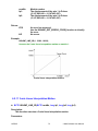
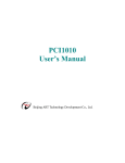
2.16 Position Counter Variable Ring
z void i8094MF_VRING_ENABLE(BYTE cardNo, WORD axis, DWORD nVRing)
Description:
This function enables the linear counter of the assigned axes as variable ring
counters.
Parameters:
cardNo:
axis:
nVRing:
Module number
Axis or axes (Please refer to Table 2-1)
Maximum value of the ring counter
(1 ~ 0xffffffff)
Return:
None
Example:
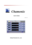
i8094MF_ VRING_ENABLE(1, AXIS_X, 9999);
//set the X axis of module 1 to be a ring counter. The encoder
//values will be 0 to 9999.
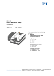
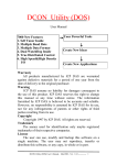
The encoder value is 0 to 9999. When the
counter value reach 9999, an adding pulse
will cause the counter to reset to 0. When the
counter value is 0, a lessening pulse will let
the counter set to 9999.
Max. ring encoder value = 9999
Note:
ICPDAS
1. This function will set the LP and EP simultaneously.
2. If this function is enabled, the software limit function cannot be used.
23
I-8094 Software User Manual
z void i8094MF_VRING_DISABLE(BYTE cardNo, WORD axis)
Description:
This function disables the variable ring counter function.
Parameters:
cardNo:
axis:
Module number
Axis or axes (Please refer to Table 2-1)
Return:
None
Example:
i8094MF_ VRING_DISABLE(1, AXIS_X);
//disable the ring counter function for the X axis
//on module 1.
ICPDAS
24
I-8094 Software User Manual
2.17 Triangle prevention of fixed pulse driving
z
void i8094MF_AVTRI_ENABLE (BYTE cardNo, WORD axis)
Description:
This function prevents a triangle form in linear acceleration (T-curve) fixed
pulse driving even if the number of output pulses is low.
Parameters:
cardNo:
axis:
Module number
Axis or axes (Please refer to Table 2-1)
Return:
None
Example:
i8094MF_ AVTRI_ENABLE(1, AXIS_X);
//set the X axis of module 1 not to generate a triangle form in its speed profile.
z
void i8094MF_AVTRI_DISABLE (BYTE cardNo, WORD axis)
Description:
This function disable the function that prevents a triangle form in linear
acceleration fixed pulse driving.
Parameters:
cardNo:
axis:
Module number
Axis or axes (Please refer to Table 2-1)
Return:
None
Example:
i8094MF_ AVTRI_DISABLE(1, AXIS_X);
//enable the X axis of module 1 to generate a triangle form in its
//speed profile if the pulse number for output is too low.
ICPDAS
25
I-8094 Software User Manual
2.18 External Pulse Input
2.18.1 Handwheel (Manual Pulsar) Driving
z void i8094MF_EXD_MP(BYTE cardNo, WORD axis, long data)
Description:
This function outputs pulses according to the input pulses from a handwheel.
Parameters:
cardNo:
axis:
data:
Module number
Axis or axes (Please refer to Table 2-1.)
The axis can be either X, Y, Z, or U.
Gain (a multiplier)
Return:
None
Example:
i8094MF_EXD_MP(1, AXIS_X, 1);
//Each time the handwheel inputs a pulse to the X axis
//on module 1, the controller will output 1 pulses to the motor driver.
ICPDAS
26
I-8094 Software User Manual
i8094MF_EXD_MP(1, AXIS_X, 2);
//Each time the handwheel inputs a pulse to the X axis
//on module 1, the controller will output 2 pulses to the motor driver.
ICPDAS
27
I-8094 Software User Manual
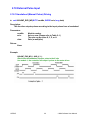
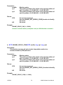
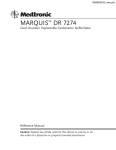
2.18.2 Fixed Pulse Driving Mode
z void i8094MF_EXD_FP(BYTE cardNo, WORD axis, long data)
Description:
This function outputs fixed pulses according to the trigger input (the falling
edge of the nEXP+ signal) from a handwheel.
Parameters:
cardNo:
axis:
data:
Module number
Axis or axes (Please refer to Table 2-1.)
The axis can be either X, Y, Z, or U.
Number of fixed pulses.
Return:
None
Example:
i8094MF_EXD_FP(1, AXIS_X, 5);
//Each time the controller detects a falling edge of an XEXP+
//signal, it will output 5 pulses to the X axis.
Example of fixed pulse driving using an external signal
ICPDAS
28
I-8094 Software User Manual
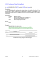
2.18.3 Continuous Pulse Driving Mode
z void i8094MF_EXD_CP(BYTE cardNo, WORD axis, long data)
Description:
The controller will continuously output pulses in positive direction if the
falling edge of nEXP+ signal from a handwheel is detected. Conversely, it will
continuously output pulses in negative direction if the falling edge of nEXP- signal
is detected.
Parameters:
cardNo:
axis:
data:
Module number
Axis or axes (Please refer to Table 2-1.)
The axis can be either X, Y, Z, or U.
Pulse output speed in PPS
Return:
None
Example:
i8094MF_EXD_CP(1, AXIS_X, 20);
//Each time the controller detects a falling edge of an XEXP+
//signal, it will continuously drive X axis at the speed of 20 PPS.
Continuous driving using an external signal
ICPDAS
29
I-8094 Software User Manual
2.18.4 Disabling the External Signal Input Functions
z void i8094MF_EXD_DISABLE(BYTE cardNo, WORD axis)
Description:
This function turns off the external input driving control functions.
Parameters:
cardNo:
axis:
Module number
Axis or axes (Please refer to Table 2-1.)
The axis can be either X, Y, Z, or U.
Return:
None
Example:
i8094MF_EXD_DISABLE(1, AXIS_X);
//disable the external input driving control function
//of X axis on module 1
ICPDAS
30
I-8094 Software User Manual
2.19 Configure hardware with pre-defined configuration
file
z
short i8094MF_ LOAD_CONFIG (BYTE cardNo)
Description:
This function loads the pre-defined configuration file and set the target I8094
module automatically. The configuration file is generated by the PACEzGo.
Parameters:
cardNo:
Module number
Return:
0: successfully
-1: cannot open the pre-defined configuration file.
Example:
i8094MF_ LOAD_CONFIG (1);
//load the configuration file and configure the module 1.
ICPDAS
31
I-8094 Software User Manual
3 Reading and Setting the Registers
3.1 Setting and Reading the Command Position (LP)
z void i8094MF_SET_LP(BYTE cardNo, WORD axis, long wdata)
Description:
This function sets the command position counter value (logical position
counter, LP).
Parameters:
cardNo:
axis:
wdata:
Module number
Axis or axes (Please refer to Table 2-1)
Position command
(-2,147,483,648 ~ +2,147,483,647)
Return:
None
Example:
i8094MF_SET_LP(1, AXIS_XYZU, 0);
//Set the LP for the X, Y, Z, and U axes of module 1 as 0,
//which means that all LP counters on module 1 will be cleared.
z long i8094MF_GET_LP(BYTE cardNo, WORD axis)
Description:
This function reads the command position counter value (logical position
counter, LP).
Parameters:
cardNo:
axis:
Module number
Axis (Please refer to Table 2-1)
The axis can be either X, Y, Z, or U.
Return:
The current LP value (-2,147,483,648 ~ +2,147,483,647)
Example:
long X_LP;
X_LP = i8094MF_GET_LP(1, AXIS_X);
//Reads the LP value of the X axis on module 1.
ICPDAS
32
I-8094 Software User Manual
3.2 Setting and Reading the Encoder Counter
z void i8094MF_SET_EP(BYTE cardNo, WORD axis, long wdata)
Description:
This function sets the encoder position counter value (real position counter, or
EP).
Parameters:
cardNo:
axis:
wdata:
Module number
Axis or axes (Please refer to Table 2-1)
Position command
(-2,147,483,648 ~ +2,147,483,647)
Return:
None
Example:
i8094MF_SET_EP(1, AXIS_XYZU, 0);
//Set the EP for the X, Y, Z, and U axes of module 1 as 0.
//This command clears all EP counters on module 1.
z long i8094MF_GET_EP(BYTE cardNo, WORD axis)
Description:
This function reads the encoder position counter value (EP).
Parameters:
cardNo:
axis:
Module number
Axis (Please refer to Table 2-1)
The axis can be either X, Y, Z, or U.
Return:
Current EP value (-2,147,483,648 ~ +2,147,483,647)
Example:
long X_EP;
X_EP = i8094MF_GET_EP(1, AXIS_X);
//reads the encoder value (EP) of the X axis on module 1.
ICPDAS
33
I-8094 Software User Manual
3.3 Reading the Current Velocity
z DWORD i8094MF_GET_CV(BYTE cardNo, WORD axis)
Description:
This function reads the current velocity value.
Parameters:
cardNo:
axis:
Module number
Axis (Please refer to Table 2-1)
The axis can be either X, Y, Z, or U.
Return:
Current speed (in PPS)
Example:
DWORD dwdata;
dwdata = i8094MF_GET_CV(1, AXIS_X);
//reads the current velocity of the X axis on module 1.
3.4 Reading the Current Acceleration
z DWORD i8094MF_GET_CA(BYTE cardNo, WORD axis)
Description:
This function reads the current acceleration value.
Parameters:
cardNo:
axis:
Module number
Axis (Please refer to Table 2-1)
The axis can be either X, Y, Z, or U.
Return:
Current acceleration (in PPS/Sec)
Example:
DWORD dwdata;
dwdata = i8094MF_GET_CA(1, AXIS_X);
//reads the current acceleration value of the X axis on module 1.
ICPDAS
34
I-8094 Software User Manual
3.5 Reading the DI Status
z BYTE i8094MF_GET_DI(BYTE cardNo, WORD axis, WORD nType)
Description:
This function reads the digital input (DI) status.
Parameters:
cardNo:
axis:
Module number
Axis (Please refer to Table 2-1)
The axis can be either X, Y, Z, or U.
nType:
0 Æ DRIVING
1 Æ LIMIT+
2 Æ LIMIT3 Æ EMERGENCY
4 Æ ALARM
5 Æ HOME
6 Æ NHOME
7 Æ IN3
8 Æ INPOS
9 Æ INDEX
(Check whether the axis is driving or not.)
(Check whether the limit+ is engaged or not.)
(Check whether the limit- is engaged or not.)
(Check whether EMG signal is on or not.)
(Check the ALARM input signal.)
(Check the HOME input signal)
(Check the Near HOME input signal)
(Check the IN3 input signal)
(Check the INPOS input signal)
(Check the encoder Z-phase input signal)
Return:
YES:
NO:
on
off
Example:
if (i8094MF_GET_DI(1, AXIS_X, 1) == YES)
{
//get the status of limit+ sensor of X axis on module 1
}
ICPDAS
35
I-8094 Software User Manual
z WORD i8094MF_GET_DI_ALL(BYTE cardNo, WORD axis)
Description:
This function reads the digital input (DI) status.
Parameters:
cardNo:
axis:
Module number
Axis (Please refer to Table 2-1)
The axis can be either X, Y, Z, or U.
Return:
0x0001 Æ DRIVING
0x0002 Æ LIMIT+
0x0004 Æ LIMIT0x0008 Æ EMERGENCY
0x0010 Æ ALARM
0x0020 Æ HOME
0x0040 Æ NHOME
0x0080 Æ IN3
0x0100 Æ INPOS
0x0200 Æ INDEX
(Check whether the axis is driving or not.)
(Check whether the limit+ is engaged or not.)
(Check whether the limit- is engaged or not.)
(Check whether EMG signal is on or not.)
(Check the ALARM input signal.)
(Check the HOME input signal)
(Check the Near HOME input signal)
(Check the IN3 input signal)
(Check the INPOS input signal)
(Check the encoder Z-phase input signal)
Example:
WORD wStatus;
wStatus = i8094MF_GET_DI_ALL(1, AXIS_X);
if ( (wStatus & 0x002) == 0x002 )
{
//get the status of limit+ sensor of X axis on module 1
}
ICPDAS
36
I-8094 Software User Manual
3.6 Reading and Clearing the ERROR Status
z BYTE i8094MF_GET_ERROR(BYTE cardNo)
Description:
This function checks whether an error occurs or not.
Parameters:
cardNo:
Module number
Return:
YES:
NO:
Some errors happened.
Please use i8094MF_GET_ERROR_CODE () to get more
information. If GET_ERROR_CODE =256, it means that the
motion stop was due to the “STOP” command, not because
an error happened. Please refer to 6.5.5 and following
example to clear ERROR.
No error.
EXAMPLE:
If (i8094MF_GET_ERROR(1) == YES)
{
//read module 1 and ERROR is found
WORD ErrorCode_X = i8094MF_GET_ERROR_CODE(1, AXIS_X);
WORD ErrorCode_Y = i8094MF_GET_ERROR_CODE(1, AXIS_Y);
WORD ErrorCode_Z = i8094MF_GET_ERROR_CODE(1, AXIS_Z);
WORD ErrorCode_U = i8094MF_GET_ERROR_CODE(1, AXIS_U);
if ((ErrorCode_X || ErrorCode_Y || ErrorCode_Z || ErrorCode_U) == 256)
{
//It means that motion was stopped due to the stop command was
issued, not because any error happened. Please take some actions to
clear the malfunction; then clear the STOP status.
i8094MF_CLEAR_STOP(1);
}
}
ICPDAS
37
I-8094 Software User Manual
z WORD i8094MF_GET_ERROR_CODE(BYTE cardNo, WORD axis)
Description:
This function reads the ERROR status.
Parameters:
cardNo:
axis:
Module number
Axis (Please refer to Table 2-1)
The axis can be either X, Y, Z, or U.
Return:
0 Æ no error
For non-zero return values, please refer to the following table. If there are
not only one errors, the return value becomes the sum of these error code
values.
For example, a return code 48 means that ALARM and EMGERENCY
occurs at the same time.
Error Code Cause of stop
1
SOFT LIMIT+
2
SOFT LIMIT4
LIMIT+
8
LIMIT16
ALARM
Explanation
Occurs when the forward software limit is asserted
Occurs when the reverse software limit is asserted
Occurs when the forward hardware limit is asserted
Occurs when the reverse hardware limit is asserted
Occurs when the ALARM is asserted
32
EMERGENCY
Occurs when the EMG is asserted
64
Reserved
Reserved
128
HOME
Occurs when both Z phase and HOME are asserted
256
refer to 6.5.4
Occurs when the EMG(software) is asserted
Example:
if (i8094MF_GET_ ERROR_CODE(1, AXIS_X) & 10 )
{
//Check if either the software limit or hardware limit (2+8)
//in the reverse direction is asserted.
}
ICPDAS
38
I-8094 Software User Manual
4 FRnet Functions (for i8094F only)
4.1 Read FRnet DI Signals
z WORD i8094MF_FRNET_IN(BYTE cardNo, WORD wRA)
Description:
This function reads the FRnet digital input signals. RA means the Receiving
Address which can be one of the legal group number of FRnet. One group
comprises 16 bits data. Therefore, total 128 DI can be defined for one FRnet
interface.
Parameters:
cardNo:
wRA:
Module number
Group number, range 8~15
Note: 0~7 are used for digital outputs
Return:
WORD
16-bit DI data.
Example:
WORD IN_Data;
IN_Data = i8094MF_FRNET_IN(1, 8);
//Read the 16-bit DI which is on module 1 and the group number is 8.
ICPDAS
39
I-8094 Software User Manual
4.2 Write data to FRnet DO
z void i8094MF_FRNET_OUT(BYTE cardNo, WORD wSA, WORD data)
Description:
This function write data to the FRnet digital output. SA means the Sending
Address which can be one of the legal group number of FRnet. One group
comprises 16 bits data. Therefore, total 128 DO can be defined for one FRnet
interface.
Parameters:
cardNo:
wSA:
data:
Module number
Group number, range 0~7
Note: 8~15 are used by digital inputs
16-bit data
Return:
None
Example:
i8094MF_FRNET_OUT(1, 0,0xffff);
//Write 0xffff to the 16-bit DO which is on module 1 and the group number is 0.
ICPDAS
40
I-8094 Software User Manual
5 Auto Homing
The I-8094 module provides an automatic homing function. After setting the
appropriate parameters, the assigned axes are able to perform automatic homing.
Settings are required to be made in four steps for performing the automatic HOME
search:
z Search for the near home sensor (NHOME) at a normal speed (V).
z Search for the HOME sensor at low speed (HV).
z Search for the Encoder Z-phase (index) at low speed (HV).
z Move a specified number of offset pulses to the predefined origin point at
normal speed (V).
Some steps can be omitted. A detailed description of the related functions is
provided in the following sections. Fully automated homing can reduce both
programming time and CPU processing time.
Home search is often used when the machine was first opened or the system was
occurred the alarm or error signal. Both of two above situations, user can take the
home search motion to let the machine return the operation origin.
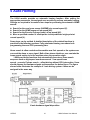
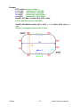
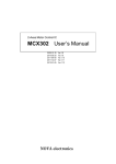
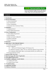
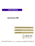
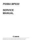
I-8094 provide the functions that automatically executes a home search
sequence such as high-speed near home search → low-speed home
search → encoder Z-phase search → offset driving without CPU intervention. Users
should dispose the hardware signals as the same as the below figure. The figure
shown below illustrates the example of 1-axis driving system. 4 axes can be
assigned in the same way.
X-axis hardware signal disposition
ICPDAS
41
I-8094 Software User Manual
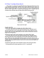
The automatic home search function sequentially executes the steps from step1 to
step 4 that are listed below.
Note: If your hardware signal doesn’t have the near home signal ( the
slow-down signal), you can connect the near home and home signal in the
same pin, and set the
step1 disabled.
Prototype of automatic home search
Note: By inputting a home signal in nIN0 and nIN1, high-speed search is
enabled by using only one home signal.
ICPDAS
42
I-8094 Software User Manual
5.1 Setting the Homing Speed
z void i8094MF_SET_HV(BYTE cardNo, WORD axis, DWORD data)
Description:
This function sets the homing speed.
Parameters:
cardNo:
axis:
data:
Module number
Axis or axes (Please refer to Table 2-1)
Homing speed (in PPS)
Return:
None
EXAMPLE:
i8094MF_ SET_HV(1, AXIS_X, 500);
//set the homing speed of the X axis on module 1 to 500 PPS.
5.2 Using an Limit Switch as the HOME sensor
z void i8094MF_HOME _LIMIT(BYTE cardNo, WORD axis, WORD nType)
Description:
This function sets the Limit Switch to be used as the HOME sensor.
Parameters:
cardNo:
axis:
nType:
Module number
Axis axes (Please refer to Table 2-1)
0: Does not use the LIMIT SWITCH as the HOME sensor;
1: Use the LIMIT SWITCH as the HOME sensor
Return:
None
EXAMPLE:
i8094MF_ HOME_LIMIT(1, AXIS_X, 0);
//Do not use the Limit Switch as the HOME sensor.
ICPDAS
43
I-8094 Software User Manual
5.3 Setting the Homing Mode
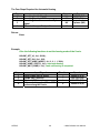
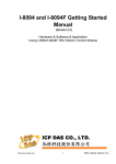
5.3.1 Step 1: High-Speed Near Home Search
Drive pulses are output in the specified direction at the speed that is set in the
drive speed (V) until the near home signal (nIN0) becomes active. To perform
high-speed search operation, set a higher value for the Acceleration/deceleration
driving is performed and when the near home signal (nIN0) becomes active, the
operation stops by decelerating.
Home search for step1
Irregular operation
(1) The near home signal (nIN0) is already active before Step 1 starts.
→ Proceeds with Step 2.
(2) The limit signal in the detection direction is already active before Step 1 starts.
→ Proceeds with Step 2.
(3) The limit signal in the detection direction is activated during execution.
→ Stops driving and proceeds with Step 2.
ICPDAS
44
I-8094 Software User Manual
5.3.2 Step 2: Low-Speed Home Search
Drive pulses are output in the specified direction at the speed that is set as the
home detection speed (HV) until the home signal (nIN1) becomes active. To
perform low-search operation, set a lower value for the home search speed (HV)
than the initial speed (SV). A constant speed-driving mode is applied and the
operation stops instantly when the home signal (nIN1) becomes active.
Home search for step2
Irregular operation
(1) The home signal (nIN1) is already active before Step 2 starts.
→ The motor drives the axis in the direction opposite to the specified search
direction at the home search speed (HV) until the home signal (nIN1) becomes
inactive. When the home signal (nIN1) becomes inactive, the function executes
Step2 from the beginning.
(2) The limit signal in the search direction is active before Step 2 starts.
→ The motor drives the axis in the direction opposite to the specified search
direction at the home search speed (HV) until the home signal (nIN1) becomes
active. When the home signal (nIN1) becomes actives, the motor drivers in the
direction opposite to the specified search direction at the home search speed (HV)
until the home signal (nIN1) becomes inactive, the function executes Step2 from
the beginning.
(3) The limit signal in the search direction becomes active during execution.
→ Driving stops and the same operation as for (2) → is performed.
ICPDAS
45
I-8094 Software User Manual
5.3.3 Step 3: Low-Speed Z-phase Search
Drive pulses are output in the specified direction at the speed that is set as the
home search speed (HV) until the encoder Z-phase signal (nIN2) becomes active.
To perform low-speed search operation, set a lower value for the home search
speed (HV than the initial speed (SV)). A fixed speed-driving mode is applied and
driving stops instantly when the encoder Z-phase signal (nIN2) becomes active. As
the search condition for stopping driving, the AND condition of the encoder
Z-phase signal (nIN2) and the home signal (nIN1) can be applied.
Home search for step3
Note: (1) If the encoder Z-phase signal (nIN2) is already active at the start
of Step 3,
an error occurs. Automatic home search ends. Adjust the mechanical
system so that Step 3 always starts from an inactive state with a
stable encoder Z-phase signal (nIN2).
(2) If the limit signal in the search direction is already active before
the start of Step 3. Automatic home search ends.
(3) If the limit signal in the search direction becomes active during
execution, search operation is interrupted. Automatic home search
ends.
ICPDAS
46
I-8094 Software User Manual
5.3.4 Step 4: High-Speed Offset Drive
The function outputs as many driving pulses as the pulse count (P) that is set,
in the specified direction at the speed that is set in the drive speed (V). Use this
step to move the axis from the mechanical home position to the operation home
position. Through mode setting, the logical position counter and real position
counter can be cleared after moving. If the drive direction limit signal becomes
active before the start or during execution of Step 4, the operation stops due to an
error and 1 is set in the search direction limit error bit (D2 or D3) of the nRR2
register.
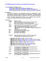
z void i8094MF_SET_HOME_MODE(BYTE cardNo, WORD axis, WORD nStep1,
WORD nStep2, WORD nStep3, WORD nStep4 , long data)
Description:
This function sets the homing method and other related parameters.
Parameters:
cardNo:
axis:
nStep1:
Module number
Axis or axes (Please refer to Table 2-1)
0: Step 1 is not executed
1: Moves in a positive direction
2: Moves in a negative direction
nStep2:
0: Step 2 is not executed
1: Moves in a positive direction
2: Moves in a negative direction
nStep3:
0: Step 3 is not executed
1: Moves in a positive direction
2: Moves in a negative direction
nStep4:
0: Step 4 is not executed
1: Moves in a positive direction
2: Moves in a negative direction
data:
ICPDAS
Offset value (0 ~ 2,147,483,647)
47
I-8094 Software User Manual
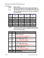
The Four Steps Required for Automatic Homing
Step
1
2
3
4
Action
Searching for the Near Home sensor
Searching for the HOME sensor
Searching for the encoder Z-phase
signal
Moves to the specified position
Speed
V
HV
Sensor
NHOME (IN0)
HOME (IN1)
HV
Z-phase (IN2)
V
Return:
None
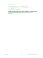
Example:
//Use the following functions to set the homing mode of the X axis.
i8094MF_SET_V(1, 0x1, 20000);
i8094MF_SET_HV(1, 0x1, 500);
i8094MF_SET_HOME_MODE(1, 0x1, 2, 2, 1, 1, 3500);
i8094MF_HOME_START(1, 0x1); //start auto-homing.
i8094MF_WAIT_HOME(1, 0x1); //wait until homing is completed.
Step
1
2
3
4
ICPDAS
Input Signal
Near HOME (IN0) is active
HOME (IN1) is active
Z-phase (IN2) is active
No sensor is required. Move 3500
pulses along the X axis.
48
Direction
+
+
Speed
20000 PPS (V)
500 PPS (HV)
500 PPS (HV)
20000 PPS (V)
I-8094 Software User Manual
5.4 Starting the Homing Sequence
z void i8094MF_HOME _START(BYTE cardNo, WORD axis)
Description:
This function starts the home search of assigned axes.
Parameters:
cardNo:
axis:
Module number
Axis or axes (Please refer to Table 2-1)
Return:
None
Example:
i8094MF_ HOME_START(1, AXIS_X);
//start the automatic homing sequence for the X axis on module 1.
5.5 Waiting for the Homing sequence to be Completed
z BYTE i8094MF _HOME_WAIT(BYTE cardNo, WORD axis)
Description:
This function assigns commands to be performed while waiting for the
automatic home search of all assigned axes to be completed.
Parameters:
cardNo:
axis:
Module number
Axis axes (Please refer to Table 2-1)
Return:
YES
NO
The Homing sequence has been completed.
The Homing sequence is not complete.
Example:
if (i8094MF_HOME_WAIT(1, AXIS_X) == NO)
{
//perform some actions here if the X axis on module 1 has not completed
//its homing sequence.
}
ICPDAS
49
I-8094 Software User Manual
6 General Motion Control
6.1 Independent Axis Motion Control
z
z
z
z
The motion of each axis can be started independently.
Multiple axes are moving at the same time.
Each axis is moving independently.
Each axis can be commanded to change motion, such as changing the number
of pulses or the speed.
z Each axis can be commanded to stop slowly or suddenly to meet the individual
requirements.
z Independent axis motion can work with interpolation or synchrous action to do
more complicated and versatile motion.
6.1.1 Setting the Acceleration/Deceleration Mode
Symmetric T-curve
Asymmetric T-curve
Symmetric S-curve
ICPDAS
50
I-8094 Software User Manual
z void i8094MF_NORMAL_SPEED(BYTE cardNo, WORD axis , WORD nMode)
Description:
The function sets the speed mode.
Parameters:
cardNo:
Module number
axis:
Axis (Please refer to Table 2-1)
nMode:
0 Æ Symmetric T-curve (Please set SV, V, A, and AO)
1 Æ Symmetric S-curve (Please set SV, V, K, and AO)
2 Æ Asymmetric T-curve (Please set SV, V, A, D, and AO)
3 Æ Asymmetric S-curve (Please set SV, V, K, L, and AO)
Return:
None
Example:
BYTE cardNo=1; //select module 1.
i8094MF_SET_MAX_V(cardNo, AXIS_XYZU, 20000);
//set the max. speed of XYZU axes to 20K PPS.
//========================================================
i8094MF_NORMAL_SPEED(cardNo, AXIS_XYZU, 0);
//use a symmetric T-curve for all axes on module 1.
i8094MF_SET_V(cardNo, AXIS_XYZU, 2000);
//set the speed of all axes on module 1 to 2000 PPS.
i8094MF_SET_A(cardNo, AXIS_XYZU,1000);
//set the acceleration of all axes on module 1 to 1000 PPS/Sec.
i8094MF_SET_SV(cardNo, AXIS_XYZU, 2000);
//set the start speed of all axes on module 1 to 2000 PPS.
i8094MF_SET_AO(cardNo, AXIS_XYZU, 9);
//set the number of remaining offset pulses for all axes to 9 pulses.
i8094MF_FIXED_MOVE(cardNo, AXIS_XYZU, 10000);
//move all axes on module 1 for 10000 pulses.
//========================================================
i8094MF_NORMAL_SPEED(cardNo, AXIS_XYZU,1);
//use a symmetric S-curve for all axes on module 1.
i8094MF_SET_V(cardNo, AXIS_XYZU, 2000);
//set the speed of all axes on module 1 to 2000 PPS.
i8094MF_SET_K(cardNo, AXIS_XYZU, 50);
//set the acceleration rate of all axes on module 1 to 500 PPS/Sec^2.
i8094MF_SET_SV(cardNo, AXIS_XYZU, 200);
//set the start speed of all axes on module 1 to 200 PPS.
i8094MF_SET_AO(cardNo, AXIS_XYZU, 9);
//set the number of remaining offset pulses to 9 pulses for all axes.
ICPDAS
51
I-8094 Software User Manual
i8094MF_FIXED_MOVE(cardNo, AXIS_XYZU, -10000);
//move all axes on module 1 for 10000 pulses in reverse direction.
//========================================================
i8094MF_NORMAL_SPEED(cardNo, AXIS_XYZU,2);
//use an asymmetric T-curve for all axes on module 1.
i8094MF_SET_V(cardNo, AXIS_XYZU, 2000);
//set the speed of all axes on module 1 to 2000 PPS.
i8094MF_SET_A(cardNo, AXIS_XYZU,1000 );
//set the acceleration of all axes on module 1 to 1000 PPS/Sec.
i8094MF_SET_D(cardNo, AXIS_XYZU, 500);
//set the deceleration of all axes on module 1 to 500 PPS.
i8094MF_SET_SV(cardNo, AXIS_XYZU, 200);
//set the start speed of all axes on module 1 to 200 PPS.
i8094MF_SET_AO(cardNo, AXIS_XYZU, 9);
//set the number of remaining offset pulses to 9 pulses for all axes.
i8094MF_FIXED_MOVE(cardNo, axis, 10000);
//move all axes on module 1 for 10000 pulses.
//========================================================
i8094MF_NORMAL_SPEED(cardNo, AXIS_XYZU,3);
//use an asymmetric S-curve for all axes on module 1.
i8094MF_SET_V(cardNo, AXIS_XYZU, 2000);
//set the speed of all axes on module 1 to 2000 PPS.
i8094MF_SET_K(cardNo, AXIS_XYZU, 50);
//set the acceleration rate of all axes on module 1 to 500 PPS/Sec^2.
i8094MF_SET_L(cardNo, AXIS_XYZU, 30);
//set the deceleration rate of all axes on module 1 to 300 PPS/Sec^2.
i8094MF_SET_SV(cardNo, AXIS_XYZU, 200);
//set the start speed of all axes on module 1 to 200 PPS.
i8094MF_SET_AO(cardNo, AXIS_XYZU, 9);
//set the number of remaining offset pulses to 9 pulses for all axes.
i8094MF_FIXED_MOVE(cardNo, AXIS_XYZU, 10000);
//move all axes on module 1 for 10000 pulses.
Note:
ICPDAS
Relevant parameters must be set to achieve the desired motion.
52
I-8094 Software User Manual
6.1.2 Setting the Start Speed
z void i8094MF_SET_SV(BYTE cardNo, WORD axis, DWORD data)
Description:
This function sets the start speed for the assigned axes.
Parameters:
cardNo:
axis:
data:
Module number
Axis or axes (Please refer to Table 2-1)
The range is the same as for speed, and must not be zero or
larger than the maximum speed. The maximum value is
4,000,000 PPS. For interpolation, set the speed value for axis1
is enough.
Return:
None
Example:
i8094MF_SET_SV(1, AXIS_X, 1000);
//set the starting speed for the X axis on module 1 to 1000 PPS.
ICPDAS
53
I-8094 Software User Manual
6.1.3 Setting the Desired Speed
z void i8094MF_SET_V(BYTE cardNo, WORD axis, DWORD data)
Description:
This function sets the desired speed for the assigned axes.
Parameters:
cardNo:
axis:
data:
Module number
Axis or axes (Please refer to Table 2-1)
The range is the same as for speed, and must not be zero or
larger than the maximum speed. The maximum value is
4,000,000 PPS. For interpolation, set the speed value for axis1
is enough.
Return:
None
Example:
i8094MF_SET_V(1, AXIS_X, 120000L);
//set the speed for the X axis on module 1 to 120000 PPS.
6.1.4 Setting the Acceleration
z void i8094MF_SET_A(BYTE cardNo, WORD axis, DWORD data)
Description:
This function sets the acceleration value for the assigned axes.
Parameters:
cardNo:
axis:
data:
ICPDAS
Module number
Axis or axes (Please refer to Table 2-1)
The acceleration value. The units are PPS/Sec. This value is
related to the maximum speed value defined by
i8094MF_SET_MAX_V() function. The maximum available
acceleration value is MAX_V * 125. The minimum acceleration
value is MAX_V ÷ 64, and all other acceleration values are
the integral multipliers of this value. The practical value for
application depends on the capability of the motor drive and
motor.
54
I-8094 Software User Manual
Return:
None
Example:
i8094MF_SET_MAX_V(1, AXIS_X, 20000);
//set the maximum speed value of the X axis as 20,000 PPS.
//therefore, do not set any acceleration value that is larger than
//20,000*125 PPS/sec. And 20,000 *125 = 2,500,000.
i8094MF_SET_A(1, AXIS_X, 100000L);
//set the acceleration value of the X axis on module 1 to 100K PPS/Sec.
ICPDAS
55
I-8094 Software User Manual
6.1.5 Setting the Deceleration
z void i8094MF_SET_D(BYTE cardNo, WORD axis, DWORD data)
Description:
This function sets the deceleration value for the assigned axes.
Parameters:
cardNo:
axis:
data:
Module number
Axis or axes (Please refer to Table 2-1)
The deceleration value. The units are PPS/Sec. This value is
related to the maximum speed value defined by
i8094MF_SET_MAX_V() function. The maximum available
deceleration value is MAX_V * 125. The minimum deceleration
value is MAX_V ÷ 64, and all other deceleration values are
the integral multipliers of this value. The practical value for
application depends on the capability of the motor drive and
motor.
Return:
None
Example:
i8094MF_SET_MAX_V(1, AXIS_X, 20000);
//set the maximum speed value of the X axis as 20,000 PPS.
//therefore, do not set any deceleration value that is larger than
//20,000*125 PPS/sec. And 20,000 *125 = 2,500,000.
i8094MF_SET_D(1, AXIS_X, 100000L);
//set the deceleration value of the X axis on module 1 to 100K PPS/Sec.
ICPDAS
56
I-8094 Software User Manual
6.1.6 Setting the Acceleration Rate
z void i8094MF_SET_K(BYTE cardNo, WORD axis, DWORD data)
Description:
The function sets the acceleration rate (i.e., Jerk) value for the assigned axes.
Parameters:
cardNo:
axis:
data:
Module number
Axis or axes (Please refer to Table 2-1)
The acceleration rate (jerk) value. The units are PPS/Sec 2 . This
value is related to the maximum speed value defined by
i8094MF_SET_MAX_V() function. The maximum available
acceleration rate value is MAX_V * 781.25. The minimum
acceleration value is MAX_V * 0.0119211, and all other
acceleration values are the integral multipliers of this value.
The practical value for application depends on the capability
of the motor drive and motor. Note: since the DWORD can not
represent the maximum value; therefore, this value is given by
dividing the desired value by 10.
Return:
None
Example:
i8094MF_SET_MAX_V(1, AXIS_X, 20000);
//set the maximum speed value of the X axis as 20,000 PPS.
//therefore, do not set any jerk value that is larger than
//20,000*781.25 PPS/sec^2. And 20,000 *781.25 = 15,625,000.
i8094MF_SET_K(1, AXIS_X, 1000);
//set the acceleration rate value of the X axis on module 1 to
//1,000*10 (= 10,000) PPS/Sec^2.
ICPDAS
57
I-8094 Software User Manual
6.1.7 Setting the Deceleration Rate
z void i8094MF_SET_L(BYTE cardNo, WORD axis, DWORD data)
Description:
This function sets the deceleration rate (i.e., Jerk) value for the assigned axes.
Parameters:
cardNo:
axis:
data:
Module number
Axis or axes (Please refer to Table 2-1)
The deceleration rate value. The units are PPS/Sec 2 . This
value is related to the maximum speed value defined by
i8094MF_SET_MAX_V() function. The maximum available
deceleration rate value is MAX_V * 781.25. The minimum
deceleration value is MAX_V * 0.0119211, and all other
deceleration values are the integral multipliers of this value.
The practical value for application depends on the capability
of the motor drive and motor. Note: since the DWORD can not
represent the maximum value; therefore, this value is given by
dividing the desired value by 10.
Return:
None
Example:
i8094MF_SET_MAX_V(1, AXIS_X, 20000);
//set the maximum speed value of the X axis as 20,000 PPS.
//therefore, do not set any deceleration rate value that is larger
//than 20,000*781.25 PPS/sec^2. And 20,000 *781.25 = 15,625,000.
i8094MF_SET_L(1, AXIS_X, 1000);
//set the acceleration rate value of the X axis on module 1 to
//1,000*10 (= 10,000) PPS/Sec^2.
ICPDAS
58
I-8094 Software User Manual
6.1.8 Setting the Value of the Remaining Offset Pulses
z void i8094MF_SET_AO(BYTE cardNo, WORD axis, short int data)
Description:
This function sets the number of remaining offset pulses for the assigned axes.
Please refer to the figure below for a definition of the remaining offset pulse value.
Parameters:
cardNo:
axis:
data:
Module number
Axis or axes (Please refer to Table 2-1)
The number of remaining offset pulses. (-32,768 ~ +32,767)
Return:
None
Example:
i8094MF_SET_AO(1, AXIS_X, 200);
//set the number of remaining offset pulses for the X axis on
//module 1 to 200 pulses.
ICPDAS
59
I-8094 Software User Manual
6.1.9 Fixed Pulse Output
z BYTE i8094MF_FIXED_MOVE(BYTE cardNo, WORD axis, long data)
Description:
Command a point-to-point motion for several independent axes.
Parameters:
cardNo:
axis:
data:
Module number
Axis (Please refer to Table 2-1.)
The axis can be either X, Y, Z, or U.
Pulses (-2,147,483,648 ~ +2,147,483,647)
Return:
YES
NO
Some errors happen. Use i8094MF_GET_ERROR_CODE () to
identify the errors.
No error.
Example:
BYTE cardNo=1; //select module 1
i8094MF_SET_MAX_V(cardNo, AXIS_XYZU, 20000);
//set the max. velocity of all axes on module 1 to be 20K PPS
i8094MF_NORMAL_SPEED(cardNo, AXIS_XYZU, 0);
//set the speed profile of all axes on module 1 to be symmetric T-curve
i8094MF_SET_V(cardNo, AXIS_XYZU, 2000);
//set the speed of all axes on module 1 to be 2000 PPS
i8094MF_SET_A(cardNo, AXIS_XYZU,1000);
//set the acceleration value of all axes on module 1 to be 1000 PPS/S
i8094MF_SET_SV(cardNo, AXIS_XYZU, 2000);
//set the start velocity of all axes on module 1 to be 2000 PPS
i8094MF_SET_AO(cardNo, AXIS_XYZU, 9);
//set the remaining offset pulses to be 9 PPS
i8094MF_FIXED_MOVE(cardNo, AXIS_XYZU, 10000);
// move 10000 Pulses for each axis on module 1
ICPDAS
60
I-8094 Software User Manual
6.1.10 Continuous Pulse Output
z BYTE i8094MF_CONTINUE_MOVE(BYTE cardNo, WORD axis, long data)
Description:
This function issues a continuous motion command for several independent
axes.
Parameters:
cardNo:
axis:
data:
Module number
Axis or axes (Please refer to Table 2-1)
The axis can be either X, Y, Z, or U.
The specified speed (positive value for CW motion;
negative value for CCW motion)
Return:
YES
NO
An error has occurred.
Use the i8094MF_GET_ERROR_CODE() function to identify
the errors.
No error.
Example:
BYTE cardNo=1; //select module 1
i8094MF_SET_MAX_V(cardNo, AXIS_XYZU, 20000);
//set the maximum speed of all axes on module 1 to 20K PPS.
i8094MF_NORMAL_SPEED(cardNo, AXIS_XYZU, 0);
//set the speed profile for all axes as a symmetric T-curve.
i8094MF_SET_V(cardNo, AXIS_XYZU, 2000);
//set the speed of all axes on module 1 to 2000 PPS.
i8094MF_SET_A(cardNo, AXIS_XYZU, 1000);
//set the acceleration value of all axes to 1000 PPS/S.
i8094MF_SET_SV(cardNo, AXIS_XYZU, 2000);
//set the start velocity of all axes to 2000 PPS
i8094MF_CONTINUE_MOVE(cardNo, AXIS_XYZU, 1000);
//move all axes on module 1 at a speed of 1000 PPS.
ICPDAS
61
I-8094 Software User Manual
6.2 Interpolation Commands
6.2.1 Assigning the Axes for Interpolation
z void i8094MF_AXIS_ASSIGN(BYTE cardNo, WORD axis1, WORD axis2, WORD
axis3)
Description:
This function assigns the axes to be used for interpolation. Either two or three
axes can be assigned using this function. Interpolation commands will refer to the
assigned axes to construct a working coordinate system. The X axis does not
necessarily have to be the first axis. However, it is easier to use the X axis as the
first axis, the Y axis as the second axis, and the Z axis as the third axis.
Parameters:
cardNo:
axis1:
axis2:
axis3:
Module number
The first axis and It can be either X, Y, Z, or U.
Please refer to Table 2-1 for the axis definition.
The second axis and can be either X, Y, Z, or U.
The third axis and can be either X, Y, Z, or U.
Return:
None
EXAMPLE:
i8094MF_AXIS_ASSIGN(1, AXIS_X, AXIS_Y, 0);
//set the X axis of module 1 as the first axis and the Y axis as the second axis.
ICPDAS
62
I-8094 Software User Manual
6.2.2 Setting the Speed and Acc/Dec Mode for Interpolation
z void i8094MF_VECTOR_SPEED(BYTE cardNo, WORD nMode)
Description:
This function assigns the mode of interpolation. Either two or three axes will
join this interpolation. Each interpolation mode will refer to some assigned axes
that construct a working coordinate system. The assigned axes are defined by
i8094MF_AXIS_ASSIGN() funciton. The X axis does not necessarily have to be the
first axis. However, it is easier to let the X axis as the first axis, the Y axis as the
second axis, and the Z axis as the third axis in applications. Different modes need
different settings. Please refer to the mode definitions.
Parameters:
cardNo:
nMode:
Module number
0 Æ 2-axis linear or circular motion at a constant vector speed
(Set VV and VSV; and VV=VSV)
1 Æ 2-axis linear motion using a symmetric T-curve velocity profile
(set VSV, VV, VA, and VAO)
2 Æ 2-axis linear motion using a symmetric S-curve velocity profile
(set VSV, VV, VK, and VAO)
3 Æ 2-axis linear motion using an asymmetric T-curve velocity
profile (set VSV, VV, VA, VD, and VAO)
4 Æ 2-axis linear motion using an asymmetric S-curve velocity
profile (set VSV, VV, VK, VL, and VAO)
5 Æ 2-axis circular motion using a symmetric T-curve velocity
profile (set VSV, VV, VA, and VAO)
6 Æ 2-axis circular motion using an asymmetric T-curve velocity
profile (set VSV, VV, VA, VD, and VAO)
7 Æ 3-axis linear motion at a constant vector speed
(set VV and VSV; and VV=VSV)
8 Æ 3-axis linear motion at using a symmetric T-curve velocity
profile (set VSV, VV, VA, and VAO)
9 Æ 3-axis linear motion using a symmetric S-curve velocity profile
(set VSV, VV, VK, and VAO)
10 Æ3-axis linear motion using an asymmetric T-curve velocity
profile (set VSV, VV, VA, VD, and VAO)
11 Æ3-axis linear motion using an asymmetric S-curve velocity
profile (set VSV, VV, VK, VL, and VAO)
Return:
None
ICPDAS
63
I-8094 Software User Manual
Example:
BYTE cardNo=1; //select module 1.
i8094MF_SET_MAX_V(cardNo, AXIS_XYZU, 20000);
//set the maximum speed of all axes to 20K PPS.
//===============================================
i8094MF_AXIS_ASSIGN(cardNo, AXIS_X, AXIS_Y, 0);
//set the X axis as the first axis and the Y axis as the second axis.
i8094MF_VECTOR_SPEED(cardNo, 0);
//set module 1 to perform 2-axis linear or circular motion
//at a constant vector speed.
i8094MF_SET_VSV(cardNo, 1000);
//set the starting vector speed to 1000 PPS.
i8094MF_SET_VV(cardNo, 1000);
//set the vector speed to 1000 PPS.
i8094MF_LINE_2D(1, 12000, 10000);
//execute the 2-axis linear interpolation motion.
//===============================================
//enable the deceleration function.
i8094MF_AXIS_ASSIGN(cardNo, AXIS_X, AXIS_Y, 0);
//set the X axis as the first axis and the Y axis as the second axis.
i8094MF_VECTOR_SPEED(cardNo, 1);
//set module 1 to perform 2-axis linear motion using a symmetric
//S-curve velocity profile.
i8094MF_SET_VSV(cardNo, 500);
//set the starting vector speed to 500 PPS.
i8094MF_SET_VV(cardNo, 2000);
//set the vector speed to 2000 PPS.
i8094MF_SET_VA(cardNo, 1000);
//set the vector acceleration to 1000 PPS/Sec.
i8094MF_LINE_2D(cardNo, 20000, 10000);
//execute the 2-axis linear interpolation motion.
//===============================================
i8094MF_AXIS_ASSIGN(cardNo, AXIS_X, AXIS_Y, 0);
//set the X axis as the first axis and the Y axis as the second axis.
i8094MF_VECTOR_SPEED(cardNo, 2);
//2-axis linear motion using a symmetric S-curve velocity profile.
i8094MF_SET_VSV(cardNo, 200);
//set the starting vector speed to 200 PPS.
i8094MF_SET_VV(cardNo, 2000);
//set the vector speed to 2000 PPS.
i8094MF_SET_VK(cardNo, 50);
//set the acceleration rate to 500 PPS/Sec.
i8094MF_SET_VAO(cardNo, 20);
//set the value of remaining offset pulses to 20.
ICPDAS
64
I-8094 Software User Manual
i8094MF_LINE_2D(cardNo, 10000, 10000);
//execute the 2-axis linear interpolation motion.
//===============================================
//enable the deceleration function.
i8094MF_AXIS_ASSIGN(cardNo, AXIS_X, AXIS_Y, 0);
//set the X axis as the first axis and the Y axis as the second axis.
i8094MF_VECTOR_SPEED(cardNo, 3);
//2-axis linear motion using an asymmetric T-curve velocity profile.
i8094MF_SET_VSV(cardNo, 100);
//set the start vector speed to 100 PPS.
i8094MF_SET_VV(cardNo, 2000);
//set the vector speed to 2000 PPS.
i8094MF_SET_VA(cardNo, 1000);
//set the vector acceleration to 1000 PPS/Sec.
i8094MF_SET_VD(cardNo, 500);
//set the vector deceleration to 500 PPS/Sec.
i8094MF_SET_VAO(cardNo, 20);
//set the value of remaining offset pulses to 20.
i8094MF_LINE_2D(cardNo, 10000, 5000);
//execute the 2-axis linear interpolation motion.
//===============================================
long fp1=4000;
long fp2=10000;
int sv=200;
int v=2000;
i8094MF_SET_MAX_V(cardNo, AXIS_XYZU, 8000);
i8094MF_AXIS_ASSIGN(cardNo, AXIS_X, AXIS_Y, 0);
//set the X axis as the first axis and the Y axis as the second axis.
i8094MF_VECTOR_SPEED(cardNo, 4);
//2-axis linear motion using an asymmetric S-curve velocity profile.
i8094MF_SET_VSV(cardNo, sv);
//set the starting velocity to sv PPS.
i8094MF_SET_VV(cardNo, v);
//set the vector speed to v PPS.
i8094MF_SET_VK(cardNo, 50);
//set the acceleration rate to 500 PPS/Sec^2.
i8094MF_SET_VL(cardNo, 30);
//set the deceleration rate to 300 PPS/Sec^2.
i8094MF_SET_VAO(cardNo, 20);
//set the value of remaining offset pulses to 20.
i8094MF_LINE_2D(cardNo, fp1, fp2);
//execute the 2-axis linear motion.
//===============================================
long fp1=11000;
ICPDAS
65
I-8094 Software User Manual
long fp2=9000;
long c1=10000;
long c2=0;
int sv=100;
int v=3000;
int a=5000;
int d=5000;
i8094MF_SET_MAX_V(cardNo, AXIS_XYZU, 8000);
i8094MF_AXIS_ASSIGN(cardNo, AXIS_X, AXIS_Y, 0);
//set the X axis as the first axis and the Y axis as the second axis.
i8094MF_VECTOR_SPEED(cardNo, 5);
//2-axis circular motion using a symmetric T-curve velocity profile
i8094MF_SET_VSV(cardNo, sv);
//set the starting vector speed to sv PPS.
i8094MF_SET_VV(cardNo, v);
//set vector speed to v PPS.
i8094MF_SET_VA(cardNo, a);
//set the vector acceleration to a PPS/Sec.
i8094MF_SET_VAO(cardNo, 0);
//set the value of remaining offset pulses to 0 Pulse.
i8094MF_ARC_CW(cardNo, c1,c2, fp1, fp2);
//execute the 2-axis CW circular motion.
//===============================================
long c1=300;
long c2=0;
int sv=100;
int v=3000;
int a=125;
int d=12;
i8094MF_SET_MAX_V(cardNo, AXIS_XYZU, 8000);
i8094MF_AXIS_ASSIGN(cardNo, AXIS_X, AXIS_Y, 0);
//set the X axis as the first axis and the Y axis as the second axis.
i8094MF_VECTOR_SPEED(cardNo, 6);
//2-axis circular motion using an asymmetric T-curve velocity
//profile.
i8094MF_SET_VSV(cardNo, sv);
//set the starting vector speed to sv PPS.
i8094MF_SET_VV(cardNo, v);
//set vector speed to v PPS.
i8094MF_SET_VA(cardNo, a);
//set acceleration to a PPS/Sec.
i8094MF_SET_VD(cardNo, d);
//set the deceleration to d PPS/Sec.
i8094MF_SET_VAO(cardNo, 0);
//set the value of remaining offset pulses to 0.
i8094MF_CIRCLE_CW(cardNo, c1, c2);
ICPDAS
66
I-8094 Software User Manual
//execute the 2-axis CW circular motion.
//===============================================
i8094MF_AXIS_ASSIGN(cardNo, AXIS_X, AXIS_Y, AXIS_Z);
//set axis1 as the X axis, axis2 as the Y axis, and axis3 as the Z axis.
i8094MF_VECTOR_SPEED(cardNo, 7);
//3-axis linear motion at a constant vector speed (VSV=VV).
i8094MF_SET_VSV(cardNo, 1000);
//set the start speed to 1000 PPS.
i8094MF_SET_VV(cardNo, 1000);
//set the constant speed to 1000 PPS.
i8094MF_LINE_3D(cardNo, 10000, 10000,10000);
//execute the 3-axis linear motion.
//===============================================
i8094MF_AXIS_ASSIGN(cardNo, AXIS_X, AXIS_Y, AXIS_Z);
//set axis1 as the X axis, axis2 as the Y axis, and axis3 as the Z-axis.
i8094MF_VECTOR_SPEED(cardNo, 8);
//3-axis linear motion using a symmetric T-curve velocity profile.
i8094MF_SET_VSV(cardNo, 100);
//set the starting speed to 1000 PPS.
i8094MF_SET_VV(cardNo, 3000);
//set the vector speed to 3000 PPS.
i8094MF_SET_VA(cardNo, 500);
//set the vector acceleration to 500 PPS/Sec.
i8094MF_SET_VAO(cardNo, 20);
//set the value of remaining offset pulses to 20.
i8094MF_LINE_3D(cardNo, 10000, 1000,20000);
//execute the 3-axis linear motion
//===============================================
i8094MF_AXIS_ASSIGN(cardNo, AXIS_X, AXIS_Y, AXIS_Z);
//set the axis1 as the X axis, axis2 as the Y axis, and axis3 as the Z axis.
i8094MF_VECTOR_SPEED(cardNo, 9);
//3-axis linear motion using a symmetric S-curve velocity profile.
i8094MF_SET_VSV(cardNo, 100);
//set the starting speed to 1000 PPS.
i8094MF_SET_VV(cardNo, 3000);
//set the vector speed to 3000 PPS.
i8094MF_SET_VK(cardNo, 50);
//set the vector acceleration rate to 500 PPS/Sec^2.
i8094MF_SET_VAO(cardNo, 20);
//set the value of remaining offset pulses to 20.
i8094MF_LINE_3D(cardNo, 10000, 1000,1000);
//execute the 3-axis linear motion.
//===============================================
ICPDAS
67
I-8094 Software User Manual
i8094MF_AXIS_ASSIGN(cardNo, AXIS_X, AXIS_Y, AXIS_Z);
//set the axis1 as the X axis, axis2 as the Y axis, and axis3 as the Z axis.
i8094MF_VECTOR_SPEED(cardNo, 10);
//set the module 1 to perform 3-axis linear motion
//using an asymmetric T-curve speed profile.
i8094MF_SET_VSV(cardNo, 100);
//set the starting speed to 1000 PPS.
i8094MF_SET_VV(cardNo, 2000);
//set the vector speed as 3000 PPS.
i8094MF_SET_VA(cardNo, 1000);
//set the vector acceleration to 1000 PPS/Sec.
i8094MF_SET_VD(cardNo, 500);
//set the vector deceleration to 500 PPS/Sec.
i8094MF_SET_VAO(cardNo, 20);
//set the value of remaining offset pulses to 20.
i8094MF_LINE_3D(cardNo, 10000, 1000,1000);
//execute the 3-axis linear motion.
//===============================================
long fp1=4000;
long fp2=10000;
long fp3=20000;
int sv=200;
int v=2000;
i8094MF_SET_MAX_V(cardNo, AXIS_XYZU, 8000);
i8094MF_AXIS_ASSIGN(cardNo, AXIS_X, AXIS_Y, AXIS_Z);
//set axis1 as the X axis, axis2 as the Y axis, and axis3 as the Z axis.
i8094MF_VECTOR_SPEED(cardNo, 11);
//3-axis linear motion using an asymmetric S-curve velocity profile.
i8094MF_SET_VSV(cardNo, sv);
//set the starting speed to sv PPS.
i8094MF_SET_VV(cardNo, v);
//set the vector speed to v PPS.
i8094MF_SET_VK(cardNo, 50);
//set the vector acceleration rate to 500 PPS/Sec^2.
i8094MF_SET_VL(cardNo, 30);
//set the vector deceleration rate to 300 PPS/Sec^2.
i8094MF_SET_VAO(cardNo, 20);
//set the value of remaining offset pulses to 20.
i8094MF_LINE_3D(cardNo, fp1, fp2,fp3);
//execute the 3-axis linear motion.
Note:
Relevant parameters should be set before issuing the motion command.
6.2.3 Setting the Vector Starting Speed
z void i8094MF_SET_VSV(BYTE cardNo, DWORD data)
ICPDAS
68
I-8094 Software User Manual
Description:
This function sets the starting speed of the principle axis (axis 1) for the
interpolation motion.
Parameters:
cardNo:
data:
Module number
The vector starting speed value (in PPS)
Return:
None
Example:
i8094MF_SET_VSV(1, 1000);
//set the starting speed of the axis 1 for the interpolation motion
//on module 1 to 1000 PPS.
6.2.4 Setting the Vector Speed
z void i8094MF_SET_VV(BYTE cardNo, DWORD data)
Description:
This function sets the vector speed of the interpolation motion. Users do not
need to assign any axes on this function. The speed setting will take effect on the
current working coordinate system which is defined by the
i8094MF_AXIS_ASSIGN() function.
Parameters:
cardNo:
data:
Module number
The vector speed value (in PPS)
Return:
None
Example:
i8094MF_SET_VV(1, 120000L);
//set the vector speed of the interpolation on module 1
//to 120000 PPS.
6.2.5 Setting the Vector Acceleration
z void i8094MF_SET_VA(BYTE cardNo, DWORD data)
ICPDAS
69
I-8094 Software User Manual
Description:
This function sets the vector acceleration for interpolation motion. Users do
not have to assign any axes on this funciton. This speed setting will take effect on
the current working coordinate system which is defined by the
i8094MF_AXIS_ASSIGN() function.
Parameters:
cardNo:
data:
Module number
The vector acceleration value (in PPS/Sec). The units are
PPS/Sec. This value is related to the maximum speed value
defined by i8094MF_SET_MAX_V() function. The maximum
available acceleration value is MAX_V * 125. The minimum
acceleration value is MAX_V ÷ 64, and all other acceleration
values are the integral multipliers of this value. The practical
value for application depends on the capability of the motor
drive and motor.
Return:
None
Example:
i8094MF_SET_MAX_V(1, AXIS_X, 20000);
//set the maximum speed value of the X axis as 20,000 PPS.
//therefore, do not set any acceleration value that is larger than
//20,000*125 PPS/sec. And 20,000 *125 = 2,500,000.
i8094MF_SET_VA(1, 100000L);
//set the vector acceleration of the interpolation motion
//on module 1 to 100K PPS/Sec.
6.2.6 Setting the Vector Deceleration Value
z void i8094MF_SET_VD(BYTE cardNo, DWORD data)
Description:
ICPDAS
70
I-8094 Software User Manual
This function sets the deceleration value for the interpolation motion.
Parameters:
cardNo:
data:
Module number
The vector deceleration value (in PPS/Sec). This value is
related to the maximum speed value defined by
i8094MF_SET_MAX_V() function. The maximum available
deceleration value is MAX_V * 125. The minimum deceleration
value is MAX_V ÷ 64, and all other deceleration values are
the integral multipliers of this value. The practical value for
application depends on the capability of the motor drive and
motor.
Return:
None
Example:
i8094MF_SET_MAX_V(1, AXIS_X, 20000);
//set the maximum speed value of the X axis as 20,000 PPS.
//therefore, do not set any deceleration value that is larger than
//20,000*125 PPS/sec. And 20,000 *125 = 2,500,000.
i8094MF_SET_VD(1, 100000L);
//set the vector deceleration value of interpolation motion
//on module 1 to 100K PPS/Sec.
6.2.7 Setting the Vector Acceleration Rate
z void i8094MF_SET_VK(BYTE cardNo, DWORD data)
Description:
Set the acceleration rate (jerk) value for interpolation motion.
ICPDAS
71
I-8094 Software User Manual
Parameters:
cardNo:
data:
Module number
The acceleration rate (jerk) value. The units are PPS/Sec 2 . This
value is related to the maximum speed value defined by
i8094MF_SET_MAX_V() function. The maximum available
acceleration rate value is MAX_V * 781.25. The minimum
acceleration value is MAX_V * 0.0119211, and all other
acceleration values are the integral multipliers of this value.
The practical value for application depends on the capability
of the motor drive and motor. Note: since the DWORD can not
represent the maximum value; therefore, this value is given by
dividing the desired value by 10.
Return:
None
Example:
i8094MF_SET_MAX_V(1, AXIS_X, 20000);
//set the maximum speed value of the X axis as 20,000 PPS.
//therefore, do not set any jerk value that is larger than
//20,000*781.25 PPS/sec^2. And 20,000 *781.25 = 15,625,000.
i8094MF_SET_VK(1, 10000);
//set the acceleration rate of the interpolation motion on module
// 1 to 10,000 PPS/ Sec^2.
6.2.8 Setting the Vector Deceleration Rate
z void i8094MF_SET_VL(BYTE cardNo, DWORD data)
Description:
This function sets the deceleration rate of the interpolation motion.
ICPDAS
72
I-8094 Software User Manual
Parameters:
cardNo:
data:
Module number
The deceleration rate (Jerk) value. The units are PPS/Sec 2 .
This value is related to the maximum speed value defined by
i8094MF_SET_MAX_V() function. The maximum available
deceleration rate value is MAX_V * 781.25. The minimum
deceleration value is MAX_V * 0.0119211, and all other
deceleration values are the integral multipliers of this value.
The practical value for application depends on the capability
of the motor drive and motor. Note: since the DWORD can not
represent the maximum value; therefore, this value is given by
dividing the desired value by 10.
Return:
None
Example:
i8094MF_SET_MAX_V(1, AXIS_X, 20000);
//set the maximum speed value of the X axis as 20,000 PPS.
//therefore, do not set any deceleration rate value that is larger
//than 20,000*781.25 PPS/sec^2. And 20,000 *781.25 = 15,625,000.
i8094MF_SET_VL(1, 10000);
//set the deceleration rate of the interpolation on module 1 to 10,000 PPS/Sec^2.
6.2.9 Setting the Number of the Remaining Offset Pulses
z void i8094MF_SET_VAO(BYTE cardNo, short int data)
Description:
Setting this value will cause the motion control chip to start deceleration
earlier. The remaining offset pulses will be completed at low speed to allow the
controller to stop immediately when the offset pulse value has been reached.
ICPDAS
73
I-8094 Software User Manual
Please refer to the figure below for more information.
Parameters:
cardNo:
data:
Module number
The number of remaining offset pulses (-32,768 ~ +32,767)
Return:
None
Example:
i8094MF_SET_VAO(1, 200);
//set the number of remaining offset pulse value on module 1 to 200.
6.2.10 2-Axis Linear Interpolation Motion
z BYTE i8094MF_LINE_2D(BYTE cardNo, long fp1, long fp2)
Description:
This function executes a 2-axis linear interpolation motion.
Parameters:
ICPDAS
74
I-8094 Software User Manual
cardNo:
fp1:
fp2:
Module number
The displacement of the axis 1 in Pulses
(-2,147,483,648 ~ +2,147,483,647)
The displacement of the axis 2 in Pulses
(-2,147,483,648 ~ +2,147,483,647)
Return:
YES
NO
An error has occurred.
Use the i8094MF_GET_ERROR_CODE() function to identify
the error.
No errors.
Example:
i8094MF_LINE_2D(1, 12000, 10000);
//execute the 2-axis linear interpolation motion on module 1.
2-axis linear interpolation motion
6.2.11 3-axis Linear Interpolation Motion
z BYTE i8094MF_LINE_3D(BYTE cardNo, long fp1, long fp2, long fp3)
Description:
This function executes a 3-axis linear interpolation motion.
Parameters:
ICPDAS
75
I-8094 Software User Manual
cardNo:
fp1:
fp2:
fp3:
Module number
The displacement of the first axis (axis 1) in Pulses
(-2,147,483,648 ~ +2,147,483,647)
The displacement of the second axis (axis 2) in Pulses
(-2,147,483,648 ~ +2,147,483,647)
The displacement of the third axis (axis 3) in Pulses
(-2,147,483,648 ~ +2,147,483,647)
Return:
YES
NO
An error has occurred.
Use the i8094MF_GET_ERROR_CODE() function to identify
the error.
No errors.
Example:
i8094MF_LINE_3D(1, 10000, 10000, 10000);
//execute the 3-axis linear interpolation motion on module 1.
3-axis linear interpolation motion
6.2.12 2-Axis Circular Interpolation Motion (an Arc)
z BYTE i8094MF_ARC_CW(BYTE cardNo, long cp1, long cp2, long fp1, long fp2)
Description:
This function executes a 2-axis circular interpolation motion in a clockwise
(CW) direction.
ICPDAS
76
I-8094 Software User Manual
Parameters:
cardNo:
cp1:
cp2:
fp1:
fp2:
Module number
The relative position of the center to the current position of
axis 1 in pulses. (-2,147,483,648 ~ +2,147,483,647)
The relative position of the center to the current position of
axis 2 in pulses. (-2,147,483,648 ~ +2,147,483,647)
The displacement of the axis 1 in pulses.
(-2,147,483,648 ~ +2,147,483,647)
Displacement of the axis 2 in pulses.
(-2,147,483,648 ~ +2,147,483,647)
Return:
YES
NO
An error has occurred.
Use the i8094MF_GET_ERROR_CODE () function to identify
the error.
No errors.
Example:
i8094MF_ARC_CW(1, -5000, -5000, -10000, -10000);
//Issues a command to perform a circular motion (an arc)
//in a CW direction. Please refer to the following figure.
2-axis circular motion in a CW direction
z BYTE i8094MF_ARC_CCW(BYTE cardNo, long cp1, long cp2, long fp1, long fp2)
Description:
This function execute a 2-axis circular interpolation motion in a
counter-clockwise (CCW) direction.
Parameters:
cardNo:
ICPDAS
Module number
77
I-8094 Software User Manual
cp1:
cp2:
fp1:
fp2:
The relative position of the center to the current position of
axis 1 in pulses. (-2,147,483,648 ~ +2,147,483,647)
The relative position of the center to the current position of
axis 2 in pulses. (-2,147,483,648 ~ +2,147,483,647)
The displacement of the axis 1 in pulses.
(-2,147,483,648 ~ +2,147,483,647)
Displacement of the axis 2 in pulses.
(-2,147,483,648 ~ +2,147,483,647)
Return:
YES
NO
An error has occurred.
Use the i8094MF_GET_ERROR_CODE() function to identify
the errors.
No errors.
Example:
i8094MF_ARC_CCW(1, -5000, -5000, -10000, -10000);
//Issues a command to perform a circular motion (an arc)
//in a CCW direction. Refer to the following figure.
2-axis circular motion in a CCW direction
6.2.13 2-Axis Circular Interpolation Motion (a Complete Circle)
z BYTE i8094MF_CIRCLE_CW(BYTE cardNo, long cp1, long cp2)
Description:
This function executes a 2-axis circular interpolation motion in a clockwise
(CW) direction.
ICPDAS
78
I-8094 Software User Manual
Parameters:
cardNo:
cp1:
cp2:
Module number
The relative position of the center to the current position of
axis 1 in pulses. (-2,147,483,648 ~ +2,147,483,647)
The relative position of the center to the current position of
axis 2 in pulses. (-2,147,483,648 ~ +2,147,483,647)
Return:
YES
NO
An error has occurred.
Use the i8094MF_GET_ERROR_CODE() function to identify
the errors.
No errors.
Example:
i8094MF_CIRCLE_CW(1, 0, 10000);
//execute a circular motion (a complete circle) in a CW direction on module 1.
z BYTE i8094MF_CIRCLE_CCW(BYTE cardNo, long cp1, long cp2)
Description:
This function executes a 2-axis circular interpolation motion in a
counter-clockwise (CCW) direction.
Parameters:
cardNo:
cp1:
cp2:
Module number
The relative position of the center to the current position of
axis 1 in pulses. (-2,147,483,648 ~ +2,147,483,647)
The relative position of the center to the current position of
axis 2 in pulses. (-2,147,483,648 ~ +2,147,483,647)
Return:
YES
NO
An error has occurred.
Use the i8094MF_GET_ERROR_CODE () function to identify
the error.
No errors
Example:
i8094MF_CIRCLE_CCW(1, 0, 10000);
ICPDAS
79
I-8094 Software User Manual
//execute a circular motion (a circle) in CCW direction
//on module 1
6.3 Synchronous Actions
6.3.1 Setting the Synchronous Action
z void i8094MF_SYNC_ACTION(BYTE cardNo, WORD axis1, WORD axis2,
WORD nSYNC, WORD nDRV, WORD nLATCH, WORD nPRESET)
Description:
This function sets the activation factors (provocatives) and the specified
ICPDAS
80
I-8094 Software User Manual
action when a specified activation factor occurs.
Parameters:
cardNo:
axis1:
axis2:
Module number
This is the monitored axis. It will be checked by hardware.
The axis can be either X, Y, Z, or U. (Please refer to Table 2-1.)
This defined the other axes (or axis) that will take action when
one of the activation factors occurs. The axes are defined in
the following table.
axis1
X
Y
Z
U
none
Y
Z
YZ
U
YU
ZU
YZU
none
Z
U
ZU
X
ZX
UX
ZUX
none
U
X
UX
Y
UY
XY
UXY
none
X
Y
XY
Z
XZ
YZ
XYZ
axis2
0
1
2
3
4
5
6
7
nSYNC:
It defines the activation factors. Multiple activation factors
can be defined at the same time. Available active factors are
listed in the following table.
Value Event
0x0000
0x0001
P ≥ C+
0x0002
P<C+
0x0004
P<C-
0x0008
P ≥ C-
0x0010 D-STA
0x0020 D-END
ICPDAS
Explanation
Disable the synchronous action
The logical/real position counter value exceeded the
COMP+ register value.
Use the i8094MF_SET_COMPARE() function for
selection of a logical/real position.
The logical/real position counter value became less
than the COMP+ register value.
Use the i8094MF_SET_COMPARE() function for
selection of a logical/real position.
The logical/real position counter value became less
than the COMP- register value.
Use the i8094MF_SET_COMPARE() function for
selection of a logical/real position.
The logical/real position counter value exceeded
the COMP- register value.
Use the i8094MF_SET_COMPARE() function for
selection of a logical/real position.
Driving started.
Driving terminated.
81
I-8094 Software User Manual
0x0040 IN3 ↑
0x0080 IN3 ↓
The nIN3 signal rose from the Low to the High level.
The nIN3 signal fell from the High to the Low level.
For example, if the factors P ≥ C+ and IN3 ↑ are set, the nSYNC value is 0x0041
(0x0001 + 0x0040 = 0x0041).
nDRV:
It defines the actions that are related with axial driving.
Available actions are listed in the following table. Only one
driving action can be chosen.
Value Symbol
0
1
FDRV+
2
FDRV-
3
CDRV+
4
CDRV-
5
6
SSTOP
ISTOP
nLATCH:
Explanation
Disable driving action.
Activates fixed pulse driving in the + direction. It
must set the nPRESET value to be “OPSET” which
indicates that i8094MF_SET_PRESET() function will
set the offset value for this FDRV. Therefore, the
companion function, i8094MF_SET_PRESET(), is
necessary. However, this command does not take
effect if the assigned axes, axis2, are moving.
Activates fixed pulse driving in the - direction. It
must set the nPRESET value to be “OPSET” which
indicates that i8094MF_SET_PRESET() function will
set the offset value for this FDRV. Therefore, the
companion function, i8094MF_SET_PRESET(), is
necessary. However, this command does not take
effect if the assigned axes, axis2, are moving.
Activates continuous pulse driving in the +
direction. However, this command does not take
effect if the assigned axes, axis2, are moving.
Activates continuous pulse driving in the - direction.
However, this command does not take effect if the
assigned axes, axis2, are moving.
Stop driving in deceleration.
Stop driving immediately.
It defines the actions that is related of latching position. Available
actions are listed in the following table. Only one of these
actions can be chosen.
Value Symbol
0
ICPDAS
1
LPSAV
2
EPSAV
Explanation
Disable position latch function.
Saves the current logical position counter value (LP)
in the synchronous buffer register (BR).
[LP → LATCH]
Saves the current real position counter value (EP) in
82
I-8094 Software User Manual
the synchronous buffer register (BR).
[EP → LATCH]
After the event is occoured, the i8094MF_GET_LATCH() function can be use to
get the latched value.
nPRESET:
It defines the actions that is related of latching position. Available
actions are listed in the following table. Only one of these
actions can be chosen.
Value Symbol
0
1
LPSET
2
EPSET
3
OPSET
4
VLSET
Explanation
Disable setting function.
Indicates that a new value for the logical position
(LP) will be set. The new value will be set by
i8094MF_SET_PRESET() function.
[LP ← PRESET]
Indicates that a new value for the real position (EP)
will be set. The new value will be set by
i8094MF_SET_PRESET() function.
[EP ← PRESET]
Indicates that a new offset value (P) for the fixed
pulse driving will be set. The new value will be set by
i8094MF_SET_PRESET() function.
[P ← PRESET]
Indicates that a new speed value (V) will be set. The
new value will be set by i8094MF_SET_PRESET()
function.
[V ← PRESET]
Return:
None
Example:
//Ex1. When the rising edge event of IN3 signal of U-axis occurred,
// the real position (EP) is latched and the driving speed of U-axis is changed, too.
i8094MF_SYNC_ACTION(cardNo, AXIS_U, 0, 0X0040, 0, 2, 4);
i8094MF_SET_MAX_V(cardNo, AXIS_U, 5000);
//Set the maximum speed of U-axis to 5K PPS.
i8094MF_NORMAL_SPEED(cardNo, AXIS_U, 0);
//Set the Acc/Dec mode to be symmetric T-curve.
i8094MF_SET_V(cardNo, AXIS_U, 2000);
//Set the speed of U-axis to 2000 PPS.
i8094MF_SET_A(cardNo, AXIS_U, 100000);
//Set the acceleration of U-axis to 100K PPS/S.
i8094MF_SET_SV(cardNo, AXIS_U, 100);
ICPDAS
83
I-8094 Software User Manual
//Set the start speed of U-axis to 100 PPS.
i8094MF_FIXED_MOVE(cardNo, AXIS_U, 10000);
//Set the fixed pulse moving command to 10000 Pulses.
i8094MF_SET_PRESET(cardNo, AXIS_U, 100);
//Set the new speed of U-axis after even activation to 100 PPS.
while (i8094MF_STOP_WAIT(cardNo, AXIS_U) == NO)
{
//If the U-axis of the assigned card is not stop, keep looping
DoEvents();
Sleep(1); //Release the control for a moment
};
//After the event occurred, following line can get latched position.
long Vsb = i8094MF_GET_LATCH(cardNo, AXIS_U);
//Ex2. When the EP value of U-axis exceeds COMP+ (5,000),
//controller will move the Y-axis by 2,000 PPS.
i8094MF_SYNC_ACTION(cardNo, AXIS_U, 2, 0X0001, 1, 0, 3);
i8094MF_SET_COMPARE(cardNo, AXIS_U, 0, 1, 5000);
//Set the COMP+ of U-axis 5,000 and te compared source is real position (EP).
i8094MF_SET_MAX_V(cardNo, AXIS_YU, 9000);
//Set the maximum speed of axesY and U to 9K PPS.
i8094MF_NORMAL_SPEED(cardNo, AXIS_YU, 0);
//Set the Acc/Dec mode to be symmetric T-curve.
i8094MF_SET_V(cardNo, AXIS_YU, 3000);
//Set the speed of axes Y and U to 3,000 PPS.
i8094MF_SET_A(cardNo, AXIS_YU, 200000);
//Set the acceleration of axes Y and U to 200K PPS/S.
i8094MF_SET_SV(cardNo, AXIS_YU, 200);
//Set the start speed of axes Y and U to 200 PPS.
i8094MF_SET_PRESET(cardNo, AXIS_Y, 2000);
//Set the fixed pulse drive of Y-axis to be 2,000 PPS when the activating
//event occurs.
i8094MF_FIXED_MOVE(cardNo, AXIS_U, 10000);
//Command the U-axis to move 10,000 Pulses and the synchronous action
//will happen after a while.
6.3.2 Setting the COMPARE value
z void i8094MF_SET_COMPARE(BYTE cardNo, WORD axis, WORD nSELECT,
WORD nTYPE, long data)
Description:
This function sets the values of COMPARE registers. Howerer, it will disable
the functions of software limits.
Parameters:
cardNo:
ICPDAS
Module number
84
I-8094 Software User Manual
axis:
Axis or axes (Please refer to Table 2-1)
nSELECT:
Select the COMPARE register
0 Æ COMP+
1 Æ COPMSelect the souece for comparison
0 Æ Position(P) = LP
1 Æ Position(P) = EP
Set the COMPARE value: -2,147,483,648 ~ +2,147,483,647
nTYPE:
data:
Return:
None
Example:
i8094MF_SET_COMPARE(cardNo, AXIS_U, 0, 1, 5000);
//Set the comparison function for U-Axis.
//Set the compared source to be EP; and the COMP+ value to 5000.
ICPDAS
85
I-8094 Software User Manual
6.3.3 Get the LATCH value
z long i8094MF_GET_LATCH(BYTE cardNo, WORD axis)
Description:
This function gets the values from the LATCH register.
Parameters:
cardNo:
axis:
Module number
The axis can be either X, Y, Z, or U. Please refer to Table 2-1.
Return:
Value of the LATCH register: -2,147,483,648 ~ +2,147,483,647
Example:
long data = i8094MF_GET_LATCH(1, AXIS_Y);
//Get the latched value which is from Y-axis of card 1.
6.3.4 Set the PRESET data for synchronous action
z void i8094MF_SET_PRESET(BYTE cardNo, WORD axis, long data)
Description:
This function sets the PRESET value for synchronous action.
Parameters:
cardNo:
Module number
axis:
The axis can be either X, Y, Z, or U. Please refer to Table 2-1.
data:
LP: -2,147,483,648 ~ +2,147,483,647
EP: -2,147,483,648 ~ +2,147,483,647
P : -2,147,483,648 ~ +2,147,483,647
V : Please refer to section 2.5.
Return:
None
Example:
Please refer to the examples in section 6.3.1.
ICPDAS
86
I-8094 Software User Manual
6.4 Continuous Interpolation
Some continuous interpolation will (that need CPU resource)block the
programe. When you use those API in real time thread, you must take care that.
If it is broken and stopped,please solve it refer in section 6.5.5 !
6.4.1 2-Axis Rectangular Motion
z BYTE i8094MF_RECTANGLE(
BYTE cardNo, WORD axis1, WORD axis2,
WORD nAcc, WORD Sp, WORD nDir, long Lp, long Wp, long Rp,
DWORD RSV,DWORD RV, DWORD RA, DWORD RD)
Description:
Continuous interpolation will be performed to create a rectangular motion,
which is formed by 4 lines and 4 arcs. The length of each side can be changed. The
radius of each arc is the same and it can also be changed. The deceleration point
will be calculated automatically. This is a command macro command that appears
in various motion applications. However, it is a software macro-function; therefore,
it requires CPU resource to run this function.
Parameters:
cardNo:
axis1:
axs2:
nAcc:
Sp:
nDir:
Lp:
Wp:
Rp:
RSV:
RV:
RA:
RD:
Module number
The first axis (axis 1). Please refer to Table 2-1.
The first axis and It can be either X, Y, Z, or U.
The second (axis 2). Please refer to Table 2-1.
The first axis and It can be either X, Y, Z, or U.
0 Æ constant vector speed interpolation mode
1 Æ symmetric T-curve Acc/Dec interpolation mode
Start point 0 ~ 7. (Sp0 ~ Sp7 are defined in the following
figure)
Direction of movement
0: CCW; 1: CW
Length in Pulses (1 ~ 2,147,483,647)
Width in Pulses (1 ~ 2,147,483,647)
Radius of each in pulses (1 ~ 2,147,483,647)
Starting speed (in PPS)
Vector speed (in PPS)
Acceleration (PPS/Sec)
Deceleration of the last segment (in PPS/Sec)
Return:
YES
NO
ICPDAS
An error has occurred.
Use the i8094MF_GET_ERROR_CODE() function to identify
the error.
No errors.
87
I-8094 Software User Manual
Example:
BYTE cardNo=1; //select module 1.
int sv=1000;
//starting speed: 1000 PPS.
int v=10000;
//vector speed: 10000 PPS.
int a=5000;
//acceleration: 5000 PPS/Sec.
int d=5000;
//deceleration: 5000 PPS/Sec.
i8094MF_SET_MAX_V(cardNo, AXIS_XYZU, 16000);
//set the maximum speed to 16000 PPS.
i8094MF_RECTANGLE(cardNo, AXIS_X, AXIS_Y, 1, 0, 0, 20000, 10000, 1000, sv, v,
a, d);
//execute a rectangular motion on the XY plane
ICPDAS
88
I-8094 Software User Manual
6.4.2 2-Axis Continuous Linear Interpolation
z BYTE i8094MF_LINE_2D_INITIAL(BYTE cardNo, WORD axis1, WORD axis2,
DWORD VSV,DWORD VV, DWORD VA)
Description:
This function sets the necessary parameters for a 2-axis continuous linear
interpolation using symmetric T-curve speed profile.
Parameters:
cardNo:
axis1:
axis2:
VSV:
VV:
VA:
Module number
The first axis (axis 1). Please refer to Table 2-1.
The first axis and It can be either X, Y, Z, or U.
The second axis (axis 2). Please refer to Table 2-1.
The second axis and It can be either X, Y, Z, or U.
Starting speed (in PPS)
Vector speed (in PPS)
Vector acceleration (PPS/Sec)
Return:
None
Example:
i8094MF_LINE_2D_INITIAL(…);
//This function should be defined before the i8094MF_LINE_2D_CONTINUE()
//function is used. Please refer to the example of this function.
z BYTE i8094MF_LINE_2D_CONTINUE(BYTE cardNo, WORD nType, long fp1,
long fp2)
Description:
This function executes a 2-axis continuous linear interpolation. However, it is
a software macro-function; therefore, it requires CPU resource to run this
function.
Parameters:
cardNo:
nType:
fp1:
fp2:
Module number
0: 2-axis linear continuous interpolation
1: end of 2-axis linear continuous interpolation
The assigned number of pulses for the axis 1 (in Pulses)
(-2,147,483,648 ~ +2,147,483,647)
The assigned number of pulses for the axis 2 (in Pulses)
(-2,147,483,648 ~ +2,147,483,647)
Return:
YES
ICPDAS
An error has occurred.
89
I-8094 Software User Manual
NO
Use the i8094MF_GET_ERROR_CODE () function to identify
the error.
No errors.
Example:
BYTE cardNo=1;
//select module 1.
int sv=300;
//starting speed: 300 PPS.
int v=18000;
//vector speed: 18000 PPS.
long a=500000L; //acceleration: 500000 PPS/Sec.
int loop1;
i8094MF_SET_MAX_V(cardNo, AXIS_XYZU,160000L);
i8094MF_LINE_2D_INITIAL(cardNo, AXIS_X, AXIS_Y, sv, v, a);
for (loop1=0; loop1<10000; loop1++)
{
i8094MF_LINE_2D_CONTINUE(cardNo, 0, 100, 100);
i8094MF_LINE_2D_CONTINUE(cardNo, 0, -100, -100);
}
i8094MF_LINE_2D_CONTINUE(cardNo, 1, 100, 100);
ICPDAS
90
I-8094 Software User Manual
6.4.3 3-Axis Continuous Linear Interpolation
z BYTE i8094MF_LINE_3D_INITIAL(BYTE cardNo, WORD axis1, WORD axis2,
WORD axis3, DWORD VSV, DWORD VV, DWORD VA)
Description:
This function sets the necessary parameters for a 3-axis continuous linear
interpolation using symmetric T-curve speed profile.
Parameters:
cardNo:
axis1:
axis2:
axis3:
VSV:
VV:
VA:
Module number
The first axis (axis 1). Please refer to Table 2-1.
The first axis and It can be either X, Y, Z, or U.
The second axis (axis 2). Please refer to Table 2-1.
The second axis and It can be either X, Y, Z, or U.
The third axis (axis 3). Please refer to Table 2-1.
The third axis and It can be either X, Y, Z, or U.
Starting speed (in PPS)
Vector speed (in PPS)
Vector acceleration (PPS/Sec)
Return:
None
Example:
i8094MF_LINE_3D_INITIAL(…);
//This function should be defined before the i8094MF_LINE_3D_CONTINUE()
//function is used. Please refer to the example of this function.
ICPDAS
91
I-8094 Software User Manual
z BYTE i8094MF_LINE_3D_CONTINUE(BYTE cardNo, WORD nType, long fp1,
long fp2, long fp3)
Description:
This function execute a 3-axis continuous linear interpolation. However, it is a
software macro-function; therefore, it requires CPU resource to run this
function.
Parameters:
cardNo:
nType:
fp1:
fp2:
fp3:
Module number
0: 3-axis linear continuous interpolation
1: end of 2-axis linear continuous interpolation
The assigned number of pulses for axis 1
(-2,147,483,648 ~ +2,147,483,647)
The assigned number of pulses for axis 2
(-2,147,483,648 ~ +2,147,483,647)
The assigned number of pulses for axis 3
(-2,147,483,648 ~ +2,147,483,647)
Return:
YES
NO
An error has occurred.
Use the i8094MF_GET_ERROR_CODE ()
function to identify the error.
No errors.
Example:
BYTE cardNo=1; //select module 1.
int sv=300;
//starting speed: 300 PPS
int v=18000;
//vector speed: 18000 PPS
long a=500000L; //acceleration: 500000 PPS/Sec
int loop1;
i8094MF_SET_MAX_V(cardNo, AXIS_XYZU,160000L);
i8094MF_LINE_3D_INITIAL(cardNo, AXIS_X, AXIS_Y, sv, v, a);
for (loop1=0; loop1<10000; loop1++)
{
i8094MF_LINE_3D_CONTINUE(cardNo, 0, 100, 100, 100);
i8094MF_LINE_3D_CONTINUE(cardNo, 0, -100, -100, -100);
}
i8094MF_LINE_3D_CONTINUE(cardNo, 1, 100, 100, 100);
ICPDAS
92
I-8094 Software User Manual
6.4.4 Mixed Linear and Circular 2-axis motions in Continuous
Interpolation
z void i8094MF_MIX_2D_INITIAL(BYTE cardNo, WORD axis1, WORD axis2,
WORD nAcc, DWORD VSV , DWORD VV , DWORD VA)
Description:
This function does the initial settings for mixed linear and circular 2-axis
motions in continuous interpolation.
Parameters:
cardNo:
axis1:
axis2:
nAcc:
VSV:
VV:
VA:
Module number
The first axis (axis 1). Please refer to Table 2-1.
The first axis and It can be either X, Y, Z, or U.
The second axis (axis 2). Please refer to Table 2-1.
0 Æ constant speed (VV)
1 Æ symmetric T-curve Acc/Dec (VSV、VV、VA)
Starting speed (in PPS)
Vector speed (in PPS)
Vector acceleration (PPS/Sec)
Return:
None
Example:
i8094MF_MIX_2D_INITIAL(…);
//This function should be defined before the i8094MF_MIX_2D_CONTINUE()
//function is used. Please refer to the example of this function.
ICPDAS
93
I-8094 Software User Manual
z BYTE i8094MF_MIX_2D_CONTINUE(BYTE cardNo, WORD nAcc,
WORD nType, long cp1, long cp2, long fp1, long fp2)
Description:
This function executes mixed linear and circular 2-axis motion in continuous
interpolation. However, it is a software macro-function; therefore, it requires
CPU resource to run this function.
Parameters:
cardNo:
nAcc:
Module number
0 Æ continuous interpolation.
1 Æ it is the last command of this continuous interpolation. In
Acc/Dec mode, it will perform a deceleration stop. In
constant speed mode, it will directly stop rather than
decelerate.
nType:
1 Æi8094MF_LINE_2D(BYTE cardNo, long fp1, long fp2);
2 Æi8094MF_ARC_CW(BYTE cardNo, long cp1, long cp2, long fp1, long fp2);
3 Æi8094MF_ARC_CCW(BYTE cardNo, long cp1, long cp2, long fp1, long fp2);
4 Æi8094MF_CIRCLE_CW(BYTE cardNo, long cp1, long cp2);
5 Æi8094MF_CIRCLE_CCW(BYTE cardNo, long cp1, long cp2);
cp1:
cp2:
fp1:
fp2:
fp1:
It assigns the center point data at axis 1.
(-2,147,483,648 ~ +2,147,483,647)
It assigns the center point data at axis 2.
(-2,147,483,648 ~ +2,147,483,647)
It assigns the end point data at axis 1.
(-2,147,483,648 ~ +2,147,483,647)
It assigns the end point data at axis 2.
(-2,147,483,648 ~ +2,147,483,647)
The assigned number of pulses for axis 1
(-2,147,483,648 ~ +2,147,483,647)
Return:
YES
NO
ICPDAS
An error has occurred. Use the
i8094MF_GET_ERROR_CODE () function to identify the error.
No errors.
94
I-8094 Software User Manual
Example:
BYTE cardNo=1;
int sv=300;
int v=18000;
long a=500000L;
//select module 1.
//starting speed: 300 PPS
//vector speed: 18000 PPS
//acceleration: 500000 PPS/Sec
unsigned short loop1;
i8094MF_SET_MAX_V(cardNo, AXIS_XYZU, 160000L);
i8094MF_MIX_2D_INITIAL(cardNo, AXIS_X, AXIS_Y, 1, sv, v, a);
for (loop1 = 0; loop1 < 10000; loop1++)
{
i8094MF_MIX_2D_CONTINUE (cardNo, 0, 1, 0, 0, 100, 100);
i8094MF_MIX_2D_CONTINUE (cardNo, 0, 2, 100, 0, 100, 100);
}
i8094MF_MIX_2D_CONTINUE (cardNo, 1, 4, 100, 100, 0, 0);
ICPDAS
95
I-8094 Software User Manual
6.4.5 Multi-Segment Continuous Interpolation (Using Array)
z BYTE i8094MF_CONTINUE_INTP(
BYTE cardNo, WORD axis1, WORD axis2, WORD axis3,
WORD nAcc, DWORD VSV, DWORD VV, DWORD VA, DWORD VD,
BYTE nType[ ], long cp1[ ], long cp2[ ], long fp1[ ], long fp2[ ], long fp3[ ])
Description:
This function executes a multi-segment continuous interpolation. Those
segments are stored in arrays declared in the arguments . The speed profile
can be either a constant speed or a symmetric T-curve. The deceleration point
will be calculated automatically. However, it is a software macro-function;
therefore, it requires CPU resource to run this function.
Parameters:
cardNo:
axis1:
axis2:
axis3:
nAcc:
VSV:
VV:
VA:
VD:
nType[ ]:
Module number
The first axis (axis 1). Can be either X, Y, Z, or U axis.
Please refer to Table 2-1 for the axis definition.
The second axis (axis 2). Can be either X, Y, Z, or U axis.
The third axis (axis 3). Can be either X, Y, Z, or U axis.
0 Æ a constant speed interpolation. Please set VV.
1 Æ a symmetric T-curve interpolation. Please set VSV, VV, VA,
and VD.
The starting speed (in PPS)
Interpolation vector speed (in PPS)
Acceleration (in PPS/Sec)
Deceleration (in PPS/Sec)
Maximum segment: 1024 (0 ~ 1023). It contains the
interpolation commands defined as follows.
1 Æi8094MF_LINE_2D(BYTE cardNo, long fp1, long fp2);
2 Æi8094MF_ARC_CW(BYTE cardNo, long cp1, long cp2, long fp1, long fp2);
3 Æi8094MF_ARC_CCW(BYTE cardNo, long cp1, long cp2, long fp1, long fp2);
4 Æi8094MF_CIRCLE_CW(BYTE cardNo, long cp1, long cp2);
5 Æi8094MF_CIRCLE_CCW(BYTE cardNo, long cp1, long cp2);
6 Æi8094MF_LINE_3D(BYTE cardNo, long fp1, long fp2, long fp3);
7 Æ It indicates the end of continuous interpolation.
cp1[ ]:
cp2[ ]:
fp1[ ]:
fp2[ ]:
ICPDAS
It contains a list of segment center point data at axis 1.
(-2,147,483,648 ~ +2,147,483,647)
It contains a list of segment center point data at axis 2.
(-2,147,483,648 ~ +2,147,483,647)
This array contains a list of segment end point data at axis 1.
(-2,147,483,648 ~ +2,147,483,647)
This array contains a list of segment end point data at axis 2.
(-2,147,483,648 ~ +2,147,483,647)
96
I-8094 Software User Manual
fp3[ ]:
This array contains a list of segment end point data at axis 3.
(-2,147,483,648 ~ +2,147,483,647)
(Note: The 2-axis and 3-axis motion commands can not be
mixed together when applying commands. Please fill 0 for the
cell values in the array if these cells are not used.)
YES
An error has occurred. Use the
i8094MF_GET_ERROR_CODE () function to identify the error.
No errors.
Return:
NO
Example:
BYTE cardNo=1; //select module 1.
int sv=100; //set the starting speed to 100 PPS.
int v=3000; //set the speed to 3000 PPS.
int a=2000; //set the acceleration to 2000 PPS/Sec.
int d=2000; //set the deceleration to 2000 PPS/Sec.
i8094MF_SET_MAX_V(cardNo, AXIS_XYZU, 20000);
//set the maximum speed to 20K PPS.
BYTE nType[10]= {
1,
2,
1,
2,
1,7,0,0,0,0};
long cp1[10]=
{
0, 10000,
0,
0,
0,0,0,0,0,0};
long cp2[10]=
{
0,
0,
0,-10000,
0,0,0,0,0,0};
long fp1[10]=
{ 10000, 10000, 1000, 10000,-31000,0,0,0,0,0};
long fp2[10]=
{ 10000, 10000,
0,-10000,-10000,0,0,0,0,0};
long fp3[10]=
{
0,
0,
0,
0,
0,0,0,0,0,0};
//put data of the required segments in arrays.
i8094MF_CONTIUNE_INTP(
cardNo, AXIS_X, AXIS_Y, 0, 1, sv, v, a, d, nType, cp1, cp2, fp1, fp2, fp3);
//execute the 2-axis continuous interpolation.
//The deceleration point will be calculated automatically.
//For this example, the final position of this motion will return to the starting
point.
ICPDAS
97
I-8094 Software User Manual
6.4.6 3-Axis Helical Motion
z BYTE i8094MF_HELIX_3D(
BYTE cardNo, WORD axis1, WORD axis2, WORD axis3, WORD nDir,
DWORD VV , long cp1, long cp2, long cycle, long pitch)
Description:
This function performs a 3-axis helical motion. However, it is a software
macro-function; therefore, it requires CPU resource to run this function.
Parameters:
cardNo:
axis1:
Axis2:
Axis3:
nDir:
VV:
cp1:
cp2:
cycle:
pitch:
Module number
The first axis (axis 1). Can be X, Y, Z, or U axis.
Please refer to Table 2-1 for the axis definition.
The second axis (axis 2). Can be either X, Y, Z, or U axis.
The third axis (axis 3). Can be either X, Y, Z, or U axis.
0 Æ Move in a CW direction.
1 Æ Move in a CCW direction.
Vector speed (in PPS)
The value of center at axis 1
(-2,147,483,648 ~ +2,147,483,647)
The value of center at axis 2
(-2,147,483,648 ~ +2,147,483,647)
Number of cycles
Pitch per revolution (the advanced distance for each
revolution) (-2,147,483,648 ~ +2,147,483,647)
Return:
YES
NO
An error has occurred. Use the
i8094MF_GET_ERROR_CODE () function to identify the error.
No errors.
Example:
BYTE cardNo=1; //select module 1.
//===============================================
i8094MF_SET_MAX_V(cardNo, AXIS_XYZU,160000L);
//set maximum speed for all axes to 16K PPS.
long v=50000;
//set vector speed to 50K PPS.
i8094MF_HELIX_3D(cardNo, AXIS_Y, AXIS_Z, AXIS_X, 1, v, 0, 1000, 5, -2000);
//the circular motion is on YZ plane, and the linear motion is
ICPDAS
98
I-8094 Software User Manual
//along the X axis.
//===============================================
i8094MF_SET_MAX_V(cardNo, AXIS_XYZU, 160000L);
//set the maximum speed for all axes to 160K PPS.
long v=100000L;
//set vector speed to 100K PPS.
i8094MF_HELIX_3D(cardNo, AXIS_Y, AXIS_Z, AXIS_U, 1, v, 0, 25000, 50, 3600);
//the circular motion is on YZ plane, and the linear motion is along.
//the U axis.
ICPDAS
99
I-8094 Software User Manual
6.4.7 2-Axis Ratio Motion
z BYTE i8094MF_RATIO_INITIAL(BYTE cardNo, WORD axis1, WORD axis2,
DWORD SV , DWORD V , DWORD A, float ratio)
Description:
This function sets the Initial values for ratio motion (motion in ratio) using a
symmetric T-curve speed profile. However, it is a software macro-function;
therefore, it requires CPU resource to run this function.
Parameters:
cardNo:
axis1:
Axis2:
SV:
V:
A:
ratio:
Module number
The first axis (axis 1). Can be either X, Y, Z, or U axis.
Please refer to Table 2-1 for the axis definition.
The second axis (axis 2). Can be either X, Y, Z, or U axis.
Set the value for the starting speed ( in PPS).
Set the value for the vector speed (in PPS).
Set the acceleration value (in PPS/Sec).
Set the ratio value between the two assigned axes.
Return:
None
Example:
i8094MF_RATIO_INITIAL(…);
//Initial setting for i8094MF_RATIO_2D(…) function.
//Please refer to the example of i8094MF_RATIO_2D() function.
z BYTE i8094MF_RATIO_2D(BYTE cardNo, WORD nType, long data, WORD nDir)
Description:
This function performs a two-axis ratio motion.
Parameters:
cardNo:
nType:
data:
nDir:
Module number
0 Æ Perform the ratio motion.
1 Æ Declare the end of ratio motion.
The pulse number of axis1
(-2,147,483,648 ~ +2,147,483,647)
Direction of the second axis.
0: CW;
1: CCW
Return:
ICPDAS
100
I-8094 Software User Manual
YES
NO
An error has occurred. Use the
i8094MF_GET_ERROR_CODE () function to identify the error.
No errors.
Example:
BYTE cardNo=1; //select module 1.
int sv=300; //set starting speed to 300 PPS.
int v=18000; //set vector speed to 18000 PPS.
long a=500000L; //set acceleration value to 500K PPS/Sec.
int loop1, loop2;
i8094MF_SET_MAX_V(cardNo, 0Xf,160000L);
//set maximum speed value to 18000 PPS.
i8094MF_RATIO_INITIAL(cardNo,AXIS_U, AXIS_X, sv, v, a, 0.36f);
//assign U axis as the axis 1 and X axis as the axis 2.
//The ratio is 0.36.
for (loop2 = 0; loop2 < 5; loop2++)
{
for (loop1 = 0; loop1 < 5; loop1++)
{
i8094MF_RATIO_2D(cardNo, 0, 3600, 0);
//perform the ratio motion in the CW direction.
i8094MF_RATIO_2D(cardNo, 0, 3600, 1);
//perform the ratio motion in the CCW direction.
}
i8094MF_RATIO_2D(cardNo, 0, 7200, 0);
i8094MF_RATIO_2D(cardNo, 0, 3600, 1);
}
i8094MF_RATIO_2D(cardNo, 1, 7200, 0);
//End the ratio motion.
ICPDAS
101
I-8094 Software User Manual
6.5 Set the Interrupt Factors
6.5.1 Set the Interrupt Factors
z void i8094MF_INTFACTOR_ENABLE(BYTE cardNo, WORD axis, WORD nINT)
Description:
This function sets the interrupt factors
Parameters:
cardNo:
axis:
nINT
Module number
Axis or axes (Please refer to Table 2-1)
Interrupt factors
Value
0
Symbol
PULSE
1
P>=C-
2
P<C-
3
P<C+
4
P>=C+
5
C-END
6
C-STA
7
D-END
Statement
Interupt occurs when pulse is up
Interrupt occurs when the value of logical / real
position counter is larger than or equal to that of
COMP- register. The COMP- must be
pre-configired with i8094MF_SET_COMPARE( )
(please refer to Section 6.3.2)
Interrupt occurs when the value of logical / real
position counter is smaller than that of COMPregister. The COMP- must be pre-configired with
i8094MF_SET_COMPARE( ) (please refer to
Section 6.3.2)
Interrupt occurs when the value of logical / real
position counter is smaller than that of COMP+
register. The COMP+ must be pre-configired with
i8094MF_SET_COMPARE( ) (please refer to
Section 6.3.2)
Interrupt occurs when the value of logical / real
position counter is larger than or equal to that of
COMP+ register. The COMP+ must be
pre-configired with i8094MF_SET_COMPARE( )
(please refer to Section 6.3.2)
Interrupt occurs at the end of the constant speed
drive or completion of Acceleration Offset Pulse
output.
Interrupt occurs at the start of the constant speed
drive or begin of Acceleration Offset Pulse output.
Interrupt occurs when the driving is finished
Return:
None
ICPDAS
102
I-8094 Software User Manual
Example:
HANDLE hINT; //Interrupt event handle
HANDLE i8094_hThread; //IST handle
DWORD WINAPI i8094_ThreadFunction(LPVOID lParam); //IST function
BYTE CardNo=1;
BYTE Slot1=1;
//MFC button event: Create the thread and set the interrupt factor
void CI8094QCDlg::OnTestint()
{
DWORD dwThreadID = 0;
HWND hWnd = NULL;
//Create thread: i8094_ThreadFunction
i8094_hThread = CreateThread(NULL, 0, i8094_ThreadFunction, hWnd, 0,
&dwThreadID);
BYTE axis=AXIS_XYZU;
i8094MF_SET_MAX_V(CardNo, axis, 20000);
i8094MF_NORMAL_SPEED(CardNo, axis, 0);
i8094MF_SET_V(CardNo, axis, 20000);
i8094MF_SET_A(CardNo, axis, 100000);
i8094MF_SET_SV(CardNo, axis, 20000);
i8094MF_SET_AO(CardNo, axis, 0);
//Initialize the interrupt
hINTP=Slot_Register_Interrupt(Slot1);
//Set the interrupt factor: D-END
i8094MF_INTFACTOR_ENABLE(CardNo, AXIS_X, 7);
// 4-Axis fixed pulse drive
i8094MF_FIXED_MOVE(CardNo, AXIS_XYZU, 10000);
while (i8094MF_STOP_WAIT(CardNo, 0xf) == NO)
{
//Wait for motion done
DoEvents();
Sleep(1);
}
}
//IST function
DWORD WINAPI i8094KW_ThreadFunction(LPVOID lParam)
{
DWORD dwEvent;
WORD RR3_X;
if(hINTP != NULL)
{
//Wait the event object
dwEvent = WaitForSingleObject(hINTP, INFINITE);
switch(dwEvent)
ICPDAS
103
I-8094 Software User Manual
{
case WAIT_OBJECT_0:
//Get the interrupt event object successfully
//While the driving stop, clear the position counter
i8094MF_SET_LP(CardNo, AXIS_X, 0)
// …
//Other user codes in the IST
// …
//End of the interrupt
Slot_Interrupt_Done(Slot1);
//Get the interrupt status
RR3_X = i8094_GET_RR3(CardNo, AXIS_X);
//Disable the interrupt factor
i8094MF_INTFACTOR_DISABLE(CardNo, AXIS_X);
//Close the interrupt
Slot_Interrupt_Close(Slot1);
break;
case WAIT_TIMEOUT:
break;
case WAIT_FAILED:
break;
}
}
return 1;
}
Note:
Please refer the three functions: Slot_Register_Interrupt(BYTE Slot),
Slot_Interrupt_Done(BYTE Slot), Slot_Interrupt_Close(BYTE Slot) in the
WinConSDK of Wincon GM1(w-8331-GM1/w-8731-GM1).
ICPDAS
104
I-8094 Software User Manual
6.5.2 Interrupt Disabled
z void i8094MF_INTFACTOR_DISABLE(BYTE cardNo, WORD axis)
Description:
This function disables the interrupt factors
Parameters:
cardNo:
axis:
Module number
Axis or axes (Please refer to Table 2-1)
Return:
None
Example:
Please refer to 6.5.1
ICPDAS
105
I-8094 Software User Manual
6.5.3 Read the Interrupt Occurrence
z WORD i8094MF_GET_RR3(BYTE cardNo, WORD axis)
Description:
Read the RR3 register that reflects the occurrence of Interrupt.
Parameters:
cardNo:
axis:
Module number
Axis or axes (Please refer to Table 2-1)
Return:
The content of RR3 register.
RR3 Value
0x001
PULSE
0x002
P>=C-
0x004
P<C-
0x008
P<C+
0x010
P>=C+
0x020
C-END
0x040
C-STA
0x080
D-END
說明
When the drive pulse is up (drive pulseis set
on the positive logical level)
Once the value o flogic / real position counter
is larger than that of COMP- register
Once the value o flogic / real position counter
is smaller than that of COMP- register
Once the value o flogic / real position counter
is smaller than that of COMP+ register
Once the value o flogic / real position counter
is larger than that of COMP+ register
Interrupt occurs at the end of the constant
speed drive or completion of Acceleration
Offset Pulse output.
Interrupt occurs at the start of the constant
speed drive or begin of Acceleration Offset
Pulse output.
Interrupt occurs when the driving is finished
Example:
i8094MF_GET_RR3 (cardNo, AXIS_X);
//read the Interrupt status of AXIS_X
ICPDAS
106
I-8094 Software User Manual
6.6 Other functions
6.6.1 Holding the Driving Command
z void i8094MF_DRV_HOLD(BYTE cardNo, WORD axis)
Description:
This command is usually used when users desire to starti multi-axis driving
simultaneously. When this command is issued, users may write other driving
commands to the control card. All the driving commands will be held after
i8094MF_DRV_HOLD() is issued, and these commands will be started once the
i8094MF_DRV_START() is issued. However, if in driving, this command will not
cause the driving to be stopped. But the next command will be held.
Parameters:
cardNo:
axis:
Module number
Axis or Axes (Please refer to Table 2-1 for the axis definition.)
Return:
None
Example:
Please refer to the example in section 6.5.2.
ICPDAS
107
I-8094 Software User Manual
6.6.2 Release the Holding Status, and Start the Driving
z void i8094MF_DRV_START(BYTE cardNo, WORD axis)
Description:
This command releases the holding status, and start the driving of the
assigned axes immediately.
Parameters:
cardNo:
axis:
Module number
Axis or Axes (Please refer to Table 2-1 for the axis definition.)
Return:
None
Example:
BYTE cardNo=1; //select card 1.
i8094MF_DRV_HOLD(cardNo, AXIS_XYU); //hold the driving command to XYU
i8094MF_SET_MAX_V(cardNo, AXIS_U, 10000);
//set the maximum speed of U-axis to be 10K PPS.
i8094MF_NORMAL_SPEED(cardNo, AXIS_U, 0);
//set the driving mode to be symmetric T-curve.
i8094MF_SET_V(cardNo, AXIS_U, 2000);
//set the speed of U-axis to 2,000 PPS.
i8094MF_SET_A(cardNo, AXIS_U, 1000);
//set the acceleration of U-axis to 1,000 PPS/S.
i8094MF_SET_SV(cardNo, AXIS_U, 2000);
//set the starting speed to 2,000 PPS.
i8094MF_SET_AO(cardNo, AXIS_U, 9);
// set the AO to 9 Pulses.
i8094MF_SET_MAX_V(cardNo, AXIS_XY, 20000);
//set the maximum speed of X and Y axes to 20K PPS.
i8094MF_AXIS_ASSIGN(cardNo, AXIS_X, AXIS_Y, 0);
//set the X-axis as the axis 1 and Y-axis as the axis 2 for a 2-axis interpolation.
i8094MF_VECTOR_SPEED(cardNo, 0);
//set constant speed motion. Therefore, VSV=VV. Only VV is required.
i8094MF_SET_VV(cardNo, 5000);
//set the vector speed for card 1 to 5,000 PPS.
i8094MF_FIXED_MOVE(cardNo, AXIS_U, 5000);
//command U-axis to move 5,000 Pulse. This command is be held.
i8094MF_LINE_2D(cardNo, 12000, 10000);
//command a linear interpolation motion on the XY planes. It is held, too.
i8094MF_DRV_START(cardNo, AXIS_XYU);
//release the holding status. X,Y , and U axes will start to move simultaneously.
ICPDAS
108
I-8094 Software User Manual
6.6.3 Waiting until the Motion Is Completed
z BYTE i8094MF_STOP_WAIT(BYTE cardNo, WORD axis)
Description:
This function can be used to assign commands to be performed while waiting
for all motion to be completed (stopped).
Parameters:
cardNo:
axis:
Module number
Axis or axes (Please refer to Table 2-1)
Return:
YES
NO
Motion is complete
Motion is not complete
EXAMPLE:
BYTE cardNo=1; //select module 1
i8094MF_SET_MAX_V(cardNo, AXIS_XYZU, 20000);
//set the maximum speed of all axes on module 1 to 20K PPS.
i8094MF_NORMAL_SPEED(cardNo, AXIS_XYZU, 0);
//set the speed profile of all axes on module 1 to be symmetric T-curve
i8094MF_SET_V(cardNo, AXIS_XYZU, 2000);
//set the speed of all axes on module 1 to 2000 PPS.
i8094MF_SET_A(cardNo, AXIS_XYZU,1000);
//set the acceleration value of all axes on module 1 to 1000 PPS/S.
i8094MF_SET_SV(cardNo, AXIS_XYZU, 2000);
//set the start velocity of all axes on module 1 to 2000 PPS.
i8094MF_SET_AO(cardNo, AXIS_XYZU, 9);
//set the value of remaining offset pulses to 9 pulses.
i8094MF_FIXED_MOVE(cardNo, AXIS_XYZU, 10000);
// move all axes on module 1 for 10000 pulses.
if (i8094MF_STOP_WAIT(cardNo, AXIS_X) == NO)
{
//perform some actions here if the X axis has not finished its
//motion.
}
ICPDAS
109
I-8094 Software User Manual
6.6.4 Stopping the Axes
z void i8094MF_STOP_SLOWLY(BYTE cardNo, WORD axis)
Description:
This function decelerates and finally stops the assigned axes slowly.
Parameters:
cardNo:
axis:
Module number
Axis or axes (Please refer to Table 2-1)
Return:
None
Example:
i8094MF_STOP_SLOWLY(1, AXIS_XY);
//decelerate and stop the X and Y axes
z void i8094MF_STOP_SUDDENLY(BYTE cardNo, WORD axis)
Description:
This function immediately stops the assigned axes.
Parameters:
cardNo:
axis:
Module number
Axis or axes (Please refer to Table 2-1)
Return:
None
Example:
i8094MF_STOP_SUDDENLY(1, AXIS_ZU);
//immediately stop the Z and U axes.
ICPDAS
110
I-8094 Software User Manual
z void i8094MF_VSTOP_SLOWLY(BYTE cardNo)
Description:
This function stops interpolation motion of the assigned module in a
decelerating way.
Parameters:
cardNo:
Module number
Return:
None
Example:
i8094MF_VSTOP_SLOWLY(1);
//stop the interpolation of card 1 in a decelerating way.
z void i8094MF_VSTOP_SUDDENLY(BYTE cardNo)
Description:
This function stops interpolation motion of the assigned module immediately.
Parameters:
cardNo:
Module number
Return:
None
Example:
i8094MF_VSTOP_SUDDENLY(1);
// stop the interpolation of card 1 immediately.
z void i8094MF_SSTOP_SLOWLY(BYTE cardNo, WORD axis)
Description:
Except for State-Control, This function provides the similar feature with
i8094MF_STOP_SLOWLY(). Stop pulse output simply (no ERROR_CODE 256
returned).
ICPDAS
111
I-8094 Software User Manual
Parameters:
cardNo:
axis:
Module number
Axis or axes (Please refer to Table 2-1)
Return:
None
Example:
i8094MF_SSTOP_SLOWLY(1, AXIS_XY);
//decelerate and stop the X and Y axes
z void i8094MF_SSTOP_SUDDENLY(BYTE cardNo, WORD axis)
Description:
Except for State-Control, This function provides the similar feature with
i8094MF_STOP_ SUDDENLY (). Stop pulse output simply (no ERROR_CODE
256 returned).
Parameters:
cardNo:
axis:
Module number
Axis or axes (Please refer to Table 2-1)
Return:
None
Example:
i8094MF_SSTOP_SUDDENLY(1, AXIS_ZU);
//immediately stop the Z and U axes.
z void i8094MF_SVSTOP_SLOWLY(BYTE cardNo)
Description:
Except for State-Control, This function provides the similar feature with
i8094MF_ VSTOP_SLOWLY (). Stop pulse output simply (no ERROR_CODE
256 returned).
Parameters:
cardNo:
Module number
Return:
None
Example:
i8094MF_SVSTOP_SLOWLY(1);
//stop the interpolation of card 1 in a decelerating way.
ICPDAS
112
I-8094 Software User Manual
z void i8094MF_SVSTOP_SUDDENLY(BYTE cardNo)
Description:
Except for State-Control, This function provides the similar feature with
i8094MF_ VSTOP_ SUDDENLY (). Stop pulse output simply (no
ERROR_CODE 256 returned).
Parameters:
cardNo:
Module number
Return:
None
Example:
i8094MF_SVSTOP_SUDDENLY(1);
// stop the interpolation of card 1 immediately.
ICPDAS
113
I-8094 Software User Manual
6.6.5 Clear the Stop Status
z void i8094MF_CLEAR_STOP(BYTE cardNo)
Description:
After using anyone of the stop functions mentioned in section 6.5.4,
please solve the malfunction, then issue this function to clear the stop
status.
Paramters:
cardNo:
Module number
Return:
None
Example:
i8094MF_VSTOP_SUDDENLY(1);
//command the card 1 to stop motion immediately.
i8094MF_CLEAR_STOP(1);
//clear the error status of card 1.
6.6.6 End of Interpolation
z void i8094MF_INTP_END(BYTE cardNo, WORD type)
Description:
1. If the current motion status is running a interpolation motion and you
would like to issue a single axis motion or change the coordinate
definition, you should call this function before the new command is
issued.
2. You can redefine the MAX_V for each axis. In this way, you do not have to
execute i8094MF_INTP_END() function.
Parameters:
cardNo:
type:
Module number
0 Æ 2-axis interpolation
1 Æ 3-axis interpolation
Return:
None
Example:
i8094MF_INTP_END(1, 0); //declear the end of a 2-axis interpolation on card 1.
ICPDAS
114
I-8094 Software User Manual