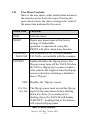
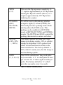
1
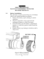
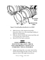
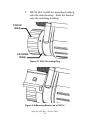
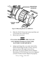
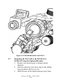
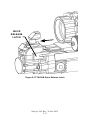
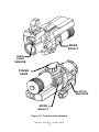
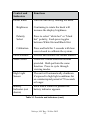
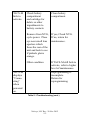
P/N 830-0037-0
OSR 11-S-2164
OPERATOR MANUAL
TACS-MTM
Thermal Acquisition Clip-on System - Miniature
Nivisys, LLC
400 S. Clark Drive
Suite 105
Tempe, AZ 85281 USA
480-970-3222 (tel)
480-970-3555 (fax)
[email protected]
www.nivisys.com
Export of the commodities described herein is strictly prohibited without a valid
export license issued by the U.S. Department of State Office of Defense Trade
Controls prescribed in the International Traffic in Arms Regulations (ITAR) Title 22,
Code of Federal Regulation, Chapter 1, Subchapter M, Parts 120-130.
Inside cover intentionally left blank.
OPERATOR
MANUAL
FOR
TACS-M
TM
Thermal Acquisition Clip-on System - Miniature
ALL RIGHTS RESERVED
This document contains information developed by Nivisys,
LLC. It has been prepared to instruct Nivisys customers in
the proper care and operation of the equipment respective to
this document. Neither receipt nor possession thereof confers
any right to reproduce or use, or disclose, in whole or in part,
any such information without written authorization from
Nivisys, LLC. © Nivisys 2011.
Nivisys, LLC Rev. 20 Nov 2012
i
This page intentionally left blank.
Nivisys, LLC Rev. 20 Nov 2012
ii
ADVISORY OVERVIEW
The following description categorizes the level of risk
associated with each cautionary statement displayed
throughout the manual.
WARNING
highlights an operation
or procedure which, if not
strictly observed, could
result in injury to or death of
personnel.
CAUTION
highlights an operation
or procedure which, if not
strictly observed, could
result in damage to or
destruction of equipment or
loss of mission effectiveness.
NOTE
highlights an essential
operation, procedure,
condition or statement.
Nivisys, LLC Rev. 20 Nov 2012
iii
This page intentionally left blank.
Nivisys, LLC Rev. 20 Nov 2012
iv
Table of Contents
Advisory Overviewiii
Table of Contentsv
List of Figuresvii
List of Tablesix
CHAPTER 1: GENERAL INFORMATION
1-1
1.1
Introduction1-1
1.2
Equipment Description
1-1
1.3
Standard Kit Parts List
1-2
1.4
Standard Kit Parts Illustration
1-3
1.5
Optional Items List
1-4
1.6
Optional Items Illustration
1-4
1.7
System Performance and Data
1-5
CHAPTER 2: preparation for use 2-1
2.1
Introduction2-1
2.2
Battery Precautions2-1
2.3
Battery Installation2-2
2.4
TACS-M Mounting Bracket
2-3
2.5
Mounting the TACS-M to the
PVS-15/15A, NVAG and PVS-18
2-5
2.6
Mounting the TACS-M to the
PVS-7B/D, PVS-14/14A, MUM-14A
and PVS-232-7
2.7
Mounting the TACS-M to the MUM-14 or NVBS-15 Using the
Optional Bracket2-10
2.8
TACS-M Quick Release Latch
2-12
Nivisys, LLC Rev. 20 Nov 2012
v
Table of Contents (cont.)
CHAPTER 3: operating instructions 3-1
3.1
Introduction3-1
3.2
Controls and Indicators
3-1
3.3
Powering ON/OFF the TACS-M
3-4
3.4
Brightness Control3-4
3.5
Operation Modes3-4
3.6
Polarity (White-Hot, Black-Hot)
3-5
3.7
Calibration3-5
3.8
Battery Indicator3-6
3.9
Flip-Up Sensor3-6
3.10
Activating the User Menu
3-7
3.11
User Menu Controls
3-8
3.12
Preparation for Storage
3-11
chapter 4: mAINTENANCE instructions 4-1
4.1
Introduction4-1
4.2
Preparation for Maintenance
4-1
4.3
Cleaning the TACS-M
4-1
4.4
Cleaning the Optics
4-2
4.5
Checking for Damage and Corrosion
4-2
CHAPTER 5: troubleshooting
5.1
Troubleshooting Procedures
5-1
5-1
Appendix A: Spare and repair parts listA-1
A.1
IntroductionA-1
A.2
Contact InformationA-1
A.3
Spare Parts List
A-1
Appendix B: Warranty InformationB-1
Nivisys, LLC Rev. 20 Nov 2012
vi
List of FIGURES
FIGURE DESCRIPTION
PAGE
1-1 Standard Kit Parts Illustration
1-3
1-2
Optional Items Illustration 1-4
2-1
Battery installation2-2
2-2
Standard Mounting Bracket
2-4
2-3
Optional Mounting Bracket
2-4
2-4
Installing Bracket to a
PVS-15/15A and PVS-18
2-5
2-5
Installing Mounting Bracket to an NVAG 2-6
2-6
Mounting the TACS-M to a
PVS-15/15A, PVS-182-7
2-7
PVS-14 Locking Ring
2-8
2-8
Mounting Bracket on a PVS-14
2-8
2-9
Mounting Bracket on a MUM-14A
2-9
2-10
TACS-M Mounted to the PVS-14
2-10
2-11
Optional Mounting Bracket on
the MUM-142-11
2-12
TACS-M Mounted to the MUM-14
2-12
2-13
TACS-M Quick Release Latch
2-13
3-1 Controls and Indicators
3-2
3-2
User Menu3-7
Nivisys, LLC Rev. 20 Nov 2012
vii
This page intentionally left blank.
Nivisys, LLC Rev. 20 Nov 2012
viii
List of Tables
TABLE DESCRIPTION
PAGE
1-1 Standard Kit Parts List
1-2
1-2 Optional Items List
1-4
1-3 System Performance and Data
1-5
3-1 Controls and Indicators
3-3
3-2 Menu Controls
3-8
5-1 Troubleshooting5-1
A-1 Spare and Repair Parts List
A-1
Nivisys, LLC Rev. 20 Nov 2012
ix
This page intentionally left blank.
Nivisys, LLC Rev. 20 Nov 2012
x
CHAPTER 1:
GENERAL INFORMATION
1.1Introduction:
This manual provides operation and maintenance
instructions for the TACS-M. It also provides
specifications and data on the performance of the
TACS-M. To ensure the safety of the operator
and the correct operation of the TACS-M it is
recommended that this manual is read carefully in its
entirety before any deployment or field application.
1.2
Equipment Description:
The TACS-M provides the user the ability to
enhance the functionality of currently fielded night
vision goggles (AN/PVS-7B/D, AN/PVS-14/14A,
AN/PVS-15/15A, AN/PVS-18, AN/PVS-23, MUM14/14A and other image intensification (I2) goggles).
The TACS-M adds a thermal image overlay to the I2
scene without modifying hardware, thus providing
situational awareness in extreme low light, no light,
or foliated conditions where I2 devices have some
limitations. At the core of the TACS-M is a Long
Wave Infrared (LWIR) 320 x 240 pixel Focal Plane
Array (FPA). This LWIR sensor measures thermal
radiation in the 8-12 micron wavelengths.
The FPA video is processed and displayed on the
internal micro-display, then optically projected
into the night vision goggles (NVG). The TACS-M
attaches to the host NVG with a bracket that
Nivisys, LLC Rev. 20 Nov 2012
1-1
clamps to the body of the night vision device and
sits directly in front of the NVG’s front lens. The
TACS-M is powered by one (1) internal lithium-123
battery located in the integrated battery compartment
and features a quick disconnect built into the
clamping hardware.
1.3
Standard Kit Parts List:
The standard TACS-M kit comes with the items
listed in the following table.
Item
Part No.
Description
Qty.
1
8200-100
TACS-M
1
2
106-0029-0
Standard Mounting Bracket 1
3
220-0012-0
Mounting Bushing
1
4
580-0002-0
CR123 Lithium Battery
2
5
111-0008-0
Soft Carrying Case
1
6
170-14
Lens Cloth
1
7
830-0037-0
Operator Manual
1
8
830-0038-0
Quick Reference Guide
(QRG)
1
Table 1-1 Standard Kit Parts List
Nivisys, LLC Rev. 20 Nov 2012
1-2
1.4
Standard Kit Parts Illustration:
The illustration below is provided for quick
identification of the standard parts of the TACS-M
kit.
Figure 1-1 Standard Kit Parts Illustration
Nivisys, LLC Rev. 20 Nov 2012
1-3
1.5
Optional Items List:
The TACS-M is compatible with the following
optional accessory listed in the following table.
Item
Part No.
Description
Qty.
1
106-0042-0
TACS-M to MUM-14
Mounting Bracket
1
Table 1-2 Optional Items List
1.6
Optional Items Illustration:
The illustration is provided as a visual key to
optional items that can be used with the standard
TACS-M.
Figure 1-2 Optional Items Illustration
Nivisys, LLC Rev. 20 Nov 2012
1-4
1.7
System Performance and Data:
The chart below lists the technical specifications and
data of the TACS-M system. The data contained
herein is subject to change without notice.
ITEM
LIMITS
Electrical
Power Source
Battery (1.5V DC max.)
Battery Requirements
1 CR123 Lithium
Battery Life
2.5 hrs @ 23°C (73°F)
Physical
Dimensions
3.8cm x 6.4cm x 8.9
(1.5” x 2.5” x 3.5”)
Weight (with battery)
150g (5.3 oz)
Optical
Magnification
1.0X
Field of View
20° (circular)
Sensor
320 x 240 VOx
uncooled LWIR
microbolometer
Spectral Response
8-12 µm
Pitch
25 µm
NEΔT
50 mk
Table 1-3 System Performance and Data
Nivisys, LLC Rev. 20 Nov 2012
1-5
Performance
Range, Clear
Detection: 300 m
Range, Obscured
Detection: 250 m
Environmental
Operating Temperature
0° C to 50° C
(32° F to 122° F)
Storage Temperature
-40° C to 50° C
(-40° F to 122° F)
Maximum Operating Altitude
9144 m (30,000 ft)
Maximum Storage Altitude
12192 m (40,000 ft)
Maximum Immersion (1 hr)
20m (66 ft)
Table 1-2 System Performance and Data (cont.)
Nivisys, LLC Rev. 20 Nov 2012
1-6
CHAPTER 2:
PREPARATION FOR USE
2.1Introduction:
This section contains instructions for installing and
attaching various components and accessories to the
TACS-M for operation under normal conditions.
2.2Battery Precautions:
Warning
Inspect batterY for bulging
prior to use. If the battery
shows signs of bulging, do not
use.
Warning
DO NOT HEAT, PUNCTURE,
DISASSEMBLE, SHORT CIRCUIT,
Incinerate, ATTEMPT TO
RECHARGE OR OTHERWISE
TAMPER WITH THE BATTERy.
Warning
TURN OFF the TACS-M IF the
BATTERYCOMPARTMENT BECOMES
UNDULY HOT.
IF POSSIBLE, WAIT UNTIL THE
BATTERy HAS COOLED BEFORE
REMOVING THEM.
Nivisys, LLC Rev. 20 Nov 2012
2-1
CAUTION
Obey the battery
manufacturer directions for
battery disposal.
2.3Battery Installation:
The electronic circuit is powered by one (1) Lithium
CR123 cell. Install the battery as follows.
1. Remove the battery cap by turning it counterclockwise.
2. Check to ensure the o-ring is present and
undamaged. Replace o-ring if necessary.
3. Insert the battery into the battery compartment,
negative (-) ends first, positive ends toward the
battery cap.
4. Replace battery cap, turning it clockwise until a
stop occurs.
battery cap
positive
terminal
Figure 2-1 Battery installation
Nivisys, LLC Rev. 20 Nov 2012
2-2
2.4
TACS-M Mounting Bracket:
Nivisys provides a standard mounting bracket with
bushing for the TACS-M to adapt to different night
vision equipment including: AN/PVS-7B/D, AN/
PVS-14/14A, and AN/PVS-23, MUM-14A, NVAG,
AN/PVS-15/15A and AN/PVS-18.
An optional mounting bracket is available for use
with the MUM-14 and NVBS-15.
NOTE
If the mounting bracket is
loose, the over-center latch
can be tightened on its screw to
increase latching tension.
CAUTION
Over-tightening the clamping
mechanism may result in
damage to the
NIGHT VISION DEVICE.
NOTE
Check to confirm the close
focus setting of the NVG
works correctly. The
position of the clamp should
be adjusted to allow for the
full focus range on the NVG.
Nivisys, LLC Rev. 20 Nov 2012
2-3
OVER-CENTER
LATCH
mounting
BUSHING
clamp
BASE
catch
Figure 2-2 Standard Mounting Bracket
OVER-CENTER
LATCH
clamp
BASE
gripping
tabs
catch
Figure 2-3 Optional Mounting Bracket
Nivisys, LLC Rev. 20 Nov 2012
2-4
2.5
Mounting the TACS-M to the PVS-15/15A, NVAG
and PVS-18:
1. Set the correct interpupillary adjustment for the
night vision device.
2. Turn the objective lens focus ring to the infinity
focus position (all the way in).
3. Fit the mounting bushing over the objective lens
of the night vision device.
focus
ring
MOUNTING
bushing
objective
lens
Figure 2-4 Installing Bracket to a PVS-15/15A and PVS-18
note
MOunting Bushing is not
required for use with nvag.
Nivisys, LLC Rev. 20 Nov 2012
2-5
focus
ring
objective
lens
Figure 2-5 Installing Mounting Bracket to an NVAG
4. With the base of the bracket toward the
binocular, slide it over the mounting bushing or
objective lens housing.
5. Slide the TACS-M into the bracket until the unit
is secured by the catch/release.
6. Orient TACS-M unit as desired.
note
When orienting the
mounting bracket, check
that peripheral vision is as
unobstructed as possible.
7. Adjust and clamp the over-center latch of the
TACS-M mounting bracket securely onto the
objective lens of the night vision device.
Nivisys, LLC Rev. 20 Nov 2012
2-6
Figure 2-6 Mounting the TACS-M to a PVS-15/15A, PVS-18
2.6
Mounting the TACS-M to the PVS-7B/D, PVS14/14A, MUM-14A and PVS-23:
1. Remove any head mount or helmet mount
adapters.
2. Turn the objective lens focus ring to the infinity
focus position (all the way in).
3. Attach the mount bracket:
A. PVS-7B/D, PVS-14/14A : With the base
of the bracket facing away from the night
vision device, slide the bracket onto the
objective locking ring.
B. PVS-23: Slide bracket onto objective lens.
Nivisys, LLC Rev. 20 Nov 2012
2-7
C. MUM-14A: Install the mounting bushing
onto the main housing. Slide the bracket
onto the mounting bushing.
focus
ring
locking
ring
Figure 2-7 PVS-14 Locking Ring
Figure 2-8 Mounting Bracket on a PVS-14
Nivisys, LLC Rev. 20 Nov 2012
2-8
mounting
bushing
focus
ring
Figure 2-9 Mounting Bracket on a MUM-14A
4. Slide the TACS-M into the bracket until the unit
is secured by the catch/release.
5. Orient unit as desired.
NOTE
PVS-14/14A requires the TACS-M
unit be rotated against the
battery compartment.
6. Adjust and clamp the over-center latch of the
TACS-M mounting bracket securely onto the
objective lens of the night vision device.
7. Re-install any head or helmet mount adapters.
Orientation of TACS-M may have to be adjusted
so head or helmet mount adapters fit properly.
Nivisys, LLC Rev. 20 Nov 2012
2-9
Figure 2-10 TACS-M Mounted to the PVS-14
2.7
Mounting the TACS-M to the MUM-14 or
NVBS-15 Using the Optional Bracket:
1. Remove any head mount or helmet mount
adapters.
2. Turn the objective lens focus ring to the infinity
focus position (all the way in).
3. With the base of the bracket facing away from
Nivisys, LLC Rev. 20 Nov 2012
2-10
the night vision device, slide the bracket over
the objective locking ring so that both gripping
tabs engage.
Optional
mount
base
locking
ring
gripping
tabs
Figure 2-11 Optional Mounting Bracket on the MUM-14
4. Slide the TACS-M into the bracket until the unit
is secured by the catch/release.
5. Orient TACS-M as desired.
6. Adjust and clamp the over-center latch of the
TACS-M mounting bracket securely onto the
objective lens of the night vision device.
7. Re-install any head or helmet mount adapters.
Orientation of TACS-M may have to be adjusted
so head or helmet mount adapters fit properly.
Nivisys, LLC Rev. 20 Nov 2012
2-11
Figure 2-12 TACS-M Mounted to the MUM-14
2.8
TACS-M Quick Release Latch:
Perform the following procedure to remove the
TACS-M unit from the installed mounting bracket:
1. Locate the quick release latch on the TACS-M
unit.
2. Press the quick release latch and slide the
TACS-M away from the night vision device.
Nivisys, LLC Rev. 20 Nov 2012
2-12
Quick
Release
Latch
Figure 2-13 TACS-M Quick Release Latch
Nivisys, LLC Rev. 20 Nov 2012
2-13
This page intentionally left blank.
Nivisys, LLC Rev. 20 Nov 2012
2-14
CHAPTER 3:
Operating instructions
3.1Introduction:
This chapter contains instructions for the
safe operation of the TACS-M under normal
circumstances and environments.
3.2
Controls and Indicators:
The controls and indicators for the TACS-M are
shown in Figure 3-1 and are described in Table 3-1.
CAUTION
Do not point the TACS-M at the
sun or allow direct sunlight
to shine directly upon the
objective lens.
To protect the system, keep
the lens cap in place when
not in use.
Be careful not to touch
the optical surfaces. If
fingerprints or contaminants
are present, use the provided
lens cloth for cleaning.
Table 3-1 Controls and Indicators
Nivisys, LLC Rev. 20 Nov 2012
3-1
MODE
SELECT
high
light
sensor
power
knob
Latch
Release
MODE
SELECT
Figure 3-1 Controls and Indicators
Nivisys, LLC Rev. 20 Nov 2012
3-2
Control and
Indicators
Functions
Power Knob
Turn the unit on by rotating the knob.
Brightness
Continuing to rotate the knob will
increase the display brightness.
Polarity
Select
Press to select “white hot” or “black
hot” polarity, Each press toggles
between White Hot and Black Hot.
Calibration
Press and hold for 3 seconds with lens
cover closed to calibrate the system.
Latch Release
Secures and releases the mount bracket.
Mode Select
There are 2 mode selection buttons
provided. Both perform the same
function. Press to cycle through
viewing modes.
High Light
Sensor
The unit will automatically shutdown
if exposed to high light conditions for
an uninterrupted period of 70 seconds
or longer.
Battery
Indicator (not
shown)
Each time a control is pressed the
battery indicator appears.
Table 3-1 Controls and Indicators (cont.)
Nivisys, LLC Rev. 20 Nov 2012
3-3
3.3
Powering ON/OFF the TACS-M:
NOTE
When the TACS-M is on, a
thermal image overlay is
viewed through the NVG.
Upon power off, the unit has
a 3 second delay before it can
be powered on again.
1. The TACS-M is powered ON or OFF by rotating
the knob on the bottom of the unit.
3.4Brightness Control:
Rotate the power knob to increase and decrease the
display brightness.
3.5
Operation Modes:
There are three modes available in the TACS-M:
• Full Thermal: high thermal sensitivity.
• Patrol: low thermal sensitivity.
• Outline: outlines thermal targets, allowing a higher resolution I2 imagery to be viewed in conjunction with the TACS-M thermal outline overlay.
Each press of either mode select button cycles
through the three modes: from Full Thermal, to
Patrol, to Outline.
Nivisys, LLC Rev. 20 Nov 2012
3-4
3.6
Polarity (White-Hot, Black-Hot):
To select “white hot” or “black hot” polarity, press
the power knob. Each press toggles between White
Hot and Black Hot.
In Patrol and Full Thermal modes, “white hot” shows
hot thermal targets as white and “black hot” shows
hot thermal targets as black.
In Outline mode, the Polarity selection does not
affect the image.
nOTE
If the TACS-m is turned off
using the power knob prior to
the battery being removed,
the TACS-M will retain the
last user settings for Mode
and Polarity.
3.7Calibration:
If the thermal image appears degraded, perform
calibration as follows:
1. Place the lens cap, hand, or any thermally
uniform object over the TACS-M objective lens.
2. Press and hold the power knob for 3 seconds,
until “CALIBRATION” shows in the image.
NOTE
Calibrating without
covering the objective lens
will result in a static ImagE.
Nivisys, LLC Rev. 20 Nov 2012
3-5
If this occurs, cover the
objective lens and
re-calibrate.
3.8Battery Indicator:
The battery status indicator appears each time a
control is pressed, or when there is a battery status
change. Once the battery indicator is empty, the
TACS-M will have at least 20 minutes of operating
time remaining. With 1 minute of operational time
remaining, “CRIT BATT” will appear in the image.
NOTE
To retain modified user
settings, power down the
system before removing the
battery.
3.9
Flip-Up Sensor:
The flip-up controls are found in the user menu
under “FLIPDLY” and are used to automatically
shut off the unit upon a “flip-up” motion for helmet
mounted applications. The flip-up sensor detects
orientation of the TACS-M when initially powered
on. When the unit is shut off because of the flip-up
sensor a “FLIP-OFF” appears before shut down.
For best results, turn the TACS-M on when looking
forward and level. If the unit is pointing down when
powered on, normal horizontal use may be detected
as a “flip-up”. To correct, cycle the power while
looking straight ahead. If “FLIP-OFF” is displayed
during normal operation, increasing the SENS value
Nivisys, LLC Rev. 20 Nov 2012
3-6
3.10
will reduce or eliminate the occurrence. Setting the
SENS value too high will result in the TACS-M not
shutting down and may greatly reduce battery life.
Activating the User Menu:
The TACS-M is equipped with a user menu allowing
each user to customize their unit. To activate the
user menu, press either mode button and hold for 5
seconds. The user menu will appear. If no button is
pressed for a continuous 10 seconds, the user menu
will automatically exit. The options shown in the
image below are the factory defaults.
Figure 3-2 User Menu
Nivisys, LLC Rev. 20 Nov 2012
3-7
3.11
User Menu Controls:
Once in the user menu, either mode button advances
the selection arrow down the menu. Pressing the
power knob selects the item or changes the value of
the menu item indicated by the arrow.
Menu Item
Functions
EXIT
Exits the menu
RESET
Resets user menu items to the factory
settings. If undesirable
operation is experienced, using this
RESET will often return basic function.
COMPASS/
MAGVAR
Not Available (N/A). Nivisys standard
TACS-M is not installed with the compass.
FLIPDLY
Enables/Disables the flip-up sensor. The
Flip-up sensor turns off the TACS-M when
the NVG is flipped up to conserve battery.
Also controls the length of time the flip-up
sensor waits before initiating a shutdown
due to “flip-up”.
OFF
15s, 30s,
1m, 2m
Disables the “flip-up” sensor.
The flip up sensor must exceed the flip-up
angle for the time shown before shutting
down. For three (3) seconds prior to
shutting down, the TACS-M will display
“FLIP OFF”. Looking back at the horizon
will reset the flip-up timer.
Table 3-2 Menu Controls
Nivisys, LLC Rev. 20 Nov 2012
3-8
SENS
(1-5)
This sets the flip-up sensor sensitivity. A
‘1’ requires approximately a 90º flip before
starting the flip-off counter (above). A ‘5’
requires approximately 170º flip before
initiating the counter.
PULSING
(OFF,
OUTLINE,
BOTH)
To aid the user in determining whether
a target is light (I2) or heat (LWIR), the
TACS-M provides a pulsing mode which
slowly pulses the LWIR scene. This
pulsing can be available in OUTLINE
mode or BOTH (OUTLINE and PATROL)
modes. The DEPTH and RATE control the
pulsing characteristics and are set below.
DEPTH
(10%, 20%,
…, 100%)
The depth controls how dim the LWIR
image gets during a pulse. 10% is a slight
change in brightness. 100% pulses from
white to black and back to white in the
time listed below. The factory default is
30%, which is easily seen, but the image is
not lost during a pulse.
RATE
(1, 2, 4, 6, 8)
The RATE controls how long each pulse
is (in seconds). A ‘1’ is a fast pulse of once
per second. An ‘8’ takes eight seconds per
pulse. The factory default is ‘4’, which
provides one pulse every 4 seconds.
Table 3-2 Menu Controls (cont.)
Nivisys, LLC Rev. 20 Nov 2012
3-9
ABC
(OFF, ON)
Activates the Automatic Brightness
Control. This control changes the display
brightness based on ambient scene
brightness. In varying light conditions, this
feature reduces the need for the user to
change the brightness. For the best effect,
set the brightness near the middle of the
adjustment range.
NOTE
For best performance with ABC
turned on, set the brightness
in the middle of the brightness
range. The TACS-M will auto-adjust
the brightness for all lighting
conditions when set correctly.
NOTE
With ABC set to “ON”, the brightness
control may appear to have
limited function at the top or
bottom of the range, depending
on light level. This occurs
because the ambient light sensor
is controlling the output and is a
normal occurrence. To have direct
control over the brightness, set
the ABC to “OFF”.
Table 3-2 Menu Controls (cont.)
Nivisys, LLC Rev. 20 Nov 2012
3-10
GAIN
(-8, -7,
AUTO, …,
+7, +8)
This setting increases or decreases the
gain to provide higher or lower sensitivity
depending on environmental conditions.
Increasing the gain results in more contrast
(black/white) in the image.
OFFSET
(-8, -7,
AUTO, …,
+7, +8)
This value changes the thermal camera
offset. While the value is stored, it is only
active during manual gain operation.
Decreasing this value will reduce the
number of saturated pixels.
ROT 180º
Rotates the symbology 180º for operation
with the TACS-M in the upside down
orientation.
Table 3-2 Menu Controls (cont.)
3.12
Preparation for Storage:
1. Power down the TACS-M
2. Packaging after use
A. Remove battery.
B. Inspect the battery housing for corrosion or
moisture. Clean and dry if necessary.
C. Place the TACS-M and accessories into the
soft carrying case.
D. Return to storage area.
NOTE
Prior to placing the TACS-M
into the carrying case,
ensure it is free of dirt, dust,
and moisture.
Nivisys, LLC Rev. 20 Nov 2012
3-11
This page intentionally left blank.
Nivisys, LLC Rev. 20 Nov 2012
3-12
CHAPTER 4:
Maintenance instructions
4.1Introduction:
The TACS-M is designed to be used in diverse
environments and rugged conditions. However,
it is recommended to that regular and simple
maintenance is performed for optimal system
performance.
CAUTION
The TACS-M is a precision
electro-optical instrument
and must be handled
carefully.
Do not scratch the external
lens surfaces or touch them
with your fingers.
4.2
Preparing for Maintenance:
Before performing any maintenance or cleaning
of the system, remove all power sources from the
TACS-M including batteries and/or external power
supplies.
4.3
Cleaning the TACS-M:
When necessary, use a moistened clean cloth to
wipe the outside of the unit, EXCEPT FOR THE
OPTICAL SURFACES. Be sure to wipe away
excess dirt and dust that may restrict the performance
Nivisys, LLC Rev. 20 Nov 2012
4-1
of and damage moving and mating parts. If needed,
the use of a very diluted detergent solution is
permissible. Dry with a soft clean cloth, or allow unit
to air-dry before storing it.
4.4
Cleaning the Optics:
When cleaning of the lens is required, first blow
any loose dirt or grit away from the surface of the
lens. Use the supplied lens cloth lightly moistened
with water or lens cleaning fluid to lightly wipe the
optical surfaces, using a circular motion. Dry with a
clean and dry lens cloth.
4.5
Checking for Damage and Corrosion:
As a general guideline, conduct an inspection of the
TACS-M, accessories, and the case after every use.
Look for heavy wear and cracks in rubber or plastic.
Inspect for moisture or corrosion in the battery
compartment. Check for scratches, condensation and
foreign matter on optical surfaces. Report missing or
damaged items, for replacement.
Nivisys, LLC Rev. 20 Nov 2012
4-2
CHAPTER 5:
TROUBLESHOOTING
5.1
Troubleshooting Procedures:
Table 5-1 lists common malfunctions that may occur
with the TACS-M. Perform the tests, inspections
and corrective actions in the order they appear in the
table.
This table cannot list all the malfunctions that may
occur, all the tests and inspections needed to find the
fault, or all the corrective actions needed to correct
the fault. If the equipment malfunction is not listed
or actions listed do not correct the fault, notify your
maintainer.
Problem
Test or Inspection
Corrective Action
TACS-M
fails to
activate.
Check that lens
cover is not
covering objective
lens.
Remove lens cover
from objective lens.
Check Battery.
Replace with new
battery.
Table 5-1 Troubleshooting
Nivisys, LLC Rev. 20 Nov 2012
5-1
TACS-M
fails to
activate.
TACS-M
displays
“Connecting”
when
powered
on.
Check battery
compartment
and cartridge for
debris or other
impediments to
battery contacts.
Clean battery
compartment.
Remove from NVG,
cycle power. Place
eye near small lens
aperture which
faces the rear of the
unit and look to see
if pinhole glows
orange.
If yes, Check NVG.
If no, return for
maintenance.
Other condition
If TACS-M still fails to
activate, refer to higher
level of maintenance.
Reprogramming is
incomplete.
Return for
reprogramming
Table 5-1 Troubleshooting (cont.)
Nivisys, LLC Rev. 20 Nov 2012
5-2
Thermal
image is
degraded.
Check objective
and display head
for debris, smudges,
scratches, etc.
Clean with lens cloth.
Check if the
calibration includes
static image.
Perform Calibration
with cover over
objective.
Actuate RESET
under user menu.
If no improvement,
Return for maintenance
Table 5-1 Troubleshooting (cont.)
Nivisys, LLC Rev. 20 Nov 2012
5-3
This page intentionally left blank.
Nivisys, LLC Rev. 20 Nov 2012
5-4
APPENDIX A:
SPARE AND REPAIR PARTS LIST
A.1Introduction:
This section provides information needed to identify,
contact and order spare and/or repair parts for the
TACS-M.
A.2
Contact Information:
To order spare or repair parts for the TACS-M or any
of your night vision products contact:
Nivisys, LLC
400 S. Clark Drive, Suite #105
Tempe, Arizona 85281 USA
Phone: 1-480-970-3222
Fax: 1-480-970-3555
A.3
Spare Parts List:
The following is a list of parts that may be ordered
for spare parts for the TACS-M.
Part No.
Description
Qty.
8200-100
TACS-M
1
106-0029-0
Standard Mounting Bracket
1
CR123 Lithium Battery
1
580-0002-0
Table A-1 Spare and Repair Parts List
Nivisys, LLC Rev. 20 Nov 2012
A-1
170-14
Lens Cloth
1
830-0037-0
Operator Manual
1
830-0038-0
Quick Reference Guide (QRG)
1
111-0008-0
Soft Carrying Case
1
220-0007-0
Lens Cover
1
310-0001-1
Battery Cap
1
220-0012-0
Mounting Bushing
1
Table A-1 Spare and Repair Parts List (cont.)
Nivisys, LLC Rev. 20 Nov 2012
A-2
APPENDIX B:
WARRANTY INFORMATION
Equipment Warranties And Remedy:
Seller warrants that each newly manufactured item sold
hereunder and such portion of a repaired/refurbished item as
has been repaired or replaced by Seller under this warranty,
shall be free from defects in material or workmanship at
the time of shipment and shall perform during the warranty
period in accordance with the specifications incorporated
herein. Should any failure to conform to these warranties
be discovered and brought to Seller’s attention during the
warranty period and be substantiated by examination at
Seller’s factory or by authorized field personnel, then at
its own cost, Seller shall correct such failure by, at Seller’s
option, repair or replacement of the non-conforming item
or portion thereof, or return the unit purchase price of the
non-conforming item or component. Buyer agrees that this
remedy shall be its sole and exclusive remedy against Seller
and that no other remedy shall be available or pursued by
Buyer against Seller. In no event shall the Seller be liable
for any cost or expense in excess of those described in this
paragraph and expressly excluding any liability or damages
for special, incidental or consequential damages.
The warranty period for newly-manufactured items shall
extend 12 months from the date of shipment by Seller unless
a different warranty period is agreed in writing to by Seller.
The warranty period for repaired/refurbished electronic
components shall extend for the unexpired warranty period or
90 days, whichever is longer, of the item repaired or replaced.
Nivisys, LLC Rev. 20 Nov 2012
B-1
This warranty shall not extend to any item that upon
examination by Seller is found to have been subject to:
E. Mishandling, misuse, negligence or accident.
F. Installation, operation or maintenance that
either was not in accordance with Seller’s
specifications and instructions, or otherwise
improper.
G. Tampering, as evidenced, for example, by
broken seals, damaged packaging containers,
etc.
H. Repair or alteration by anyone other than
Seller without Seller’s express advance written
approval.
Failure to promptly notify Seller in writing upon discovery
of any non-conforming item during the warranty period shall
void the warranty as to such item. Buyer shall describe any
such non-conformity in detail, expressing its position as to
return of any article under the remedy provided herein. No
returns shall be accepted without prior approval by Seller.
Return Material Authorization Number (RMA#):
Warranty and non-warranty items returned to Nivisys for repair
or replacement require a RMA#. Email support@nivisys.
com, call 1-480-970-3222 or fax 1-480-970-3555 with a serial
number and detailed information to obtain a RMA#.
Nivisys, LLC Rev. 20 Nov 2012
B-2
THIS WARRANTY IS EXCLUSIVE
AND IN LIEU OF ANY OTHER
WARRANTY, EITHER EXPRESSED OR
IMPLIED, INCLUDING WARRANTIES
OF MERCHANTABILITY OR FITNESS
FOR A PARTICULAR PURPOSE.
Nivisys, LLC Rev. 20 Nov 2012
B-3
This page intentionally left blank.
Nivisys, LLC Rev. 20 Nov 2012
B-4
Inside cover intentionally left blank.
Nivisys, LLC
400 S. Clark Drive, Suite 105
Tempe, Arizona 85281 USA
nivisys.com