1
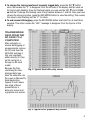
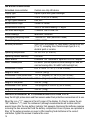
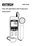
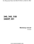
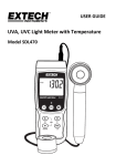
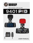
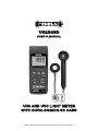
UV254SD
USER’S MANUAL
UVA AND UVC LIGHT METER
WITH DATALOGGING SD CARD
Please read this manual carefully and thoroughly before using this product.
TABLE OF CONTENTS
Introduction . . . . . . . . . . . . . . . . . . . . . . . . . . . . . . . . . 3
Key Features . . . . . . . . . . . . . . . . . . . . . . . . . . . . . . . . 3
Operating Instructions . . . . . . . . . . . . . . . . . . . . . . 4 – 9
What’s in the case . . . . . . . . . . . . . . . . . . . . . . . 4
Setup . . . . . . . . . . . . . . . . . . . . . . . . . . . . . . . 5 – 6
Normal Operation . . . . . . . . . . . . . . . . . . . . . . . . 7
Holding and Storing Measurements. . . . . . . . . . 8
Automatic vs. Manual Datalogging . . . . . . . 8 – 9
Transferring Data from the SD Card
to a Computer . . . . . . . . . . . . . . . . . . . . . . . . . . . 9
Specifications . . . . . . . . . . . . . . . . . . . . . . . . . . . . . . 10
Maintenance & Troubleshooting Tips . . . . . . . . 10 – 11
Replacement Parts & Optional Accessories . . . . . . . 11
Warranty Information . . . . . . . . . . . . . . . . . . . . . . . . 11
Return for Repair Policy . . . . . . . . . . . . . . . . . . . . . . 11
2
INTRODUCTION
Thank you for purchasing General Tools & Instruments’ UV254SD UVA and UVC Light Meter
with Datalogging SD Card. Please read this user’s manual carefully and thoroughly before
using the instrument.
Many industrial and commercial applications require or can benefit from measurement of
the intensity of UVA and/or UVC light. Among them are welding (to minimize exposure to
“blue light” radiation), UV sterilization of food, photochemical matching, erasure of
electrically programmable read-only memory (EPROM) chips, production of graphic arts
products, exposure of photoresists, and curing of inks, adhesives and coatings.
The UV254SD has the performance and features needed to satisfy the most demanding
aspects of these applications. For example, it combines the capabilities of UVA (black light
in the long-wave 365-nm band) and UVC (short waves in the 254-nm band) measurement
in one instrument. The meter also can measure surface temperature, if mated with a Type K
or Type J thermocouple. A UVA probe and a UVC probe are supplied with the instrument.
Because it is microprocessor-based, the UV254SD can make full use of the portability,
reliability and large storage capacities that SD memory cards offer. Measurements of light
intensity or temperature can be made automatically at any of 11 sampling rates between
one second and one hour. After time-stamping and storing the measurements on an SD
card plugged into the instrument (a process called datalogging), the user can remove the
card and transfer the measurements to a laptop or desktop computer either directly or via a
USB card reader.
The UV254SD has a backlit 2-1/2 in. diagonal display and is powered by six “AA” Alkaline
batteries or an optional 9-VDC AC adapter.
KEY FEATURES
• Includes UVA and UVC probes
• Measures light intensity within two automatically switched full-scale ranges:
2 mW/cm2 and 20 mW/cm2
• Displays maximum and minimum readings
• Performs real-time automatic datalogging at sampling time settable from
1 second to 1 hour
• Also supports manual logging and changing of card storage location
• Comes with 2 GB SD memory card, but works with cards up to 16 GB
• Big (2.5 in. diagonal) front-panel green backlit LCD is easy to read
• Auto power off function
• Powered by six “AA” batteries or 9V AC/DC adapter
3
OPERATING INSTRUCTIONS
WHAT’S IN THE CASE
The UV254SD comes fully assembled in a carrying case along with a UVA probe, a UVC
probe, a 2 GB SD memory card and this user’s manual.
Figure 1 shows all of the controls and indicators on the front, back, top, bottom and right
side of the UV254SD. It also shows the main components of the supplied UVA and UVC
probes. Familiarize yourself with their positions and functions before moving on to the setup
procedure.
TOP
FRONT
BOTTOM
RIGHT
SIDE
BACK
UVC
PROBE
UVA
PROBE
Fig. 1. The controls and indicators and other physical features of the UV254SD and its
two supplied probes
1-12 Socket for 9VDC AC adapter
1-1 Liquid-crystal display
1-13 Battery compartment cover
1-2 POWER/ESC button
1-14 Battery compartment cover screws
1-3 FUNC./HOLD/NEXT button
1-15 Kickstand
1-4 REC/ENTER button
1-16 Tripod attachment nut
1-5 SET ▼ button
1-17 UVC probe plug
1-6 LOGGER ▲ button
1-18 UVC sensor housing
1-7 Socket for UVA and UVC probes
1-19 UVC sensor
1-8 Socket for Type K or Type J
thermocouple
1-20 UVA probe handle
1-9 SD card socket
1-21 UVA sensor
1-10 RS232 output jack
1-22 UVA probe plug
1-11 RESET button
1-23 UVA sensor cap
4
SETUP
1. Choose the power source. Before using the UV254SD, be sure it is powered by fresh
batteries or an optional 9VDC AC adapter plugged into the bottom jack on its right side
(callout 1-12).
To remove the battery compartment cover, remove the two screws holding it in place
(callout 1-14). Then install six “AA” batteries in the correct orientation, using the polarity
marks on the inside of the compartment as a guide. Replace the cover by replacing the
two screws.
2. Install an SD card. To prepare for setup, also install the supplied 2 GB SD memory card
or another card with a capacity from 1 GB to 16 GB in the socket on the bottom of the
UV254SD (callout 1-9). When installing the card, make sure its gold contacts are facing
front and push the card into the socket until you hear a click. To remove the card, push it
in until you hear a click and the card pops out.
Now power on the instrument by pressing the POWER/ESC button (callout 1-2) to generate
a short beep. (To power off the UV254SD, press the POWER/ESC button and hold it until the
instrument responds with a long beep.)
When the meter powers on, a series of transient startup screens will briefly appear. Once
the display has stabilized, perform the following eight setup steps in the order presented.
3. Set the date and time. Press the SET ▼ button (callout 1-5) and hold it for at least five
seconds, until “SEt dAtE” appears on the display. Quickly (within three seconds) press
the REC/ENTER button. The word “dAtE” will appear in the center of the display, along
with the flashing value “00.00.00” at the lower left, above “yy.mm.dd”.
(If you press buttons too slowly in setup mode, the screen will revert to the normal display.
To return to the setup sequence, press and hold the SET ▼ button again. To move ahead to
the next field in the sequence or to the next parameter, press the FUNC./HOLD/NEXT button
(callout 1-3).)
Set the current year by pressing the SET ▼ or LOGGER ▲ button repeatedly until the
correct value appears above “yy”. Quickly (within three seconds), press the REC/ENTER
button to store the setting. The next screen that appears will have the value above “mm”
flashing. Use the SET ▼ or LOGGER ▲ button to navigate to the current month and press
the REC/ENTER button to store the setting. When the next screen flashes the value above
“dd”, again use the SET ▼ or LOGGER ▲ button to navigate to the current day and press
the REC/ENTER button to store the setting.
Once you have set the date, the display will prompt you to set the hour, minute and second
of the current time. Again use the SET ▼ or LOGGER ▲ buttons to navigate to the correct
values, and the REC/ENTER button to store the settings.
4. Choose a period or a comma to represent the decimal division between integers and
fractions (for example, American-style 20.88 vs. European-style 20,88). Press the SET
▼ button to make “bASIC” (American style) or “Euro” appear in the upper display, as
desired. Press the REC/ENTER button to store the selection.
5
5. Enable or disable auto power off. Once the format of decimal divisions has been set
and stored, the display will show the word “yES’ over the term “PoFF”. Press the SET
▼ button until the desired automatic power off management scheme (“yES” for enable;
“no” for disable) is displayed. Press the REC/ENTER button to store the selection. If
enabled, the power off function shuts off the UV254SD after a period of inactivity of ten
minutes.
6. Enable or disable the beeper. Once the desired power management function has been
set and stored, the display will show the word “yES” over the word “bEEP”. Press the
SET ▼ button until the desired setting (“yES” or “no”) is displayed, and then press the
REC/ENTER button to store the selection.
7. Select the thermocouple type. Once the beeper has been enabled or disabled, the
display will show the word “Set” over the word “type”. Press the SET ▼ button until
your optional thermocouple’s type (K or J) appears on the right side of the display. Then
press the REC/ENTER button to store the selection.
8. Select the temperature unit. Once the thermocouple type has been set and stored, the
lower part of the display will show the term “t-CF”. Press the SET ▼ or LOGGER ▲
button until the unit you prefer (“F” for Fahrenheit, “C” for Celsius”) is displayed. Then
press the REC/ENTER button to store the selection as the default.
9. Set the datalogging sampling time. Once the thermocouple type has been selected
and stored, the display will show a value above the letters “SP-t”. Press the SET ▼ or
LOGGER ▲ button to decrease or increase the value until the desired sampling time
appears above “SP-t”. The options are 0, 1, 2, 5, 10, 30, 60, 120, 300, 600, 1800 and
3600 seconds (0 seconds to 1 hour).
10. Format the SD card. Once the sampling time has been set and stored, the term “Sd-F”
will appear in the lower half of the display. Press the REC/ENTER button.
Pressing the REC/ENTER button causes the word “no” or “yES” to appear over the term
“Sd-F”. Press the ▼ button to make a selection. Choose “yES” whenever a new SD card is
being used, or when a used card is being repurposed (from use with another SD card
instrument or a camera, for example) and all data on it is to be erased. Choose “no” to
preserve any data on a card previously used with this instrument.
If you choose “yES”, after you press the REC/ENTER button the instrument will prompt you
to confirm that decision by displaying the term “Ent” below “yES” and sounding three
beeps. To confirm that you want to begin the erasure/formatting procedure, press the
REC/ENTER button. “Ent” will then flash several times and the instrument will sound
another three beeps to confirm that the SD card has been erased and formatted.
Once the SD card has been formatted (or not), the display will either return to the first of the
eight steps in the setup sequence—setting the current date and time—or show the term
“ESC”. If “ESC” appears, press the POWER/ESC button to exit the setup procedure and
enter normal operating mode.
6
NORMAL OPERATION
The UV254SD can measure and store three different kinds of values:
• The intensity (in mW/cm2) of UVA light
• The intensity (in mW/cm2) of UVC light
• Temperature (in ºF or ºC), as sensed by a Type K or Type J thermocouple
Pressing and holding the FUNC./HOLD/NEXT button will bring up, in order, three blank
five-digit displays above the terms “A” (for UVA light), “C” (for UVC light) and “tP” (for
temperature). Each display also automatically shows the correct unit for the parameter.
1. To select the measurement mode, release the FUNC./HOLD/NEXT button when the
desired parameter appears. This becomes the meter’s default measurement mode until
you change it.
Whenever the UV254SD is in measurement mode, you can turn off the backlight (which is
on by default) by briefly pressing (but not holding) the POWER/ESC button. To reactivate the
backlight, briefly press the button again.
Whenever the meter is in measurement mode, you also can check the current date and
time by briefly pressing the SET ▼ button. Doing so causes both values to appear briefly
at the lower left of the display.
2. To measure the intensity of UVA light, seat the UVA probe (with its cap on) in the
socket at the top of the UV254SD (callout 1-7) and use the FUNC.HOLD/NEXT button to
select UVA measurement mode. If the display shows a value other than zero, press the
LOGGER ▲ button (which has the word “Zero” stenciled above it) and hold it for at least
three seconds until you hear a beep. Then remove the cap from the probe.
Holding the probe by its handle, point the sensor at its end directly at the light source. The
display will read out the intensity of the source’s UVA light component in units of mW/cm2.
3. To measure the intensity of UVC light, seat the UVC probe (with its cap on) in the
socket at the top of the UV254SD and use the FUNC.HOLD/NEXT button to select UVC
measurement mode. If the display shows a value other than zero, press the LOGGER ▲
button (which has the word “Zero” stenciled above it) and hold it for at least three
seconds until you hear a beep. Then remove the cap from the probe.
Holding the probe by its handle, point the sensor at its end directly at the light source. The
display will read out the intensity of the source’s UVC light component in units of mW/cm2.
4. To measure temperature, first make sure neither the UVA nor the UVC probe is plugged
into the instrument. Then use the FUNC.HOLD/NEXT button to select temperature
measurement mode.
Obtain a Type K or Type J thermocouple and seat it in the socket (callout 1-8) on the top of
the UV254SD. The display will read out the sensed temperature in degrees F or C,
(depending on the setting chosen during setup), along with the type of thermocouple it is
configured for.
To change the unit of measurement, press the SET ▼ button to enter setup mode and
perform Step 8 of the setup procedure. To configure the meter for use with a Type J
thermocouple (Type K is the default), press the SET ▼ button to enter setup mode and
perform Step 7 of the setup procedure.
7
HOLDING AND STORING MEASUREMENTS
1. To hold a measured value of light intensity or temperature, press the FUNC./HOLD/NEXT
button during the measurement. Doing so will cause the word “HOLD” to appear at the
top of the display. Pressing the FUNC./HOLD/NEXT button again releases the hold.
2. To record and recall readings, press the REC/ENTER button while making
measurements. This will make the term “REC” appear at the top of the display. Pressing
the REC/ENTER button again, briefly, will make the term “MAX” appear to the right of
“REC” and switch the display to the maximum value stored in memory during the last
recording session. Pressing the REC/ENTER button again, briefly, will make the term
“MIN” appear to the right of “REC” and switch the display to the minimum value stored
during the last session.
3. To exit recording mode, press and hold the REC/ENTER button for at least three
seconds, until the term “REC” disappears from the top line of the display. The display will
then revert to showing the current reading.
AUTOMATIC VS. MANUAL DATALOGGING
The UV254SD can automatically log data using any of 11 sampling times from 1 second to
1 hour. To view the sampling time for which the instrument was set up, press the LOGGER
▲ button once. To change the sampling time, press the SET ▼ button to enter setup mode
and perform Step 9 of the setup procedure.
1. To start automatic datalogging, press the REC/ENTER button once. The top line of the
display will then show the term “REC”. Pressing the LOGGER ▲ button at this point will
make REC flash and add the flashing term “LOGGER” at the top right of the display. This
indicates that the instrument is currently storing measured values and their time stamps
in memory.
2. To pause automatic datalogging, press the LOGGER ▲ button once; this action makes
the flashing term LOGGER disappear from the top right of the display and changes the
term “REC” from flashing to constant. Pressing the LOGGER ▲ button again resumes
automatic datalogging.
3. To end automatic datalogging, press the REC/ENTER button and hold it for at least
two seconds. This action causes the “REC” message to disappear.
4. To log data manually, set the sampling time to zero using Step 9 of the setup
procedure. Then press the REC/ENTER button once. The display will show the term “REC”
on the top line, a value in the middle, and below it the letter “P” on the left and a number
from 1 to 99 on the same line to the right. The number indicates the position on the SD
card that will be used to store manually logged data.
Now press the LOGGER ▲ button. This will cause the beeper to sound and the term
“LOGGER” to briefly appear at the upper right of the display. As in automatic datalogging
mode, in this mode the instrument is storing measurements and their time stamps on the
SD card.
In manual datalogging mode, however, measurements are being stored continuously
(with a sampling time of zero), and their locations on the card can be changed.
8
5. To change the storage location of manually logged data, press the SET ▼ button
once; this causes the “P” to disappear from the left side of the display and the value on
its line to begin flashing. Once the flashing begins, you can use the SET ▼ and LOGGER
▲ buttons to change the flashing value to any number between 1 and 99. Once you have
chosen the storage location, press the REC/ENTER button to save the setting. This causes
the value to stop flashing and the “P” to return.
6. To end manual datalogging, press the REC/ENTER button and hold it for at least three
seconds. This action causes the “REC” message to disappear from the top line of the
display.
TRANSFERRING
DATA FROM THE
SD CARD TO A
COMPUTER
After automatic or
manual datalogging of
measurements, remove
the SD card from the
UV254SD and plug it
into your computer
either directly (if it has
an SD card port) or
through an SD card
reader.
Because the files
containing the timestamped data logs
have the extension .xls,
they open in Microsoft’s
Excel application.
Figures 2 and 3 show
two kinds of Excel
presentations: a
data-only screen and
a graphics-only screen.
Fig. 2. Typical Excel data-only screen
Fig. 3. Typical Excel graphics-only screen
9
SPECIFICATIONS
Embedded microcontroller
Custom one-chip LSI device
Display type
Liquid-crystal with green backlight
Display size
2.05 x 1.5 in. (52 x 38mm)
UV light types measured
UVA, UVC
Measurement range
240nm to 390nm
Measurement accuracy
±4% of full-scale reading + 2 digits
Full-scale autoranges
2 mW/cm2 and 20 mW/ cm2
Stored readings
Maximum, minimum
Datalogging sampling times
1 second to 1 hour (automatic mode)
SD card capacity
1 GB to 16 GB
Settable parameters
Date, time, auto power off, beep sound, temperature unit
(ºF or ºC), sampling time, thermocouple type (K or J),
decimal point or comma
Operating temperature
32º to 122ºF (0º to 50ºC)
Operating relative humidity
0 to 85%
Power source
6 Alkaline “AA” batteries or optional 9-VDC AC adapter
Power consumption
6.5 mADC (normal operation, with backlight off and SD
card not saving data; 30 mADC with backlight on)
Dimensions of meter
6.97 x 2.68 x 1.77 in. (177 x 68 x 45mm)
Weight of meter
12.38 oz. (351g)
Dimensions of UVA probe head
1.77 in. (diagonal) x 1.26 in. (L) (45 x 32mm)
Dimensions of UVA probe handle 0.94 in. (diagonal) x 4.92 in. (L) (24 x 125mm)
Weight of UVA probe
3.53 oz. (100g)
Dimensions of UVC probe
1.50 (diagonal) x 0.98 in. (L) (38 x 25mm)
Weight of UVC probe
3.63 oz. (103g)
MAINTENANCE & TROUBLESHOOTING TIPS
Keep the UV light probes clean and their sensors under their protective covers when not in use.
When the icon
appears in the left corner of the display, it’s time to replace the six
“AA” batteries that power the instrument (although measurements will remain valid for
several hours after the low-battery indicator first appears). Replacing the batteries requires
removing the two screws that hold the battery compartment cover in place, as explained in
Step 1of the setup procedure on page 5. After inserting fresh batteries in the correct
orientation, tighten the screws to secure the cover.
10
If the meter “freezes” (like a computer) and buttons become unresponsive, try resetting the
instrument by pushing the RESET button on its right side (callout 1-11 of Fig. 1) with the
end of a paper clip.
Remove the batteries when storing this product for an extended period of time.
Do not drop or disassemble the instrument or immerse it in water.
REPLACEMENT PARTS & OPTIONAL ACCESSORIES
• Type K and Type J thermocouples
• 9-VDC adapter for 110VAC power supply
• Spare UVA probe
• Spare UVC probe
WARRANTY INFORMATION
General Tools & Instruments’ (General’s) UV254SD UVA and UVC Light Meter with
Datalogging SD Card is warranted to the original purchaser to be free from defects in
material and workmanship. Subject to certain restrictions, General will repair or replace this
instrument if, after examination, the company determines it to be defective in material or
workmanship for a period of one year.
This warranty does not apply to damages that General determines to be from an attempted
repair by non-authorized personnel or misuse, alterations, normal wear and tear, or
accidental damage. The defective unit must be returned to General Tools & Instruments or
to a General authorized service center, freight prepaid and insured.
Acceptance of the exclusive repair and replacement remedies described herein is a
condition of the contract for purchase of this product. In no event shall General be liable for
any incidental, special, consequential or punitive damages, or for any cost, attorneys’ fees,
expenses, or losses alleged to be a consequence of any damage due to failure of, or defect
in any product including, but not limited to, any claims for loss of profits.
RETURN FOR REPAIR POLICY
Every effort has been made to provide you with a reliable product of superior quality.
However, in the event your instrument requires repair, please contact our Customer Service
to obtain an RGA (Return Goods Authorization) number before forwarding the unit via
prepaid freight to the attention of our Service Center at this address:
General Tools & Instruments
80 White Street
New York, NY 10013
212-431-6100
Remember to include a copy of your proof of purchase, your return address, and your
phone number and/or e-mail address.
11
GENERAL TOOLS & INSTRUMENTS
80 White Street
New York, NY 10013-3567
PHONE (212) 431-6100
FAX (212) 431-6499
TOLL FREE (800) 697-8665
e-mail: [email protected]
www.generaltools.com
UV254SD User’s Manual
Specifications subject to change without notice
©2010 GENERAL TOOLS & INSTRUMENTS
NOTICE - WE ARE NOT RESPONSIBLE FOR TYPOGRAPHICAL ERRORS.
MAN#UV254SD 12/03/10