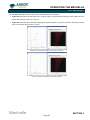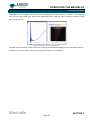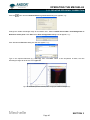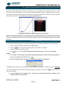
1
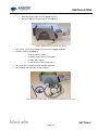
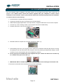
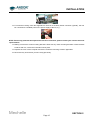
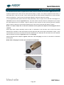
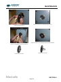
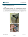
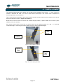
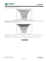
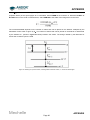
USER GUIDE Mechelle Andor Technology plc 2011 www.andor.com Version 3.1 - July 2011 TABLE OF CONTENTS PAGE SECTION 1 - INTRODUCTION TO THE ANDOR MECHELLE 7 1.1 - WORKING WITH THE USERS GUIDE 8 1.2 - DISCLAIMER 8 1.3 - TRADEMARKS & PATENT INFORMATION 8 1.4 - HELP & TECHNICAL SUPPORT Europe USA Asia-Pacific China 9 9 9 9 9 1.5 - SPECIFICATIONS 10 Mechelle TABLE OF CONTENTS Page 2 TABLE OF CONTENTS PAGE SECTION 2 - INSTALLATION 11 2.1 - UNPACKING & HANDLING 11 2.2 - OPTIONAL ACCESSORIES 13 2.3 - PCI CONTROLLER CARD INSTALLATION 14 2.4 - INSTALLING THE SOFTWARE 2.4.1 - Windows ME/XP/Vista 2.4.2 - Windows NT/2000 17 17 17 Mechelle TABLE OF CONTENTS Page 3 TABLE OF CONTENTS PAGE SECTION 3 - OPERATING THE MECHELLE 18 3.1 - LAUNCHING THE APPLICATION 18 3.2 - MECHELLE SETUP 19 3.3 - ACQUIRING DATA 24 3.4 - WAVELENGTH CALIBRATION USING MERCURY LAMP 25 3.5 - CALIBRATION 3.5.1 - Calibration Files 3.5.2 - Displaying results 26 30 31 3.6 - CROSS TALK 33 3.7 - SUB-SPECTRUM 34 3.8 - ECHELLE GRATING EFFICIENCY 36 3.9 - STANDARD LAMPS 37 3.10 - GRATING EFFICIENCY CORRECTION PROCEDURE 3.10.1 - REC example 1 3.10.2 - REC example 2 39 43 44 3.11 - RELATIVE EFFICIENCY CORRECTION 3.11.1 - Effect of ambient temperature on the relative efficiency correction 3.11.2 - Relative Efficiency Correction with sub-spectrum 45 46 46 Mechelle TABLE OF CONTENTS Page 4 TABLE OF CONTENTS PAGE SECTION 4 - MAINTENANCE 47 4.1 - ENTRANCE APERTURE/SLIT 48 4.2 - SHUTTER 50 4.3 - CAMERA ALIGNMENT 51 4.4 - SYSTEM EVACUATION 53 4.5 - PURGING 53 4.6 - CALIBRATION SOURCE 4.6.1 - Optional CC52 Collector/Collimator and Aiming Laser 54 55 Mechelle TABLE OF CONTENTS Page 5 TABLE OF CONTENTS PAGE APPENDIX 56 A1.1 - ECHELLE THEORY A1.1.1 - Grating Equation A1.1.2 - Echelle Layout 56 57 57 A1.2 - COMPONENTS A1.2.1 - Correction Lenses A1.2.2 - Echelle Grating A1.2.3 - Entrance and Exit Windows A1.2.4 - Field Corrector A1.2.5 - Prisms 58 58 58 58 58 58 A1.3 - MECHANICAL DIMENSIONS 61 A1.4 - TERMS & CONDITIONS 62 A1.5 - STANDARD WARRANTY AND WARRANTY SERVICES 63 A1.6 - THE WASTE ELECTRONIC AND ELECTRICAL EQUIPMENT REGULATIONS (WEEE) 2006 67 Mechelle TABLE OF CONTENTS Page 6 ABOUT THE MECHELLE SECTION 1 - INTRODUCTION TO THE ANDOR MECHELLE Thank you for choosing the Andor Mechelle range of spectrographs, which offer several new innovations to the spectroscopist. The Andor Mechelle spectrograph is based on the echelle grating principal and patented optical design, which gives extremely low cross-talk, equally spaced order separation and maximum resolution, compared with other spectrographs. The Mechelle range of spectrographs offer a simultaneously recorded wavelength range from UV to NIR with very high resolution and no overlapping wavelengths. The Mechelle’s patent for corrected off-axis optics enables the user to achieve maximum throughput and optimum Gaussian line shape and resolution. This translates to a wide wavelength range from the deep UV to NIR, with full spectral continuity, no gaps and no overlapping wavelengths. You get the whole spectrum in one single acquisition. The maximum wavelength range is set by the detector sensitivity and the low wavelength limit is set by the absorption of air. The spectrograph has a rugged compact design with no moving parts, enabling the Mechelle spectrograph to withstand more physical handling than other high performance spectrographs. This makes the Mechelle an ideal spectrograph for OEMs and non-lab based applications, from zero gravity experiments to operation in high temperature environments. The unit can also be evacuated for working in the deep UV. Andor have utilised many years experience in spectroscopy to deliver a software platform designed for spectroscopists. The Solis software allows direct control over spectrograph functionally. A user-friendly onscreen dashboard allows the user to acquire data, calibrate spectral displays, and manipulate post acquisition data. The speed of the system is only dependent on the integration time, readout rate of the camera and the PC capabilities. The Andor Solis software is also compatible with other spectroscopic data analysis like GRAMS/Al. The Mechelle spectrographs are integrated with CCD or ICCD detectors form Andor Technology, which enables the user to rapidly obtain accurate data. This makes the Mechelle spectrograph highly attractive to many spectroscopic applications like Laser Induced Breakdown Spectroscopy, Raman spectroscopy, Laser ablation, etc. Mechelle SECTION 1 Page 7 ABOUT THE MECHELLE 1.1 - WORKING WITH THE USERS GUIDE This manual is aimed at experienced researchers who will be using the Mechelle to analyse samples spectroscopically. Details are provided on all features and functionality. As far as possible, the descriptions in this User’s Guide are laid out in sections that mirror the Windows Interface. So, whenever you’re working with a particular window, you’ll find a section in the User’s Guide that sets that window in context, reminding you how the window is launched, letting you know what it can do, and telling you what other windows and operations are associated with it. We hope you find use of our product rewarding. If you have any suggestions as to how our software, hardware or documentation could be improved, please let us know. Contact details of your nearest Andor representatives can be obtained on the next page. 1.2 - DISCLAIMER THE INFORMATION CONTAINED HEREIN IS PROVIDED "AS IS" WITHOUT WARRANTY, CONDITION OR REPRESENTATION OF ANY KIND, EITHER EXPRESS, IMPLIED, STATUTORY OR OTHERWISE, INCLUDING BUT NOT LIMITED TO, ANY WARRANTY OF MERCHANTABILITY, NON-INFRINGEMENT OR FITNESS FOR A PARTICULAR PURPOSE. IN NO EVENT SHALL ANDOR BE LIABLE FOR ANY LOSS OR DAMAGE, WHETHER DIRECT, INDIRECT, SPECIAL, INCIDENTAL, CONSEQUENTIAL OR OTHERWISE HOWSOEVER CAUSED WHETHER ARISING IN CONTRACT TORT OR OTHERWISE, ARISING OUT OF OR IN CONNECTION WITH THE USE OF THE INFORMATION PROVIDED HEREIN. COPYRIGHT AND PROTECTIVE NOTICES 1. The copyright in this document and the associated drawings are the property of ANDOR TECHNOLOGY plc and all rights are reserved. This document and the associated drawings are issued on condition that they are not copied, reprinted or reproduced, nor their contents disclosed. 2. The publication of information in this documentation does not imply freedom from any patent or proprietary right of ANDOR TECHNOLOGY plc or any third party. 1.3 - TRADEMARKS & PATENT INFORMATION • Andor, the Andor logo and the Mechelle are trademarks of Andor Technology plc. • All other marks are property of their owners. • Changes are periodically made to the product and these will be incorporated into new additions of the manual. Mechelle SECTION 1 Page 8 ABOUT THE MECHELLE 1.4 - HELP & TECHNICAL SUPPORT If you have any questions regarding the use of the Mechelle, please contact the representative* from whom your system was purchased, or: Europe USA Andor Technology Andor Technology 7 Millennium Way 425 Sullivan Avenue Springvale Business Park Suite # 3 Belfast South Windsor BT12 7AL CT 06074 Northern Ireland USA Tel. +44 (0) 28 9023 7126 Tel. (860) 290-9211 Fax. +44 (0) 28 9031 0792 Fax. (860) 290-9566 www.andor.com/contact_us/support_request www.andor.com/contact_us/support_request Asia-Pacific China Andor Technology (Japan) Andor Technology 7F Ichibancho Central Building Room 502 22-1 Ichiban-Cho Yu Yang Zhi Ye Building Chiyoda-Ku A2 Xiao Guan Bei Tokyo 102-0082 Chaoyang District Japan Beijing 100029 Tel. +81 3 3511 0659 China Fax. +81 3 35110662 Tel. +86-10-5129-4977 Fax. +86-10-6445-5401 www.andor.com/contact_us/support_request www.andor.com/contact_us/support_request *NOTE: THE CONTACT DETAILS FOR YOUR NEAREST REPRESENTATIVE CAN BE FOUND ON OUR WEBSITE. Mechelle SECTION 1 Page 9 ABOUT THE MECHELLE 1.5 - SPECIFICATIONS ME5000 / iStar DH734 Wavelength range* Focal length Aperture Spectral resolution (λ/Δλ) FWHM Dispersion Channel height Channel width Minimum distance between orders Maximum distance between orders Number of channels in range Horizontal magnification Vertical magnification Stray light Optical axis Shutter rate Length Width Height Weight ME5000 / DV434 200 - 975 nm with spectral continuity, no gaps 195 mm F#7 4000 (4 pixels FWHM) 5000 (3 pixels FWHM) λ/16400/channel 5 pixels, 3 pixels, 1 pixel, switch selectable 1 pixel 9 14 25500 0.81 1.66 -4 1.5x10 measured at 20 nm from 633 nm laser line 152.4 mm (6.4”) with feet 1 Hz (optional) Dimensions & Weight 350 mm (13.8”) without camera 100 mm (3.94”) without feet 200 mm (8.66”) without feet 10 kg (22Ib) NOTE*: This is the Mechelle wavelength range and if a shorter spectral range detector is used, this range will be reduced. For example, if an iStar DH734-18F-03 was used (spectral range = 180 - 850 nm), the overall wavelength would be 200 - 850 nm. Mechelle SECTION 1 Page 10 INSTALLATION SECTION 2 - INSTALLATION 2.1 - UNPACKING & HANDLING BEFORE unpacking the instrument, allow the shipping box to acclimatise to room temperature. This is to avoid condensation forming on the Mechelle. 1. Always use the handles to carry the Spectrograph, i.e.: Figure 2: Incorrect handling Figure 1: Correct Mechelle handling technique 2. Although the Mechelle requires no special placement in a controlled environment, it should be noted that it is a precision instrument that will perform best when set up and operated properly. Please read this manual carefully before use and always handle with the care accorded to any precision instrument. Mechelle SECTION 2 Page 11 INSTALLATION Carefully remove the Mechelle from its packaging. The following items should be included: • Mechelle spectrograph unit (see figure 3 below) • CCD or ICCD camera (pre-aligned, see figure 3) Figure 3: Mechelle fitted with an Andor iStar camera • PCI card for connecting the detector to the PC (see figure 4 below) • Interface cables (see figure 4): 1x TP 04 Detector Cable 1x Shutter/Temperature Control cable 2x SMB - BNC Cables 1x Gate Monitor Cable (ICCD ONLY) • CD containing the Andor Mechelle interface software. • User Manual and Certificate of Conformance Figure 4: PCI card, Interface cables, CD & Users Manual/Certificate of Conformance Mechelle SECTION 2 Page 12 INSTALLATION 2.2 - OPTIONAL ACCESSORIES The following accessories are available for use with the Mechelle spectrograph: CC52 Collector/Collimator Aiming Laser Power Supply Please refer to page 55 for further information on the Please refer to page 55 for further information on the CC52 CC52 NOTE: These accessories are not provided as standard with the Mechelle spectrograph and must be ordered separately. Please contact us to discuss your requirements. Mechelle SECTION 2 Page 13 INSTALLATION 2.3 - PCI CONTROLLER CARD INSTALLATION The PCI Controller Card is installed in the same manner as you would fit most other slot-in cards such as graphics cards. NOTE: Please consult the manual supplied with your computer to ensure correct installation of the controller card for your particular model. We recommend you perform the installation in a similar manner to the following: 1. Power down the computer and any accessories. 2. Unplug the computer and any accessories from the wall outlet(s). 3. Whilst observing appropriate static control procedures, unplug all cables from the rear of the computer. 4. Unscrew any cover mounting screws on the computer and set them aside safely. 5. Carefully remove the cover of the computer, e.g.: 6. Situated inside the computer are a number of Expansion Slots, e.g.: 7. After deciding which slot you are going to use, remove any metal filler bracket(s) that may be covering the opening for the slot at the back of the computer. Place any retaining screw(s) and/or clip(s) in a safe container, as you will need them later in the installation procedure. 8. At this point, put on the ESD wrist strap supplied with your camera and attach the crocodile clip to a suitable earth point on the PC e.g.: 9. IMPORTANT NOTE: The ESD strap must be worn at all times when handling the Controller Card. 10. Remove the Controller Card carefully from its protective packaging Mechelle SECTION 2 Page 14 INSTALLATION 11. Firmly press the connector into the chosen expansion slot, e.g.: 12. For maximum cooling, when the supplied PCI card has an Auxiliary Power connector (“flylead”), this can be connected to a suitable point on the power supply of the PC, e.g.: NOTE: Should any problems be experienced with this connection, please contact your nearest technical representative. 13. Making sure that the card’s mounting bracket is flush with any other mounting brackets or filler brackets to either side of it, secure the Controller Card in place. 14. Replace the cover of the computer and secure it with the mounting screws if applicable. 15. Reconnect any accessories you were using previously. Mechelle SECTION 2 Page 15 INSTALLATION 1. Connect the Interface cable between the camera & the installed PCI card as shown below in figures 5 & 7 below. Also, if a shutter is provided, connect the shutter/temperature cable between the shutter housing and the PCI card as shown in figures 6 & 7 below. Figure 5: Connecting Interface cable to camera (please note warning on label) Figure 6: Shutter/Temperature cable connected to Mechelle Figure 7: PCI card connections (left = Shutter/Temperature cable, right = Interface ) 2. Switch on the computer to start the software installation Mechelle SECTION 2 Page 16 INSTALLATION 2.4 - INSTALLING THE SOFTWARE 2.4.1 - Windows ME/XP/Vista 1. During the start up sequence the operating system will detect the Andor PCI controller card and a dialogue box will prompt you for the location of the Windows ME/XP/Vista device driver. 2. Insert the Andor CD and navigate from the dialogue box to the drive containing the Andor CD. Click OK. 3. The Installation Wizard now starts. If it does not start automatically, run the setup.exe file from the CD. Follow the on-screen prompts. 4. Restart the computer to complete the installation. 2.4.2 - Windows NT/2000 NOTE: For NT computers that use Windows NT but are not actually networked, you will need administrator privileges to install the software & driver. 1. Insert the Andor CD, then using NT Explorer to navigate the Andor CD, run the install.bat program. 2. Follow the on-screen prompts until you are asked to restart the system, when you should enter No. 3. Since the Windows NT/2000 operating system is not fully Plug and Play aware, you must install the driver manually. 4. Restart the computer. Mechelle SECTION 2 Page 17 OPERATING THE MECHELLE SECTION 3 - OPERATING THE MECHELLE 3.1 - LAUNCHING THE APPLICATION The Mechelle is controlled via either the Andor Solis or iStar software and the software is launched by clicking on the Andor Solis or iStar icon; which was created when the software was installed. The Andor Solis Splash Screen then appears briefly, e.g.: The Main Window then appears, e.g.: Mechelle SECTION 3 Page 18 OPERATING THE MECHELLE 3.2 - MECHELLE SETUP From the Main Window, select Hardware, Setup Spectrograph, e.g.: The Setup Spectrograph dialog box appears, e.g.: Select Andor from the Manufacturer dropdown menu and Mechelle as the Spectrograph. The Setup Mechelle tab should then appear. Click this tab and the Mechelle Setup dialog box will appear, e.g.: Then required parameters can then be selected. Mechelle SECTION 3 Page 19 OPERATING THE MECHELLE Alternatively (again from the Main Window), the Calibrate, X-Calibration by Spectrograph option can be selected e.g.: In this instance, the Spectrograph X-Calibration for Acquisition dialog box appears, e.g.: Click on the Setup Spectrograph tab and the Setup Spectrograph dialog box appears. Again, the procedure shown on the previous page is used to set up the Mechelle. Mechelle SECTION 3 Page 20 OPERATING THE MECHELLE In the XML Setup File field of the Mechelle Setup dialog box, click on the button, then locate and select the appropriate .xml file for the Mechelle model being used, , e.g.: Click the Open button. The following warning message will appear: NOTE: Click OK, but do not restart at this point during the setup procedure, as the configuration file will be saved later. The Mechelle Setup screen will then appear again, e.g.: Mechelle SECTION 3 Page 21 OPERATING THE MECHELLE The Calibration Temp window indicates the Prism temperature during calibration and the Current Temp window indicates the actual prism temperature. NOTE: The extract spectrum from acquisitions option must be selected if the user wishes the spectrum to be generated or updated following every acquisition. • The Automatic Peak Finder option defines the pixel search area tolerance used to locate the maximum signal point on a spectrum. • The Enable Element Labels option allows the user to display the actual element on a spectrum display as per the example image on page 32. • The Draw Order Lines on Image option has the effect of superimposing lines over the image, relating to where the software has calculated the Orders to be located. NOTE: After the application is restarted, the draw order lines on image button will also be shown on the right side of the main window toolbar. This button also toggles this option ON and OFF. Close all dialogue boxes, then save as shown: The file can then be saved, e.g.: NOTE: The configuration file must be named either istar.cfg or AndorSolis.cfg. After the Save button is pressed, the following message will appear : Click Yes and the following prompt will appear : Click OK. THE APPLICATION MUST THEN BE RESTARTED BEFORE THE MECHELLE SYSTEM CAN BE USED. Mechelle SECTION 3 Page 22 OPERATING THE MECHELLE After the system is restarted, the Solis splash screen will appear followed by the Main Window again. On the Main Window, click the button and the Setup acquisition dialog box will appear e.g.: Select the required parameters then click OK. NOTES: 1. The exposure time setting in the Setup CCD section must be greater than the gate pulse width setting (in the Setup Gater section). Enter the other required parameters as needed to run the camera (for more detail, please refer to the camera user manual). 2. The Step ‘n’ Glue tab is displayed, but the function is disabled on the Mechelle, e.g.: Mechelle SECTION 3 Page 23 OPERATING THE MECHELLE 3.3 - ACQUIRING DATA To acquire your first data, click the button on the Main Window. The configuration file (.cfg) that comes with the Andor software enables the system to make an acquisition using a number of default conditions including Single scan Acquisition Mode with Image Frame Readout and 1 second Exposure Time. The acquired data will appear in Data Windows #0 and #1, as shown in the example (figure 8) below. #0 will show the raw data as an image and #1 will show the extracted spectrum from #0. NOTE: The CCD should also be cooled at this point. The camera user guide provides full details of how data can be acquired and manipulated. Figure 8: Acquired data NOTE: For further information on how to zoom, please consult the user’s guide for the camera you are using. Mechelle SECTION 3 Page 24 OPERATING THE MECHELLE 3.4 - WAVELENGTH CALIBRATION USING MERCURY LAMP The Mechelle Spectrograph and camera are pre-aligned and calibrated at the factory. The Mechelle must be re-calibrated if any of the following occurs: • The ambient temperature changes more than ±5°C from calibrated temperature • The fiber is changed • The Entrance Slit is changed to a fiber or vice versa • The camera is moved or re-aligned • The shutter housing is removed • The Mechelle is evacuated To do this you should switch on a known source (a Mercury/Argon lamp is recommended) and take a signal. NOTE: If the Mechelle has a slit option, make sure that the Mercury lamp is set at 50cm from slit and filling the F# of the Mechelle. Look at the image of 253.652 nm line in #0, which should appear near the middle of the detector (X ≈ 500, Y ≈ 300 for Mechelle 5000) and should look similar to figure 9 below: Figure 9: Captured data from an Hg calibration source If the Mechelle has a fiber option, connect the fiber-to-fiber connector and place the other end near the mercury lamp. NOTE: Make sure that detector is not saturated. If the detector is saturated, reduce the exposure time, gate pulse width or gain. Mechelle SECTION 3 Page 25 OPERATING THE MECHELLE 3.5 - CALIBRATION Click the button on the main window and the Select Calibration File dialog box will appear, e.g.: Set the Calibration file & Search window size, e.g.: NOTE: It is recommended to start the calibration procedure with 1 line calibration followed by 6 line calibration. The Search window size option defines the area of a square of pixels with sides equal to the selected number. The square is the area surrounding each calibration line, the position of which is determined in the wavelength calibration. Based on the previous calibration, the program will look for each calibration line within the defined search area. If too low a number is selected, the calibration procedure may not find some of the calibration lines. Too large a number increases the risk of locating the wrong line. If a reasonably good calibration exists, a suitable selection for this parameter is from 20 to 50. Mechelle SECTION 3 Page 26 OPERATING THE MECHELLE When the calibration button is pressed, the Results of Mechelle calibration screen appears (figure 10 below). The success of the calibration can be judged from this information. Figure 10: Calibration results screen (1x line) The following error message can sometimes appear: This can be caused by either one of the following problems: 1. Search window size is too small. 2. Spectral lines are very weak. To compensate, increase exposure time, gain or gain pulse width. Mechelle SECTION 3 Page 27 OPERATING THE MECHELLE The Found Lines table (see figure 10 on the previous page and figure 11 below), contains the calibration wavelengths and their order numbers. The third column represents the intensity of this line in counts. The table on the right-hand side, entitled Line Details, shows initial, measured and calculated positions of the lines. All co-ordinates are in units of the pixel size. The initial position of the lines as calculated from the “old” set of wavelength calibration constants, i.e. calculated from previous calibration. The second row contains the measured pixel co-ordinates and the third row contains the pixel co-ordinates calculated from the “new” (not yet stored) wavelength calibration constants. The fourth row contains the residuals, i.e. the difference between the calculated and measured co-ordinates. The fifth row shows the full width half maximums calculated for each of the lines. The residuals, both in the horizontal (X) and vertical (Y) directions, are plotted in a diagram. The size of the plotted area equals the size of the search window. If one line calibration file is used, the residuals (in X and Y direction) equal zero. The optimum wavelength calibration is performed if the selected “calibration wavelength file” contains several (≥5) lines, as shown, e.g.: Figure 11: Calibration results screen (6x lines) Mechelle SECTION 3 Page 28 OPERATING THE MECHELLE A good calibration based on several lines should have a maximum residual of less than one pixel in the x and y directions for lines within the echellogram funnel. Lines outside the funnel are used for extra calibration accuracy, but the spectrum is only extracted from within the funnel; due to optical aberrations away from the horizontal centre, lines outside the funnel may have residuals slightly greater than 1 pixel. If the red dot moves away from the centre of the cross-hairs when the Found Lines are tabbed down, the calibration is unsuccessful and must be cancelled. This plot is the graphical representation of the Residuals values from the Line Details section. The calibration is accepted by pressing the Use Calibration Result (Save) button. If residuals are bigger than Residuals Maximum, the software will not allow the same calibration. After the “new” constants have been saved, all subsequent measurements will be based on these. It is advisable to perform a one-line calibration first, as described above using a large search window, then use several line calibration file and restrict the search window to 10 - 20 pixels. This will ensure that the optimum calibration will not identify the wrong line. Also make sure none of the lines saturate the detector. NOTE: To use a large number of calibration lines (>12 lines), select Accumulate on the Acquisition mode drop-down on the Setup Acquisition dialog box (see figure 12 below) to improve signal to noise ratio. This will ensure that the calibration procedure will find all lines. Figure 12: Accumulate setting Mechelle SECTION 3 Page 29 OPERATING THE MECHELLE 3.5.1 - Calibration Files There are a number of calibration files in the list. Each file contains the calibration line information for wavelength calibration. This file can be prepared using any editor. An example of such a Wavelength Calibration file is shown here: The first line of the file contains a number of calibration lines. Each line entry contains the spectral order of the line and its wavelength in µm given with an accuracy of at least 6 decimal places. Items are comma-separated. The spectral order can be calculated as follows: Spectral order = Order wavelength constant / wavelength (µm) The table below shows the Order wavelength constant for each Mechelle model: Mechelle model / Camera model ME 5000 / DV434 ME 5000 / DH734 ME 5000/DV434 Order Wavelength Constant 20.139 20.139 20 139 NOTE: The .xml file also contains this information. Use the nearest integer of the calculation quotient as the spectral order number. If the quotient is close to half way between two orders (e.g. 75.38) the same line can be entered in two spectral orders, namely order 75 and 76. In such a case the line should be entered as two separate entries in the calibration file. Mechelle SECTION 3 Page 30 OPERATING THE MECHELLE 3.5.2 - Displaying results After the unit has been calibrated and the image has been captured, the results can be displayed according to the preference of the user. From the Main Window, select Display and choose Display preferences. The Display preferences dialog box will be displayed, e.g.: The user can then select the format required. Individual elements can also be filtered using a Periodic Table selector. This is initiated by clicking the button on the Main Window. The Periodic Table of Elements dialog box will be displayed as per figure 13 below. The user can then select the parameters required to identify the relevant element from this screen. Figure 13: Periodic Table of Elements dialog box Mechelle SECTION 3 Page 31 OPERATING THE MECHELLE The results of the Display preference and/or Periodic table selections are displayed on the Main Window, e.g.: When the cursor is moved to a point on the spectrum window, the cursor on the image moves to the corresponding line e.g.: Mechelle SECTION 3 Page 32 OPERATING THE MECHELLE 3.6 - CROSS TALK Cross talk is the light from one order crossing to the adjacent order (or orders) and shows as an extra line on the spectrum. Cross-talk amplitude depends on many parameters: 1. Distance between orders: Larger distance results in smaller cross talk. This distance depends on the optical design of the Mechelle and cannot be changed. The Mechelle has a large distance between orders because of the patent dual prism design. 2. Channel height: It is software controlled and cross talk is proportional to the channel height, remember when channel height is reduced the amplitude of signal will also be reduced. 3. Slit height of fiber diameter: Cross-talk also increases with slit height (or fiber diameter). There is no standard definition to cross talk and all Echelle based spectrograph manufactures (except Andor) do not specify the cross talk. See Andor spec sheet for definition and specification of your Mechelle model. To set up the number of orders to be removed, open the Mechelle Setup screen (as shown on page 21) then select the required number from the Crosstalk Removal Order dropdown menu e.g.: To remove cross-talk lines, click the button. NOTES: 1. This function removes up to three orders. For example, if large (> 50μm) fiber is used, more than one cross talk will be seen. Also if the CCD over saturate and smear then more than three orders will be seen. Never saturate the CCD. 2. When cross talk is removed, the software will show a zero value to indicate that cross talk lines have been removed. Mechelle SECTION 3 Page 33 OPERATING THE MECHELLE 3.7 - SUB-SPECTRUM To see a full spectrum, a full image (1024 x 1024 pixels) must be read out which could take more than one second. In order to speed up number of spectrum per second, a sub-Spectrum is used. Click the button and the Wavelength Select screen will appear with the Wavelength Range option, e.g.: Select Sub Spectrum. The Wavelength Select dialog box will then appear, e.g.: The slider shown above can then be used to select the required wavelength. The slider has three labels floating above it displaying the start, centre and end wavelengths currently in effect. The values displayed correspond to the position and width of the slide bar in relation to the wavelength scale shown. The start, centre and end wavelengths can be changed in one of two ways: 1. By dragging the slider with the mouse. This is done by positioning the cursor within the slider (cursor changes to pointing hand), holding down the LEFT mouse button and dragging the slider to the new centre wavelength required. Placing the cursor at either side of the slider allows you to nudge it towards the cursor (use the LEFT mouse button for coarse nudges and the RIGHT mouse button for fine nudges). The size of the nudges can be defined by the user but the defaults are 10 nm for coarse nudges and 1 nm for fine nudges. 2. By using the Wavelength Control dialog box shown below. This is accessed by positioning the cursor on the wavelength value on the slider then clicking the LEFT mouse button. The dialog box then appears, e.g.: Type in the required wavelength then click Ok Mechelle SECTION 3 Page 34 OPERATING THE MECHELLE The sub-image area required is calculated by the software and displayed in the image window (#0) (figure 14 below). Only the sub-image is then read out and a sub-spectrum is extracted from it. NOTE: In Full Spectrum mode, the software automatically calculates the background subtracted from spectrum. In Sub-spectrum mode, the software does not calculate the background therefore a background corrected is used. Figure 14: Sub-image area Mechelle SECTION 3 Page 35 OPERATING THE MECHELLE 3.8 - ECHELLE GRATING EFFICIENCY Echelle gratings produce a series of different orders over the entire spectral range of interest (e.g. the ME5000 model produce 80 orders). When the grating is used in the Littrow angle, the grating efficiency at its maximum in the middle of each order. However the efficiency drops to about half of this value at the extremities of each order. An Echelle grating is blazed for all wavelengths in a spectral range for a given diffraction order. Figure 15: Echelle grating efficiencies The effect of the grating efficiency can be clearly observed when a Continuous Wave (CW) light source is used. Figure 16 below shows a typical spectrum of deuterium CW light source. Echelle grating efficiency can be corrected with the aid of Standard lamps (also known as “black body” lamps) and software logarithm. Figure 16: Deuterium CW light source spectrum Mechelle SECTION 3 Page 36 OPERATING THE MECHELLE 3.9 - STANDARD LAMPS Operating and maintaining black body sources is a difficult and skilled task and is usually only done by national standards labs such as the National Institute of Standards and Technology (NIST) in the USA (formerly known as NBS). A more practical calibration source is a CW incandescent tungsten filament lamp that has been calibrated against a black body source. These filament lamps are known as primary working standard lamps; some are of particularly elaborate design with special filaments and stress free envelopes, but all give good uniform illumination and are operated from well regulated power units. These primary working standards remain at NIST, but NIST will supply a secondary working standard and its power unit, calibrated from the primary working standard, or they will calibrate a lamp and power unit supplied by you (National labs in other countries offer similar services). Also there are some commercial companies sales these standard lamps. The lamps are supplied with calibration data consisting of a printed list of Irradiance outputs at different wavelengths at a specified distance from the lamp. These secondary standards are expensive and have short life times (about 200 hours). General purpose filament lamps, graded for good uniformity, are more commonly used as standards; these have been calibrated against a secondary standard and give traceable accuracies of 5% to 10%. Since the Mechelle has a very wide wavelength range, the standard lamp used must cover the same wavelength range or more. Unfortunately these is no lamp can cover 200nm - 975nm, therefore two lamps are required to carry out this procedure. Typically a deuterium lamp is used from 200 - 400nm then a Quartz Tungsten Halogen (QTH) lamp is used to from 380 - 975nm. Deuterium lamps are arc lamps filled with deuterium at low pressure. They produce high, spectrally smooth, UV output with little visible and IR, this makes them ideal as UV spectral irradiance standards. For reasons we will not go into here, accuracy and reproducibility in this wavelength range is about half that attainable in the visible range. Mechelle SECTION 3 Page 37 OPERATING THE MECHELLE Figure 17: Spectral irradiance output of a deuterium standard lamp and QTH Many commercial companies supply both QTH and deuterium standard lamps with regulated power units, and cover the wavelength range of 200 nm - 1100 nm. Figure 17 above shows a typical output of a standard lamp. Before commencing grating efficiency correction the following criteria must be met: 1. The standard calibration data relating to your particular standard lamps are saved in text files (*.txt) in specified directory. These files will most likely have been supplied by your lamp vendor. Each line of the -2 -1 file contains a wavelength (in nm) and an irradiance value (µW cm nm ) separated by one or more spaces or tabs. If a file is not supplied with your lamp, you may use a text editor to create one of your own from the lamp vendor’s data sheet. NOTE: The two files must have at least 50nm overlap. 2. Full-spectrum mode is selected 3. Accurate wavelength calibration is carried out 4. Select setup acquisition mode to either “single scan” or “Accumulate” Refer to detector specification to find the detector spectral range. e.g. iStar 18F-03 spectral range (180 - 850 nm). Mechelle SECTION 3 Page 38 OPERATING THE MECHELLE 3.10 - GRATING EFFICIENCY CORRECTION PROCEDURE To correct for grating efficiency, either click the button or select Acquisition, Setup date type from the drop-down menu, select Counts (R.E.C.) then click on the Do correction button. NOTE: R.E.C. stands for Relative Efficiency Correction. The Relative Efficiency Correction dialog box will appear, e.g.: • Select useable wavelength range, this is a combination of spectrograph range and Detector spectral range, e.g. if an Detector iStar 18F-03 is used (spectral range 180 - 850 nm) with an ME5000 (wavelength range 200 - 975 nm). The minimum wavelength will be determined by the ME5000 (200 nm) and the maximum wavelength will be determined by the detector (850 nm), therefore the usable wavelength range will be 200 - 850 nm. • Select wavelength overlap between the two calibrated light sources, e.g. if a deuterium lamp/QTH lamp are used, the overlap is 390 nm. • Select the appropriate standard calibration data file. Mechelle SECTION 3 Page 39 OPERATING THE MECHELLE Switch off the light source and then click Take Background: Switch on calibrated light source 1 and wait for it to stabilise (refer to the light source manual for the waiting time). NOTE: Source 1 is the source with the shorter wavelength range (e.g. deuterium) Click Take Reference 1: Switch off source 1, switch on source 2 and wait for it to stabilise. Click Take Reference 2: Your calibration is now complete. It is recommended to save the configuration file, so you don’t have to repeat this calibration again if you switch off the PC. On the Save Configuration dialog box, click Yes: Select same configuration file name (istar.cfg for the iStar detector or AndorSolis.cfg for CCD), then click Save, e.g.: Replace the existing configuration file by clicking on Yes, e.g.: The new configuration file is now saved. Click OK: Mechelle SECTION 3 Page 40 OPERATING THE MECHELLE The relative efficiency correction is now complete and the system ready for use. NOTE: Window #1 contains the following five tabs (shown in figure 18 below): 1. Source: the data taken from the standard lamp (see figure 23 on page 42). 2. Ref: the data recorded when the standard lamp is switched on minus the background scans. See figure 21 on page 42). 3. Cf: the correction factor calculated for source data and Ref data (see figure 20 below). 4. Live: the row data of a new signal. An example for a QTH lamp is shown in figure 22 on page 43). 5. Sig: the new data after applying the correction factor Cf. An example is shown in figure 19 below. Figure 18: Tabs Figure 19: Sig tab = Signal after correction Figure 20: Cf tab = Correction factor Mechelle SECTION 3 Page 41 OPERATING THE MECHELLE Figure 21: Ref tab = signal from a deuterium (200 - 390nm) lamp and QTH lamp (390 - 800nm) Figure 22: Live tab = row data from QTH lamp before correction Figure 23: Source tab = combined source data from a deuterium lamp (200 - 390 nm) and a QTH lamp (390 - 800 nm) Mechelle SECTION 3 Page 42 OPERATING THE MECHELLE 3.10.1 - REC example 1 The following example shows the effect of the relative efficiency correction. • Figure 24 shows the row data (live) from a mercury lamp, if shows that the intensity of the 546nm line has double the intensity of the 253.7 nm line • Figure 25 shows the same data after applying the relative efficiency correction. Here the intensity of 546nm line is much lower than the 253.7 nm line Figure 24: Live signal from a Mercury lamp before correction Figure 25: Signal from the Mercury lamp after correction Mechelle SECTION 3 Page 43 OPERATING THE MECHELLE 3.10.2 - REC example 2 Figure 26 shows the signal from a QTH lamp after applying the relative efficiency correction. It is clear that there are very large noise levels at the lower wavelengths (200 - 350 nm). This is caused by a lack of signal from the light source. Figure 26: Signal from QTH lamp after correction This part of the wavelength can be removed by changing the useable wavelength range in the relative efficiency correction. This can be done by following the procedure shown on the next page. Mechelle SECTION 3 Page 44 OPERATING THE MECHELLE 3.11 - RELATIVE EFFICIENCY CORRECTION Click the button and the Relative Efficiency Correction dialog box appears, e.g.: Change the usable wavelength range to be between 350 - 800nm. NOTE: Do not take a new Background or Reference at this point. Click Ok and the Save Configuration dialog box will appear, e.g.: Click Yes and the Save As dialog box will then appear, e.g.: Type in the required filename (e.g. istar.cfg), then click Save. When a new acquisition is taken, the new wavelength range will be shown as in figure 27: Figure 27: Corrected signal from QTH lamp after changing the usable wavelength range Mechelle SECTION 3 Page 45 OPERATING THE MECHELLE 3.11.1 - Effect of ambient temperature on the relative efficiency correction When the ambient temperature changes, the refractive index of the prisms will change which result in a shift of the orders in the vertical direction, i.e. the light of a certain wavelength will fall on a different pixel on the CCD. Since there is a small variation between the response of CCD pixels, therefore the relative efficiency correction will not be valid and the corrected signal should look like figure 28 below: Figure 28: Effect of the temperature change on relative efficiency corrected signal NOTE: If the ambient temperature is changed by ±3ºC, the Relative Efficiency Correction will not be valid and the corrected signal will look similar to figure 28 above, but the wavelength calibration will remain accurate. 3.11.2 - Relative Efficiency Correction with sub-spectrum To carry out the relative efficiency correction with sub-spectrum, the following procedure must be carried out: 1. Firstly, take a full spectrum as described on pages 23 -24. 2. Click the button to select the wavelength range required and click update 3. Close the wavelength selector window 4. Click and carry out the Relative Efficiency Correction Procedure as described on page 45 NOTES: 1. Do not take a scan between selecting the wavelength range and relative efficiency procedure. if you do, the button will not be active, i.e. 2. If the wavelength range is changed, the following message will be displayed: The REC procedure must then be repeated. The software will also change the acquisition settings to Full Image for the next acquisition only to prepare for Relative Efficiency procedure. Just click the button and carry out the procedure again. 3. If the sub-spectrum set is between 400 - 975 nm, only a QTH Standard lamp is needed, so the deuterium lamp is not necessary. Mechelle SECTION 3 Page 46 MAINTENANCE SECTION 4 - MAINTENANCE DO NOT TRY TO OPEN THE MECHELLE SPECTROGRAPH. IF YOU OPEN IT, THE WARRANTY WILL BE VOID. Maintenance of the Mechelle spectrograph is minimal. There are no user-serviceable parts inside the spectrograph. The optics in the Mechelle spectrograph are factory adjusted before delivery. Inside the Mechelle spectrograph there are sensitive parts that must be handled by authorised personnel only. Please observe the following general precautions: • When the Mechelle is not being used, it is recommended to protect the fiber optic input connection with the protection cap, included in the delivery • Never use aggressive cleaning substances, e.g. benzene, spirit, nitro solvents, etc. commonly found in labs. Such substances may destroy or damage the surface on which they are applied • During use, the Mechelle should be protected from hard shocks or strong vibrations • The Mechelle should be protected from high humidity levels and temperature changes • It is important not to scratch the surface of the fiber ends, as this significantly will reduce the light input. It is therefore recommended to always keep the protection cap on each end of the fiber when it is not in use. The fiber itself should be cleaned only by dry dust free air or adequate fluids for optical surfaces Mechelle SECTION 4 Page 47 MAINTENANCE 4.1 - ENTRANCE APERTURE/SLIT The standard Mechelle 5000 is supplied with the SMA connector & brass tool as shown in figure 27 below. The maximum aperture size, which can be used with this design, is 50μm. The entrance aperture can be either, a direct fiber input, a slit or a pin hole. When a fiber-optic input is used, the best arrangement is to have the fiber itself as the aperture. This must not exceed 50μm diameter, otherwise orders will overlap. In some applications fiber-optics cannot be used, particularly in the UV region, due to the lack of throughput, so a Slit Disc must be used (see figure 28 below). The most common slit size used is a rectangular 25 μm x 50μm slit. Other apertures such as a 50μm x 50μm or 50μm pin hole can also be used, but they give less resolution than the 25μm x 50μm slit. The maximum aperture size, which can be used with this design, is 50μm. NOTE: If a 10μm x 50μm slit is used the resolution of the system will improve but throughput will be reduced. When larger fiber (>50μm diameter) must be used, a combination of slit and fiber can be used. The slit will determine the resolution of the spectrograph and the large fiber will ensure higher transmission of light. In this case the SMA connector is removed, the slit disk is attached to the Mechelle then the SMA connector attached after the slit disk as shown in figures 29 - 32 on the next page. Optional ST & FC fiber adapters (figures 33 & 34 on the next page) can also be used with the Mechelle spectrograph. NOTE: After changing slit to fiber, the unit must be recalibrated. Figure 27: SMA connector & brass insertion tool Figure 28: Slit disc & brass insertion tool Mechelle SECTION 4 Page 48 MAINTENANCE Figure 30: Shutter housing fitted with Slit Disc only Figure 29: Inserting Slit Disc Figure 32: Shutter housing fitted with SMA connector & Slit Disc Figure 31: Fitting SMA connector over Slit Disc Figure 34: ST connector Figure 33: FC connector Mechelle SECTION 4 Page 49 MAINTENANCE 4.2 - SHUTTER The Shutter is an optional item on the Mechelle system. • If an ICCD is used, the image intensifier is used as a shutter. • If a CCD is used, a shutter must also be used to ensure that no light falls on the CCD during the readout. The shutter is located behind the slit in the shutter housing. The shutter housing contains an electronic shutter driver which is controlled, by the Andor PCI card, through a Shutter/Temperature cable. To improve the throughput of the system (especially in the UV region) the shutter housing can be flushed with dry gas to remove any water vapour. This can be done via the two access holes (normally sealed by grub screws) which are located at the top and bottom of the shutter housing, as shown in figure 35 below. The slit can also be adjusted using an Allen Key as shown in figure 36. Figure 35: Shutter housing & flushing ports Figure 36: Adjusting slit Mechelle SECTION 4 Page 50 MAINTENANCE 4.3 - CAMERA ALIGNMENT The Mechelle Spectrograph and camera are pre-aligned and calibrated at the factory. In some cases, the camera is detached and used on its own or with another spectrograph. The camera must be aligned and focused again when it is put back on. This is carried out by loosening the three grub screws & the Allen screw located on the top, bottom & one side of the camera flange as shown in figures 37 & 38 below. Rotate and focus the camera to achieve the smallest image possible (3 pixels FWHM in CCD and 5 pixels FWHM in ICCD in x-direction. Also ensure that the 253 nm line from Hg source falls near the following pixels (X = 500, Y = 300) with ±10 pixels margin. The three grub screws & Allen screw can then be tightened again. Camera Alignment Grub Screws Flushing Port Grub Screw Figure 37: Camera flange (left aspect) Camera Alignment Grub Screw Camera Alignment Allen Screw Figure 38: Camera flange (right aspect) Mechelle SECTION 4 Page 51 MAINTENANCE To check the alignment, use a CW source and re-calibrate. The halo on the image as shown on this example should be as near to horizontal as possible: To focus the camera, move it fractionally forward/backwards. The image as shown in below should be as small as possible. This image is also used to align the slit Mechelle SECTION 4 Page 52 MAINTENANCE 4.4 - SYSTEM EVACUATION All Mechelle models are filled with dry Nitrogen and sealed. In some Mechelle models an optional vacuum valve is attached so that the spectrograph can be evacuated, e.g.: Figure 39: Optional Vacuum Valve The Mechelle spectrograph is pumped to 1 x 10 -3 mbar at the factory. It is recommended to pump out the Mechelle once a year to help maintain the best throughput performance, especially in the UV region. To pump the Mechelle, carry out the following procedures: 1. Connect vacuum valve to vacuum pump and start the pump 2. Wait for one minute then turn vacuum valve counter-clockwise to open 3. Pump the Mechelle for 30 minutes and then close the valve. It is important to open the valve after the pump is turned on and to close the valve before the pump is turned off to avoid the destruction of the vacuum or the unwanted backflow of pump oil into the Mechelle. NOTE: You must recalibrate the Mechelle each time after pumping. 4.5 - PURGING A pocket of air becomes trapped between the camera and the spectrograph, which may reduce the throughput of the spectrograph. This can be flushed out with dry gas to remove the water vapour. Flushing is done via the two ports (1x each side of the camera flange, normally sealed by grub screws) which are shown on figures 37 & 38 on page 51. Mechelle SECTION 4 Page 53 MAINTENANCE 4.6 - CALIBRATION SOURCE To wavelength calibrate the Mechelle spectrograph a spectral calibration source is needed. A Mercury/Argon lamp is recommended for Mechelle calibration. 184.950 nm Hg I wavelengths 253.652 nm 302.150 nm 404.656 nm 296.728 nm 302.347 nm 407.783 nm 313.155 nm 433.922 nm 313.184 nm 434.749 nm 334.148 nm 435.833 nm 365.015 nm 491.607 nm 365.484 nm Mechelle 546.074 nm 576.960 nm 579.066 nm SECTION 4 Page 54 MAINTENANCE 4.6.1 - Optional CC52 Collector/Collimator and Aiming Laser To match the performance of modern broadband spectrographs, a unique patented UV-NIR achromatic collecting/collimating lens/mirror system, the CC52, has been designed (see figure 40 below). It is optimised to ensure that all wavelengths in the range 200 - 1100 nm are collected evenly into the entrance fiber for use with any type of spectrograph. Figure 40: CC52 Collector/Collimator CC52 Specification f/number Focal Length Aperture Object Distance Wavelength Range Fiber Optics Connector Items Included 2 mm 52 mm 30 mm 200 mm to Infinity 200 - 1100nm Standard SMA Aiming laser (5 mW) and 3V adapter To complement the CC52, there is a very useful alignment laser (figure 41 below). This allows optimisation of the input optics between the application and the spectrograph. By coupling a laser beam through the optical fiber from the spectrograph end, the CC52 can be set and no further corrections are necessary. Observing the laser spot on the object enables easy adjustment of focus and orientation. • To focus the CC52 move the fiber coupler in and out inside CC52 to achieve the smallest laser spot. If the light source is at 50cm or more from CC52, remove the front lens from the CC52. Figure 41: Aiming laser fitted to Collector/Collimator Aiming Laser Specification Wavelength 635-650nm Output power < 5 mW Operating Voltage 3V Mechelle SECTION 4 Page 55 APPENDIX APPENDIX A1.1 - ECHELLE THEORY Echelles are a special class of high-angle gratings, rarely used in orders below m = 5 and sometimes used in orders beyond 100. Because of order overlap, some type of filtering is normally required with higher-order grating systems. This can take several forms, such as cut-off filters, detectors insensitive to longer wavelengths, or cross-dispersion in the form of prisms or low-dispersion gratings. The latter approach leads to a square display format suitable for corresponding types of array detectors. Figure 42 below shows the grating angles & figure 44 on the next page shows the optical layout of the spectrograph. Andor Technology has developed a unique product combining the highest bandwidth coverage with the highest spectral resolution. Figure 42: Equation angles α = incidence angle β= diffraction angle d = grating constant (d ≈5 - 30 μm) f = focal length θ = blaze angle ≈60° m = diffraction order (m ≈ 50) N = total number of grooves W/d W = width of grating Mechelle APPENDIX Page 56 APPENDIX A1.1.1 - Grating Equation • mλ = d (sinα + sin β) →mλ = k → λ overlap • β > 0 when incident and diffracted rays on the same side of grating normal • Max. intensity for wavelengths satisfying the grating equation at angles α + β0 = 2θ→ • mλ = d (sinα + sinβ 0) • Special case α= β 0 = θ =condition for auto-collimation m m m The design of the echelle system can be optimised for resolution giving λ/∆λ ~5 x 10 , however this would only 4 have a bandwidth of ∼60 nm. To simultaneously observe a broad atomic spectrum, from 200 nm, where line 3 density is high, to ~920 nm (where lines such as sulfer residue), the resolution will be in the region of 5 x 10 . Figure 43: Schematic representation of echelle grating order-sorter combination A1.1.2 - Echelle Layout The layout of the echelle is shown in figure 44 below. The patented dispersion balanced order sorting system provides a uniform distribution of the spectral orders. The order sorter works like an achromatic lens, correcting the non-uniform order distribution caused by a single prism order sorter, as used in other échelle spectrographs. This results in efficient use of the CCD and allows a large bandwidth to be easily achieved. Figure 44: Optical layout of the echelle design Mechelle APPENDIX Page 57 APPENDIX A1.2 - COMPONENTS A1.2.1 - Correction Lenses Two custom-made correction lenses are needed to achieve good imaging, i.e. to achieve the best resolution of the spectrograph. A1.2.2 - Echelle Grating Each model of Mechelle has a unique echelle grating as follows: • ME5000 / DH734 model uses a 52.13 line/mm grating blazed at 32.35° • ME5000 / DV434 model uses a 52.13 line/mm grating blazed at 32.35° A1.2.3 - Entrance and Exit Windows Entrance and exit windows are included in the Mechelle design to enable the user to evacuate the Mechelle spectrograph and improve the throughput of the system. The processes are described on page 50 for the Shutter Housing and page 51 for the Camera Flange. A1.2.4 - Field Corrector The design contains a field-correcting lens made of CaF2. This material provides correction superior to that obtained by a fused silica lens. A1.2.5 - Prisms Two prisms are used to achieve semi-equal order spacing. Mechelle APPENDIX Page 58 APPENDIX Figure 45 shows the construction of the orders on a CCD firstly using the balanced order sorter to allow the orders to be separated from each other. Figure 45: Equally separated spectral orders by using prism and grating design Figure 46 shows the result of using a single prism. Without this order sorting system, the resolution together with high bandwidth cannot be achieved: Figure 46: Single prism used for separating spectral orders compressing the orders towards IR. A single grating would result in compression of orders in UV. The bandwidth or free spectral range, Fλ, for any single order, m, can be defined by the following equation: Fλ = ( λom m 1 − (2m ) Mechelle −2 ) APPENDIX Page 59 APPENDIX Where λ o m is the centre wavelength of any order as shown in figure 47 below. This enables the resolution, R, (equation below) of the spectrograph to be calculated, where FWHM is the minimum or desired Full Width at Half Maximum on the CCD or ICCD detector, and CCDWidth is the width of the image area on the CCD. The overall bandwidth depends on the number of orders that can be placed on the detector multiplied by the bandwidth of each order as given by Fλ . The number of orders that can be placed on the detector is determined by the distance LT, (shown in figure 47 below) between the orders. The design utilised by the Mechelle for ICCDs has 93 orders upon the CCD Figure 47: Detailing four spectral orders, indicating distance between orders, LT and centre wavelengths Mechelle APPENDIX Page 60 APPENDIX A1.3 - MECHANICAL DIMENSIONS Figure 48: Mechelle side dimensions (shown fitted with Andor iStar camera) Figure 49: Mechelle plan dimensions (shown fitted with Andor iStar camera) Mechelle APPENDIX Page 61 APPENDIX A1.4 - TERMS & CONDITIONS 1. In these Conditions: ‘BUYER’ means the person who accepts a quotation of the Seller for the sale of the Goods or whose order for the Goods is accepted by the Seller. ‘GOODS’ means the goods (including any instalment of the goods or any parts for them) which the Seller is to supply in accordance with these Conditions. ‘SELLER’ means Andor Technology plc. ‘CONDITIONS’ means the standard terms and conditions of sale set out in this document and (unless the context otherwise requires) includes any special terms and conditions agreed in writing between the Buyer and Seller. ‘CONTRACT’ means the contract for the purchase and sale of the Goods. ‘WRITING’ includes telex, cable, facsimile transmission and comparable means of communication. 2. Any reference in these Conditions to any provision of a statute shall be construed as a reference to that provision as amended, re-enacted or extended at the relevant time. 3. The headings in these Conditions are for convenience only and shall not affect their interpretation. Mechelle APPENDIX Page 62 APPENDIX A1.5 - STANDARD WARRANTY AND WARRANTY SERVICES 1.1 Introduction 1.1.1 This document describes the general Andor Standard Warranty policy and procedures as it relates to services obtained by a Customer under warranty. It does not replace or supersede any Product or Customer specific Warranty terms and conditions. 1.1.2 Warranty is a guarantee of quality of supplied goods (Software & Hardware). It is an obligation to rectify or replace product defects during an agreed period of time. 1.2 Standard Warranty Policy 1.2.1 Andor’s Limited Standard Warranty Policy on Hardware warrants all new products to be free from defects in materials and workmanship for 12 months from the date of dispatch. (Exceptions to the standard hardware warranty offer exist and are shown in 1.2.2, 1.2.3 below). Within this period, Andor will, at its sole option, repair or replace any components which fail in normal use. Such repairs or replacements will be made at no charge to the Customer for parts or labour; however, the Customer shall be responsible for any transportation and insurance costs from the Customer premises to the Andor designated point of return. Andor shall be responsible for transportation and insurance costs related to returning the repaired or replacement unit to the Customer. The customer shall be responsible for any import duties, taxes and customs clearance fees associated with the return of the unit. This warranty does not cover failures due to abuse, misuse, accident, or unauthorized alterations or repairs. Andor assumes no responsibility for special, incidental, punitive, or consequential damages, or loss of use. 1.2.2 The following hardware components have warranties greater than 12 months: Vacuum Warranty: Andor provides a 7 Year warranty on its UltraVac TM seal. The UltraVac TM seal provides a permanent hermetic vacuum head, which protects the CCD sensor. Should the vacuum fail during the warranty period Andor will repair the vacuum and the components protected by it (including the CCD sensor). If you suspect a vacuum failure, typically shown by degradation in quantum efficiency or cooling performance then you should stop using the camera immediately and contact your seller support representative. Continued use of the unit once vacuum failure is suspected will void the warranty on the sensor and the components held inside the vacuum. Components protected by the vacuum, but damaged or defective due to any cause other than vacuum failure, are subject solely to the standard warranty terms. ICCD: Andor provides a 2 year warranty for its ICCD products. Any damage caused by laser burn, bleaching of the photocathode (brought about by over illumination of the cathode) or ion damage of the cathode (brought about by excessive numbers of photoelectrons in the Multichannel plate) will not be covered by the warranty. Mechelle APPENDIX Page 63 APPENDIX 1.2.3 The following products and parts have specific warranty limitations: X-RAY Cameras: Andor’s standard warranty terms apply to x-ray cameras except for the sensor and other exposed parts, which are not covered in those models a) where the sensor is openly exposed (typically DO/DX models) and/or b) where the sensor is used for the direct detection of x-ray photons. Sensor: Andor does not warrant sensors to be completely free from defects. Items considered as consumables are not covered under this warranty, including but not limited to the following items: cables, fibre optics, filters. Third party products not manufactured by Andor are not covered under this warranty. The customer will only be entitled to the benefit of any such warranty or guarantee as is given by the manufacturer to Andor unless specifically agreed in writing by both parties. 1.2.4 Andor guaranties that the supplied Software substantially conforms to published specifications - original license. Andor does not warrant software to be error free or that Customers will be able to operate software without problems or interruptions. The standard software warranty period is 12 months from dispatch. 1.2.5 During Warranty, customers have access to Andor support to report product defects only. Warranty does not include training or consultancy services. 1.2.6 The Warranty period is deemed to start at the date of dispatch from Andor’s manufacturing facility. 1.3.11 Customers must notify the Andor customer service centre within 30 days of taking delivery of a product or part they believe to be defective. Andor will refund all fees associated with the return of any product that has been reported as defective within 30 days of delivery. 1.2.8 Failure to pay invoices when due may result in the interruption and/or cancellation of the standard warranty. 1.2.9 Andor warrants the replacement or repaired parts/components to be free from defects in materials and workmanship for twelve months from the date of dispatch or for the reminder of the warranty period, whichever is longer. 1.2.10 For products returned under warranty Andor will extend the complete product warranty by 30 days. Mechelle APPENDIX Page 64 APPENDIX Hardware and Software WARRANTY SERVICE 1.3 Service Description 1.3.1 The Andor Repair service provides a repair and return service for defective products supplied by Andor under a supply contract. Using this service the original, defective part sent in by the Customer will be, where possible, returned after repair or will be replaced. Any warranty obligation contained in an Andor supply contract will be carried out in accordance with this Repair Service. 1.3.2 In order to be eligible for warranty repair or replacement, the equipment must be suffering a defect which meets the criteria set out in the supply contract and must be within its specified warranty period. Services such as upgrades to Hardware and Software are excluded from the scope of this service description and should be ordered separately. 1.4 Access to Service 1.4.1 A Customer who has purchased their product via a reseller or third party and who believes they have a warranty defect should in the first instance contact a representative of their seller’s product support team. Customers who have bought products directly from Andor can access the Service Desk at www.andor.com/contact_us/support_request . 1.4.2 The Customer should indicate that they are pursuing a warranty claim and specify the equipment type and the contract under which it was supplied. The Service Desk representative will then work with the Customer to establish the nature of the defect and to determine whether the reported defect is one which meets the criteria under the supply contract for warranty remediation. This process will comprise question and answer between Service Desk and Customer and the Service Desk operative may, at their sole discretion, ask the Customer to perform some basic diagnostic actions in relation to the problem item. 1.5 Hardware Remediation 1.5.1 If the issue cannot be resolved remotely and a fault has been diagnosed, a Return Materials Authorization (“RMA”) number will be issued. This RMA number will be valid for 30 days from the date of issue. An RMA number must be obtained from Andor prior to the return of any material. The RMA number must appear clearly on the outside of the shipping container and on return paperwork included inside the package. 1.5.2 Following allocation of a RMA number by Andor, the Customer shall ship the PART to Andor at customer expense. The customer is responsible for return shipping and insurance costs. Any products returned without an RMA number may be refused and returned to the customer at their expense. Andor shall provide a single point of return for all products. 1.5.3 On receipt of the part at the Andor repair facility, Andor shall carry out the necessary fault diagnosis and repair and return the part to the Customer. Mechelle APPENDIX Page 65 APPENDIX 1.5.4 The method of shipment and choice of courier for the return will be at Andor’s discretion. Delivery Duties Unpaid (DDU) Incoterms 2000. Andor does not guarantee the arrival time of the part. 1.5.5 Customer must adhere to Andor packing instructions (including anti-static precautions) when shipping the defective unit as any damage incurred during shipment to Andor will not be covered under warranty. The packing instructions can be obtained from Andor as part of the part request procedure. 1.5.6 If the part is not economically repairable then a replacement part (new or refurbished) will be supplied at Andor discretion and expense. 1.5.7 In case of replacement the replacement unit becomes the property of the Customer on an exchange basis. 1.5.8 In case of misuse the Customer will be contacted to decide the course of action. These actions may include: Scrapping the part Return of the defective unrepaired part to the Customer Replacement with a new or refurbished part. Andor will invoice the customer the full merchandise contracted customer price of the unit. 1.5.9 Unless elsewhere agreed between the Customer and Andor, this service does not include root cause analysis, the provision of fault reports or lead-time and performance metrics. 1.6 Software Remediation 1.6.1 During Warranty Customers have access to the Service Desk at www.andor.com/contact_us/support_request to report product defects. A Customer who has purchased their product via a reseller or third party and who believes they have a software warranty defect should in the first instance contact a representative of their seller’s product support team. 1.6.2 Where as a result of the process described in 1.3.2 above it is determined that the defect relates to software, a trouble ticket will be logged in respect of the software issues observed. 1.6.3 Under the warranty provisions of the supply contract we will not provide the customer with a guaranteed SLA (service level agreement) for their problem. Mechelle APPENDIX Page 66 APPENDIX A1.6 - THE WASTE ELECTRONIC AND ELECTRICAL EQUIPMENT REGULATIONS (WEEE) 2006 Where appropriate, Andor has labelled its electronic products with the WEEE label (crossed out wheelie bin) to alert our customers that products bearing this label should not be disposed of in a landfill or with municipal waste. If you have purchased Andor-branded electrical or electronic products in the EU after August 13, 2005, and are intending to discard these products at the end of their useful life, Andor are happy to assist. The cost for the collection, treatment, recycling, recovery and sound environmental disposal of these goods at the end of its useful life has not been included in the price. If you require help/assistance regarding the disposal of this equipment please refer to our website, or contact our sales team at which point instructions and a quotation can be provided. A copy of the Company’s WEEE Policy can be viewed at the Company website www.andor.com . Mechelle APPENDIX Page 67