1
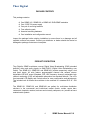
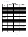
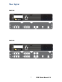
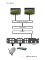
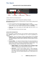
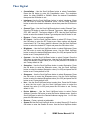
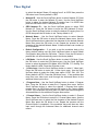
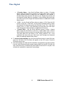
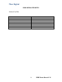
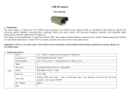
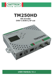
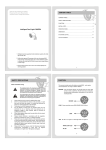
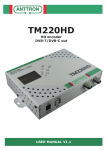
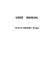
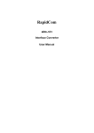
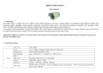
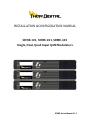
INSTALLATION &CONFIGURATION MANUAL SDME-101, SDME-201, SDME-401 Single, Dual, Quad Input QAM Modulators SDME Series Manual V1.0 Thor Digital TABLE OF CONTENTS SAFETY PRECAUTIONS.................................................................................................3 PACKAGE CONTENTS ...................................................................................................4 PRODUCT DESCRIPTION ..............................................................................................4 SPECIFICATIONS ..........................................................................................................5 INSTALLATION ............................................................................................................6 UNPACKING and INSPECTION ............................................................................................................................ 6 PRODUCT PICTURES and DIAGRAMS ..............................................................................................................6 SDME-101 .........................................................................................................................................................................6 SDME-201......................................................................................................................................................................7 SDME-401......................................................................................................................................................................7 HARDWARE INSTALLANTION and CONNECTIONS ...................................................................................8 MODULATOR SETUP AND CONFIGURATION .............................................................. 10 INITIAL SETUP TO FACTORY DEFAULT ...................................................................................................... 10 MODULATOR CONFIGURATION ...................................................................................................................... 10 SDME MODULATOR NOTES ....................................................................................... 14 2 SDME Series Manual V1.0 Thor Digital SAFETY PRECAUTIONS The presence of this symbol is to alert the installer and user to the presence of uninsulated dangerous voltages within the product’s enclosure that may be of sufficient magnitude to produce a risk of electric shock. TO REDUCE THE RISK OF FIRE OR ELECTRIC SHOCK, DO NOT EXPOSE THIS DEVICE TO RAIN OR MOISTURE. DO NOT OPEN THE UNIT. REFER SERVICING TO QUALIFIED PERSONNEL ONLY. DO NOT apply power to the unit until all connections have been made, all components have been installed and all wiring has been properly terminated. DO NOT terminate, change or uninstall any wiring without first disconnecting the unit’s power adapter from the device. This device is supplied with the appropriately rated 12VDC power supply with the center pin positive. The use of any other power supply could cause damage and invalidate the manufacturer’s warranty. DO NOT connect the power supply to the device if the power cord is damaged. DO NOT cut the power cord. DO NOT plug the power supply into an AC outlet until all cables and connections to the device have been properly connected. The device should be installed in an environment consistent with its operating temperature specifications. Placement next to heating devices and ducts is to be avoided as doing so may cause damage. The device should not be placed in areas of high humidity. DO NOT cover any of the device’s ventilation openings. DO NOT cover or obstruct the device’s fan or fan openings. If the device has been in a cold environment allow it to warm to room temperature for at least 2 hours before connecting to an AC outlet. 3 SDME Series Manual V1.0 Thor Digital PACKAGE CONTENTS This package contains: One SDME-101, SDME-201 or SDME-401 DVB-SDME modulator One 12VDC 3A power supply One pair of mounting brackets Four adhesive pads Assorted mounting hardware One installation and configuration manual Inspect the package before starting installation to ensure there is no damage and all supplied contents are present. Contact your distributor or dealer should the device be damaged or package contents are incomplete. PRODUCT DESCRIPTION Thor Digital’s SDME modulators convert Digital Video Broadcasting (DVB) standard definition video and audio signals to QAM DVB-C (Digital Video Broadcasting over Cable). The SDME-101, SDME-201 and SDME-401 provide respectively single, dual and quad inputs. All units feature programmable channel and network names. Adjustable VHF/UHF output (Standard, IRD, HRC frequency channel), adjustable logic channel numbering (LCN) and adjustable attenuation are standard features. The unit’s front-mounted LCD display and controls allow for easy configuration and adjustments. The included rack kit allows the modulator to be mounted in a standard EIA 19” 1RU rack. The SDME-101, SDME-201 and SDME-401 are perfect for multi-video distribution solutions in the commercial and institutional market (hotels, motels, sports bars, restaurants, hospitals, casinos, business and university campuses, etc.) as well as home entertainment systems. 4 SDME Series Manual V1.0 Thor Digital SPECIFICATIONS SDME-101 SDME-201 SDME-401 Video Input Composite/ASI Composite/ASI Composite/ASI Video Input Level 0.7 – 1.4V(peak-to peak) 0.7 – 1.4V(peak-to-peak) 0.7 – 1.4V (peak-to-peak) Video Mode NTSC/PAL NTSC/PAL NTSC/PAL Audio input Stereo Stereo Stereo Audio Input Level 0.4 – 4.8V (p-to-p) 0.4 – 4.8V (p-to-p) 0.4 – 4.8V (p-to-p) Video and Audio Input Connectors RCA RCA RCA Input Impedance 75Ω 75Ω 75Ω Frequency Range 57-861MHz 57-861MHz 57-861MHz Output Level 25dBmV 25dBmV 25dBmV Output Impedance 75Ω 75Ω 75Ω Channel Bandwidth 6HMz 6MHz 6MHz Channel Level Adjustment 20 dB typical 20 dB typical 20 dB typical MER 36 dB typical 36 dB typical 36 dB typical Connector Type “F” female “F” female “F” female Video Resolution NTSC 720x480@30fps NTSC 720x480@30fps NTSC 720x480@30fps Video Compression MPEG2 MP@ML MPEG2 MP@ML MPEG2 MP@ML Audio Compression MPEG1 Layer II MPEG1 Layer II MPEG1 Layer II Constellations 64 QAM / 256 QAM 64 QAM / 256 QAM 64 QAM / 256 QAM Symbol Rate 5.056941 Msps @64QAM 5.360537 Msps @256QAM 5.056941 Msps @64QAM 5.360537 Msps @256QAM 5.056941 Msps @64QAM 5.360537 Msps @256QAM Data Rate 26.97035 Mbps @64QAM 38.81070 Mbps @256QAM 26.97035 Mbps @64QAM 38.81070 Mbps @256QAM 26.97035 Mbps @64QAM 38.81070 Mbps @256QAM Power Supply 12VDC @3A 12VDC @3A 12VDC @3A Power Consumption 1110mA (13.2W) 1300mA (15.6W) 1700mA (20.4W) Display Language English English English Dimensions 11.8” x 7.87” x 18.5” 11.8” x 7.87” x 18.5” 11.8” x 7.87” x 18.5” Weight 3.65 lb. 3.78 lb. 4.09 lb INPUT OUTPUT MODULATION GENERAL Specifications are subject to change without prior notice 5 SDME Series Manual V1.0 Thor Digital INSTALLATION System Installer must adhere to Article 820-40 of the NEC that provides guidelines for proper grounding and specifies that the cable ground shall be connected to the grounding system of the building, as close to the point of cable entry as possible. UNPACKING and INSPECTION Each unit is shipped factory tested. Ensure all items are removed from the container prior to discarding any packing material. Thoroughly inspect the unit for shipping damage with particular attention to connectors and controls. If there is any sign of damage to the unit or damaged or loose connectors contact your distributor immediately. Do not put the equipment into service if there is any indication of defect or damage. PRODUCT PICTURES and DIAGRAMS SDME-101 6 SDME Series Manual V1.0 Thor Digital SDME-201 SDME-401 7 SDME Series Manual V1.0 Thor Digital HARDWARE INSTALLANTION and CONNECTIONS 1. The unit can be rack mounted in a standard EIA 19” rack. Attach the rack mounts if the unit is to be installed in a rack. 2. Use a 75Ωcoaxial cable with RCA connectors to connect the video source (e.g., CATV, DVD, VCR, Camera) to the unit’s yellow RCA VIDEO INPUT jack(IN1…IN4 depending on the SDME model). Repeat this step for each video source connection. It is highly recommended that quality coaxial cable and connectors be used for all video source connections. 3. Use RCA cables to connect the audio source to the red / white AUDIO L and AUDIO R INPUT jacks (IN1…IN4 depending on the SDME model). Use the red and white jacks for audio input or either one for a single input. Repeat this step for each audio source connection. Be sure the video and audio connections for each source are consistent with the unit’s inputs (IN1…IN4 depending on the SDME model). It is highly recommended that quality cables and connectors be used for all audio source connections. 4. Use a quality 75Ω coaxial cable with “F” connectors from the unit’s RF OUT jack to the distribution system (combiner or reverse splitter) or directly to a television. 5. Connect the included 12VDC 3A power supply to the unit’s DC 12V POWER jack. 6. Connect the 12VDC 3A power supply to an appropriately rated AC power outlet. 8 SDME Series Manual V1.0 Thor Digital Building Distribution Network Launch Amplifier Combiner SDME-401 9 SDME Series Manual V1.0 Thor Digital MODULATOR SETUP AND CONFIGURATION Reset LCD Display Scroll Up/Down Enter (OK) INITIAL SETUP TO FACTORY DEFAULT The SDME’s front panel is used to configure the modulator as desired. Before performing a configuration it is advised that the “Factory Default” settings should be initialized as follows: Power up the device and wait until the booting process is complete. Once complete, press the Scroll Up/Down button until “Default Config” appears in the menu. After “Default Config” appears press the OK button. Power down the unit by removing the power supply cable from the DC 12V power jack. Wait 5 seconds and re-connect the power supply. MODULATOR CONFIGURATION Once the modulator is powered back up it will go through an internal booting process. When “Running” appears in the LCD Display the unit is ready for programming or operation. Password – Press the OK button to select a 4-digit password. Use the Scroll Up/Down button to search and select individual numbers for the password. The default password is 0000. Press the OK button for each number to set the password. Advanced Menu – To access the Advanced Menu first enter the password by pressing the OK button. Once the correct password is entered press the OK button and the LCD Screen will display “Advanced Menu Output Channel”. The following configuration options are available under Advanced Menu: Output Channel – Use the Scroll Up/Down button to change the output channel. Channels 2 to 135 are available. Once the desired output channel is selected press the OK button to set the channel. Attenuation – Use the Scroll Up/Down button to select Attenuation. Press the OK button to enter the Attenuation menu. Use the Scroll/Up down button to select the desired attenuation in 1dB increments from 0 to minus 20 dB. Once the desired attenuation level is found press the OK button to set. 10 SDME Series Manual V1.0 Thor Digital Constellation – Use the Scroll Up/Down button to select Constellation. Press the OK button to enter the Constellation menu. The modulator allows for either QAM256 or QAM64. Select the desired Constellation then press the OK button to set. Interleaver–Use the Scroll Up/Down button to select Interleaver. Press the OK button to enter the Interleaver menu. Use the Scroll Up/Down button to select the desired Interleaver values then press the OK button to set. Channel Type – Use the Scroll Up/Down button to select Channel Type. Press the OK button to enter the Channel Type menu. Menu options are STD, HRC and IRC. The factory default is STD. Use the Scroll Up/Down button to select the desired Channel Type and press the OK button to set. Reserve – Factory set and not adjustable. RF Output – Use the Scroll Up/Down button to select RF Output. Press the OK button to enter the RF Output menu. Menu options are Normal, Inverted and C.W. The factory default is Normal. Use the Scroll Up/Down button to select the desired RF Output and press the OK button to set. Brightness – Use the Scroll Up/Down button to select Brightness. Press the OK button to enter the Brightness menu. Use the Scroll Up/Down button to select the desired Brightness value (0 to 255) and press the OK button to set. Factory default is 128 Contrast – Use the Scroll Up/Down button to select Contrast. Press the OK button to enter the Contrast menu. Use the Scroll Up/Down button to select the desired Contrast value (0 to 255) and press the OK button to set. Factory default is 128. Saturation – Use the Scroll Up/Down button to select Saturation. Press the OK button to enter the Saturation menu. Use the Scroll Up/Down button to select the desired Saturation value (0 to 255) and press the OK button to set. Factory default is 128. Sharpness – Use the Scroll Up/Down button to select Sharpness. Press the OK button to enter the Sharpness menu. Use the Scroll Up/Down button to select the desired Sharpness value (0 to 255) and press the OK button to set. Factory default is 64. Hue – Use the Scroll Up/Down button to select Hue. Press the OK button to enter the Hue menu. Use the Scroll Up/Down button to select the desired Hue value (0 to 255) and press the OK button to set. Factory default is 128. Device Address – Use the Scroll Up/Down button to select Device Address. Press the OK button to enter the Device Address menu. Use the Scroll Up/Down to select the Desired Address ranging from 1 to 32 then press the OK button to set. Reserve – Factory set and not adjustable. Stream ID–Use the Scroll Up/Down button to select Stream ID. Press the OK button to enter the Stream ID menu. Use the Scroll Up/Down button 11 SDME Series Manual V1.0 Thor Digital to select the desired Stream ID ranging from 0 to 65535 then press the OK button to set. Factory default is 1000. Network ID – Use the Scroll Up/Down button to select Network ID. Press the OK button to enter the Network ID menu. Use the Scroll Up/Down button to select the desired Network ID ranging from 0 to 65535 then press the OK button to set. Factory default is 100. ORG Network ID – Use the Scroll Up/Down button to select ORG Network ID. Press the OK button to enter the ORG Network ID menu. Use the Scroll Up/Down button to select the desired ID ranging from 0 to 65535 then press the OK button to set. Factory default is 10. Network Name – Use the Scroll Up/Down button to select Network Name. Press the OK button to enter the Network Name menu. Use the Scroll Up/Down button to select the first character for the desired Network Name then press the OK button to set. Repeat the process for each character in the desired Network Name. A Network Name can consist up to 16 characters. Default Configuration – If you wish to set the modulator back to the factory default settings use the Scroll Up/Down button to reach Default Configuration then press the OK button. Caution: Once the OK button is pressed the unit will automatically reset to the factory default. LCN Mode – Use the Scroll Up/Down button to select LCN Mode. Press the OK button to enter the LCN Mode menu. Use the Scroll Up/Down button to select the desired LCN Mode: APN, EACEM, ITC, NorDig. The factory default is APN. Press the OK button to set. 1 Video Input –Use the Scroll Up/Down button to select 1 Video Input. Press the OK button to enter the 1 Video Input menu. Use the Scroll Up/Down button to select the Video Input option: NTSC, PAL, ASI. The factory default is NTSC. Press the OK button to set. If the modulator has more than one video input scroll through the Advanced Menu for the additional video input menus. 1 Program Num – Use the Scroll Up/Down button to select 1 Program Num. Press the OK button to enter the 1 Program Num menu. Use the Scroll Up/Down button to select the desired 1 Program Num option ranging from 0 to 65535 then press the OK button to set. Factory default is 1001. If the modulator has more than one video input scroll through the Advanced Menu for the additional Program Num menus. 1 Channel Name – Use the Scroll Up/Down button to select 1 Channel Name. Press the OK button to enter the 1 Channel Name menu. Use the Scroll Up/Down menu to select the first character of the desired Channel Name then press the OK button to set. Repeat the process until the Channel Name is completed. If the modulator has more than one video input scroll through the Advanced Menu for additional channel name menus. 12 SDME Series Manual V1.0 Thor Digital 1 Provider Name – Use Scroll Up/Down button to select 1 Provider Name. Press the OK button to enter the 1 Provider Name menu. Use the Scroll Up/Down button to select the first character of the desired 1 Provider Name then press the OK button to set. Repeat the process until the desired Provider Name is completed. If the modulator has more than one video input scroll through the Advanced Menu for additional Provider Name menus. 1 LCN – Use the Scroll Up/Down button to select 1 LCN. Press the OK button to enter the 1 LCN menu. Use the Scroll Up/Down button to select the desired LCN value then press the OK button to set. The 1 LCN value range is from 1 to 999. If the modulator has more than one video input scroll through the Advanced Menu for additional LCN menus. 1 Aspect Ratio – Use the Scroll Up/Down button to select 1 Aspect Ratio. Press the OK button to enter the 1 Aspect Ratio menu. Use the Scroll Up/Down button to select the desired Aspect Ratio option of 4:3 or 16:9 then press the OK button to set. Factory default is 4:3. If the modulator has more than one video input scroll through the Advanced Menu for additional Aspect Ratio menus. To exit the Advanced Menu use the Scroll Up/Down button to select Exit then press the OK button. Exit Exit Menu will appear on the LCD screen. Press the OK button twice to exit. Once the settings are made and the modulator is programmed (a) remove power from the unitby disconnecting the power supply cable from the DC 12V jack, (b) wait 5 seconds and (c) reconnect the power cable to the unit’s DC 12V jack. This will allow the modulator to capture the new settings. 13 SDME Series Manual V1.0 Thor Digital SDME MODULATOR NOTES PRODUCT NOTES: ITEM PASSWORD SERIAL NUMBER INSTALLATION DATE PURCHASE DATE VIDEO 1 INPUT VIDEO 2 INPUT VIDEO 3 INPUT VIDEO 4 INPUT VALUE 14 SDME Series Manual V1.0