1
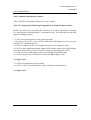
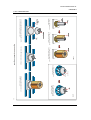
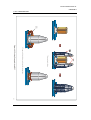
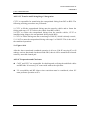
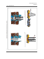
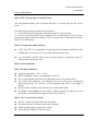
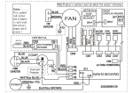
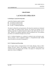
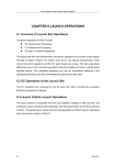
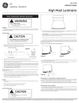
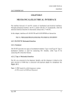
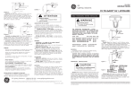
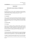
LM-2E USER’S MANUAL
CHAPTER 8
CALT'S PROPRIETARY
CHAPTER 8
LAUNCH SITE OPERATION
Launch Site Operation mainly includes:
z LV Checkouts and Processing;
z SC Checkouts and Processing;
z SC and LV Combined Operations.
The typical working flow and requirements of the launch site operation are introduced
in this chapter. For different launch missions, the launch site operation will be
different, especially for combined operations related to joint efforts from SC and LV
sides. Therefore, the combined operations could be performed only if the operation
procedures are coordinated and approved by all sides.
LM-2E uses JSLC and XSLC as its launch sites. The launch site operations in the two
launch sites are described as follows.
Part A: Launch Operations in JSLC
Two-stage LM-2E and LM-2E/ETS are launched from in JSLC.
A8.1 LV Checkouts and Processing
Two-stage LM-2E or LM-2E/ETS launch vehicle is transported from CALT facility
(Beijing, China) to JSLC (Gansu Province, China), and undergoes various checkouts
and processing in South Technical Center and South Launch Center of JSLC. The
typical LV working flow in the launch site is shown in Figure A8-1.
Issue 1999
8-1
LM-2E USER’S MANUAL
CALT'S PROPRIETARY
CHAPTER 8
Day
1
2
3
4
5
6
7
8
9
10
11
12
13
14
15
Figure A8-1 LV Working Flow in JSLC
16
18
19
In Technical
Center
17
20
21
23
24
In Launch
Center
22
8-2
8-2
Issue 1999
LM-2E USER’S MANUAL
CHAPTER 8
CALT'S PROPRIETARY
A8.2 Combined Operation Procedures
Take LM-2E/ETS launching multiple SCs as an example:
A8.2.1 SC Integration and Fairing Encapsulation in South Technical Center
In BS3, SC team carries out all the SC operations. LV side is responsible for mating
SCs with dispenser and installing SC separation devices. The following describes the
typical working procedure:
1. CALT to bolt the dispenser on the supporting table;
2. SC team to lift up SCs, and CALT to mate them with dispenser one by one and
install SC/LV separation devices;
3. CALT to complete the SC/LV integration and form a SC/Dispenser stack;
4. CALT to mate OMS with payload adapter in BLS and to transfer the OMS/Adapter
stack from BLS to BS3; CALT to set up the fairing encapsulation pad in BS3.
5. CALT to bolt the OMS/Adapter stack on the fairing encapsulation pad;
6. CALT to integrate the SC/Dispenser stack with OMS/Adapter stack.
See Figure A8-2.
7. CALT to encapsulate the fairing in BS3;
8. CALT to remove the fairing fixture, and to install the hoisting basket;
See Figure A8-3.
Issue 1999
8-3
LM-2E USER’S MANUAL
CALT'S PROPRIETARY
CHAPTER 8
1. To bolt the dispenser on
supporting table.
2. To mate the spacecraft with
the dispenser one by one.
4. To transfer the OMS/Adapter stack from BLS to BS3,
and to set up the fairing encapsulation pad.
In BS3
3. To complete the integration and
form a SC/Dispenser stack.
5. To bolt the OMS/Adapter stack on the pad.
Figure A8-2 Payload/LV Integration
Payload Adapter
Supporting
Table
a). To bolt Payload Adapter
on a supporting table.
In BLS
b). To mate the OMS with
Payload Adapter, and form
a OMS/Adapter stack
6. To integrate the SC/Dispenser stack
with OMS/Adapter stack.
8-4
8-4
Issue 1999
LM-2E USER’S MANUAL
CALT'S PROPRIETARY
CHAPTER 8
Hoisting
Basket
7. To encapsulate the fairing.
8. To remove the fairing fixture, and to install the hoisting basket.
Figure A8-3 Fairing Encapsulation in BS3
8-5
8-5
Issue 1999
LM-2E USER’S MANUAL
CHAPTER 8
CALT'S PROPRIETARY
A8.2.2 SC Transfer and Fairing/Stage-2 Integration
CLTC is responsible for transferring the encapsulated fairing from BS3 to BLS. The
following working procedures are performed:
9. CLTC to lift the encapsulated fairing onto the transfer vehicle and to fasten the
fairing with ropes; CLTC to drive the vehicle from BS3 to BLS;
10.CLTC to release the encapsulated fairing from the transfer vehicle; CLTC to
install hoisting slings to the encapsulated fairing inside BLS;
11.CLTC to lift the fairing onto the second stage of LM-2E, which is already erected;
12. CALT to mate the encapsulated fairing with stage-2 of LM-2E. This is the end of
the combined operations.
See Figure A8-4.
After the above-mentioned combined operation is all over, LM-2E carrying SCs will
undergo various functional checkouts inside BLS, then it will be transferred to launch
center by moveable launch pad.
A8.3 SC Preparation and Checkouts
z
CALT and CLTC are responsible for checking and verifying the umbilical cables
and RF links. If necessary, SC team could witness the operation.
z
LV accessibility and RF silence time restriction must be considered, when SC
team performs operation to SCs.
Issue 1999
8-6
LM-2E USER’S MANUAL
CALT'S PROPRIETARY
CHAPTER 8
9. To lift the encapsulated fairing stack onto the transfer vehicle, and to
drive the vehicle from BS3 to BLS.
11. To lift up the encapsulated fairing onto the LM-2E.
10. To move the encapsulated fairing stack into BLS and install hoisting
sling.
12. To mate the encapsulated fairing with stage-2 of LM-2E.
Figure A8-4 Payload Transfer and Fairing/stage-2 integration
8-7
8-7
Issue 1999
LM-2E USER’S MANUAL
CHAPTER 8
CALT'S PROPRIETARY
A8.4 Launch Limitation
A8.4.1 Weather Limitation
z
z
z
z
z
z
Ambient temperature: -10°C~+40°C;
Relative humidity: ≤98% (corresponding to 20±5°C)
The average ground wind velocity in the launch area is lower than 10m/s
The winds aloft limitation: q×α≤3400N/m2•rad (q×α reflects the aerodynamic
loads acting on the LV, whereas, q is the dynamic head, and α is LV angle of
attack.)
The horizontal visibility in the launch area is farther than 20km.
No thunder and lightning in the range of 40km around the launch area, the
atmosphere electrical field strength is weaker than 10kV/m.
A8.4.2 "GO" Criteria for Launch
z
z
z
z
The SCs' status is normal, and ready for launch.
The launch vehicle is normal, and ready for launch.
All the ground support equipment is ready;
All the people withdraw to the safe area.
A8.5 Pre-launch Countdown Procedure
The typical pre-launch countdown procedure in the launch day is listed below:
No.
1
2
3
4
5
Time
-6 hours
-5 hours
-4 hours
-2 hours
-80 minutes
6
-60 minutes
7
8
-50 minutes
-40 minutes
Issue 1999
Event
Preliminary Calculation by Flight Software
Functional Checkouts on Each Sub-system
GSE Withdrawal, LV Status Checkouts, Sealing
Preparing to Move Back the Service Tower
Moving Back the Service Tower;
Accurately aiming;
Ground Telemetry and Tracking Systems Power-on;
Preliminarily Loading Flight Software;
Loading PUS Software;
Tank Pressurization
Gas Pipes and Air-conditioning Pipes Drop-off;
Flight Software Loading;
SC Power Switch-over;
8-8
LM-2E USER’S MANUAL
CHAPTER 8
CALT'S PROPRIETARY
9
-5 minutes
10
-60 seconds
11
12
13
-30 seconds
-7 seconds
0 seconds
On-board Telemetry and Tracking Systems Power-on
Telemetry, Tracking and Propellant Utilization Systems Power
Switch-over;
Control System Power Switch-over;
Control System, Telemetry System and Tracking System
Umbilical Disconnection;
Moving Back the Cable Swing Arms;
TT&C Systems Starting;
Camera on;
Ignition.
A8.6 Post-launch Activities
The orbital parameters of the injected orbit will be provided to Customer in half-hours
after SC injection.
The launch evaluation report will be provided to the Customer in a month after
launch.
Issue 1999
8-9
LM-2E USER’S MANUAL
CHAPTER 8
CALT'S PROPRIETARY
Part B: Launch Operations in XSLC
Two-stage LM-2E and LM-2E/EPKM are launched from XSLC.
B8.1 LV Checkouts and Processing
The launch vehicle is transported from CALT facility (Beijing, China) to XSLC
(Sichuan Province, China), and undergoes various checkouts and processing in
Technical Center and Launch Center of XSLC. The typical LV working flow in the
launch site is shown in Table 8-1.
Table 8-1 LV Working Flow in the Launch Site
No. Item
Working
Accumulative
Period
Period
1
To Unload LV from the Train and Transfer LV to BL1.
1 day
1 day
2
Unit Tests of Electrical System
7 days
8 days
3
Tests to Separate Subsystems
3 days
11 days
4
Matching Test Among Subsystems
4 days
15 days
5
Three Overall Checkouts
4 days
19 days
6
Review on Checkout Results
1 day
20 days
7
LV Status Recovery before Transfer
2 days
22 days
8
To Transfer LV to Launch Center
1 days
23 days
L
9
Erecting LV on the Launch Pad
2 days
25 days
A
10
Tests to Separate Subsystems
3 days
28 days
U
11
Matching Test Among Subsystems
3 days
31 days
N
12
The first and second overall checkouts
2 days
33 days
C
13
To Transfer SC/Fairing Stack to Launch Center
1 days
34 days
H
14
EMC Testing
1 days
35 days
15
The Third Overall Checkout (SC Involved)
1 day
36 days
C
16
The Fourth Overall Checkout
1 day
37 days
E
17
Review on Checkout Results
1 day
38 days
N
18
Functional Check before Fueling, Gas Replacement of Tanks
2 days
40 days
T
19
N2O4/UDMH Fueling Preparation
1 days
41 days
E
20
N2O4/UDMH Fueling
0.5 day
41.5 days
21
Launch
0.5 days
42 days
42 days
42 days
T
E
C
H
.
R
Total
Issue 1999
8-10
LM-2E USER’S MANUAL
CHAPTER 8
CALT'S PROPRIETARY
After the SC is transferred to Launch Center, some of SC and LV operations can be
performed in parallel under conditions of no interference.
B8.2 Combined Operation Procedures
Take LM-2E/EPKM launching GTO satellite as an example.
B8.2.1 SC Integration and Fairing Encapsulation in Technical Center
In BS3, SC team carries out all the SC operations. CALT is responsible for mating SC
with EPKM and installing the separation devices. The following describes the
working procedure:
1. CALT to bolt the LV adapter on the fairing encapsulation pad;
2. CALT to mate the interface adapter with LV adapter, and install clampband
system;
3. CALT to bolt EPKM with interface adapter;
4. SC team to install SC adapter on the SC;
5. SC team to lift up SC and move SC onto the EPKM;
6. CALT to bolt SC adapter with EPKM;
7. CALT to encapsulate the fairing in BS3;
8. CALT to remove the fairing fixture, and to install the hoisting basket;
B8.2.2 SC Transfer
CLTC is responsible for transferring the encapsulated fairing from BS3 to Launch
Center.
The following working procedures are performed:
9. CLTC to lift the encapsulated fairing onto the special vehicle and to fasten the
fairing with ropes; CLTC to connect the air-conditioning to the fairing if necessary;
CLTC to drive the vehicle from BS3 to Launch Service Tower;
10. CLTC to release the encapsulated fairing from the transfer vehicle; CLTC to
install slings to the encapsulated fairing under the Launch Service Tower; CLTC to
lift the fairing onto the 8th floor of the tower;
Issue 1999
8-11
LM-2E USER’S MANUAL
CHAPTER 8
CALT'S PROPRIETARY
B8.2.3 SC/LV Integration in Launch Center
The encapsulated fairing will be mated with the LV second stage on the service
tower.
The following working procedures are performed:
11. CALT to hoist the encapsulated fairing above the LV second stage;
12. CALT to joint the bottom of the fairing with LV second stage; CLTC to remove
the hoisting basket outside the fairing; CLTC to connect the SC umbilical connectors
and SC air-conditioning.
B8.3 SC Preparation and Checkouts
z
CALT and CLTC are responsible for checking and verifying the umbilical cables
and RF links. If necessary, SC team could witness the operation.
z
LV accessibility and RF silence time restriction must be considered, when SC
team performs operation to SC.
B8.4 Launch Limitation
B8.4.1 Weather Limitation
z
z
z
z
z
z
Ambient temperature: -10°C~+40°C;
Relative humidity: ≤98% (corresponding to 20±5°C)
The average ground wind velocity in the launch area is lower than 10m/s
The winds aloft limitation: q×α≤3400N/m2•rad (q×α reflects the aerodynamic
loads acting on the LV, whereas, q is the dynamic head, and α is LV angle of
attack.)
The horizontal visibility in the launch area is farther than 20km.
No thunder and lightning in the range of 40km around the launch area, the
atmosphere electrical field strength is weaker than 10kV/m.
B8.4.2 "GO" Criteria for Launch
z
z
z
z
The SC’s status is normal, and ready for launch.
The launch vehicle is normal, and ready for launch.
All the ground support equipment is ready;
All the people withdraw to the safe area.
Issue 1999
8-12
LM-2E USER’S MANUAL
CHAPTER 8
CALT'S PROPRIETARY
B8.5 Pre-launch Countdown Procedure
The typical pre-launch countdown procedure in the launch day is listed below:
No.
Time
Event
1
-6 hours
Preliminary Calculation by Flight Software
2
-5 hours
Functional Checkouts on Each Sub-system
3
-4 hours
GSE Withdrawal, LV Status Checkouts, Sealing
4
-2 hours
Preparing to Move Back the Service Tower
5
-80 minutes
Moving Away the Service Tower;
Accurately aiming;
Ground Telemetry and Tracking Systems Power-on;
6
-60 minutes
Preliminarily Loading Flight Software;
Loading PUS Software;
7
-50 minutes
Tank Pressurization
8
-40 minutes
Gas Pipes and Air-conditioning Pipes Drop-off;
Flight Software Loading;
SC Power Switch-over;
On-board Telemetry and Tracking Systems Power-on
9
-5 minutes
Telemetry, Tracking and Propellant Utilization Systems Power
Switch-over;
10
-60 seconds
Control System Power Switch-over;
Control System, Telemetry System and Tracking System
Umbilical Disconnection;
Moving Back the Cable Swing Arms;
11
-30 seconds
TT&C Systems Starting;
12
-7 seconds
Camera on;
13
0 seconds
Ignition.
B8.6 Post-launch Activities
The injection parameters will be provided to Customer in half-hours.
The launch evaluation report will be provided to the Customer in a month after
launch.
Issue 1999
8-13