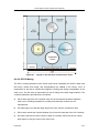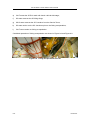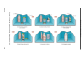
1
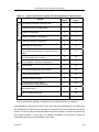
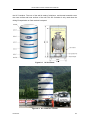
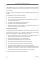
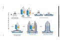
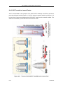
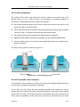
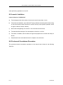
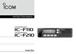
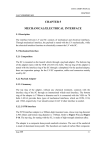
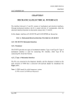
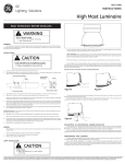
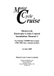
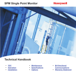
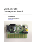
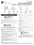
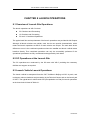
LM-3A Series Launch Vehicle User’s Manual CHAPTER 8 LAUNCH OPERATIONS 8.1 Overview of Launch Site Operations The launch operations at XSLC include: SC Checkout and Processing LV Checkout and Processing SC and LV Combined Operations The typical work flow and requirements of the launch operations are provided in this Chapter. Although all launch missions are similar, each has its own special characteristics, which means the launch operations at XSLC for each mission are unique. The main area where differences occur is the combined operations where the satellite and launch vehicle teams interface directly. Thus combined operations can only be successfully performed if the operational procedures are fully coordinated and approved by both sides. 8.2 SC Operations at the Launch Site The SC operations are conducted by the SC team with XSLC providing the necessary facilities and support as required. 8.3 Launch Vehicle Launch Operations The launch vehicle is transported from the CALT facilities in Beijing to XSLC by train, and undergoes various checkouts and processing in the Technical Center and on the launch pad of XSLC. The typical launch vehicle work flow (Encapsulation-on-Pad) for launch operations at the launch site is listed in Table 8-1. 8-1 Issue 2011 LM-3A Series Launch Vehicle User’s Manual Technical Center Table 8-1 Typical Launch Vehicle Work Flow (Encapsulation-on-Pad) at XSLC Working Accumulative Activity day(s) day(s) LV unloading from train & moving to BL1 1 1 LV status recovery for system tests 1 2 Unit tests of subsystem 3 5 LV status preparation for transport 2 7 LV transfer, erection & integration 1 8 Preparation for system tests 1 9 4 13 2 15 Transfer SC & fairing to launch pad SC/LV integration & fairing encapsulation 2 17 SC Test Period 1 18 Third overall checkout with SC involved 1 19 Fourth overall checkouts 1 20 Review on checkout results 1 21 Functional check before fueling Gas replacement of propellant tanks 1 22 N2O4/UDMH fueling 1 23 LOX/LH2 fueling and launch 1 24 Launch Pad Tests of subsystems SC/LV combined operations in Technical Center in parallel First and second overall checkouts SC encapsulated with container Total 24 days Note: After the SC is transferred to the launch pad, some of the SC and LV operations can be performed in parallel as detailed in the combined operation procedures. If encapsulation is performed in BS3, the SC and fairing are integrated as a complete unit. The integrated SC and fairing are transferred to the launch pad, and mated with the launch vehicle. The SC/LV mating is performed after the second overall LV checkout and before the third overall checkout. In this case, the working procedures for the launch vehicle are substantially the same as encapsulation on the pad. Issue 2011 8-2 LM-3A Series Launch Vehicle User’s Manual 8.4 SC/LV Combined Operations 8.4.1 General Description The SC/LV combined operations are conducted at the Technical Center and the launch pad. LM-3A Series launch vehicles offer two options for the SC to LV integration: Encapsulation-on-Pad and Encapsulation-in-BS3. Encapsulation-on-Pad (Refer to Section 8.4.2): The Payload Adapter (PLA) and fueled SC are mated inside BS3. The SC/PLA stack is put into the SC Container, which is sealed and then shipped to launch pad. The SC Container and fairing are hoisted to the 8th floor of the Service Tower of Launch Complex No.2 (LC-2). A clean room is established there on the tower following the arrival of SC Container and fairing. The SC/LV integration and fairing encapsulation are performed on the 8th floor of the Service Tower. Encapsulation-in-BS3 (Refer to 8.4.3): The Payload Adapter (PLA) and fueled SC are mated in BS3. The SC/PLA stack is then encapsulated with the fairing. The integrated SC/Fairing is shipped to launch pad, and mated with launch vehicle. The remote SC ground equipment will be moved to the launch complex and the functional checkout will be completed before the SC/LV combined operations commence. The launch rehearsal and launch countdown procedures are part of the SC/LV combined operations, so the SC team is required to participate in and perform the SC operations and checkouts, as detailed in the procedures. 8.4.2 SC/LV Combined Operations for Encapsulation-on-Pad 8.4.2.1 SC Container SC Container is a dedicated container used for transferring the SC from BS3 to the launch pad (Figure 8-1 and Figure 8-2). The SC Container is 4,120 mm in diameter, 8,070 mm in height and the usable envelope of SC Container is 3,650 mm in diameter and 6,650 mm in height for the 1194/1194A PLA. See Figure 8-1. The SC Container is composed of a base pad and five cylindrical sections. The five sections can be assembled together one by one. Two guide poles are provided outside 8-3 Issue 2011 LM-3A Series Launch Vehicle User’s Manual the SC Container. The core of the wall is made of aluminum, and thermal materials cover the outer surface and inner surface of the wall. This SC Container is only used when the fairing Encapsulation-on-Pad method is adopted. Figure 8-1 Figure 8-2 Issue 2011 SC Container SC Container Transfer 8-4 LM-3A Series Launch Vehicle User’s Manual If the satellite dimensions in launch configuration exceed the allowable static envelope of the SC Container, the interference must be reviewed and accepted by CALT in advance of the launch campaign. In addition, a bigger SC Container with 3,850 mm allowable envelope diameter is also available. The characteristics of the SC Container are as follows: a) SC/PLA stack is fastened inside the SC Container; b) The SC Container is filled and pressurized with dry nitrogen gas (N2) so that the SC is protected by a positive pressure; c) The maximum vertical and horizontal overload factor is 0.5 g; d) The satellite container is fitted with thermal insulation; e) Temperature, humidity, noise and acceleration, etc. inside the SC Container can be monitored and recorded during the transportation. 8.4.2.2 SC/LV Integration The PLA and the SC are mated in BS3 after the SC is fueled and weighed. The SC team carries out all the SC operations. CALT is responsible for mating the SC with the PLA and installing SC/LV clampband. The integration procedures are as follows: a) The Payload Adapter (PLA), with the clampband in the pre-installation position, is installed on a technological stand by the CALT operations team; b) SC is lifted and mated with PLA by the SC operations team; c) Clampband is locked and fastened by the CALT operations team; d) SC/LV separation connectors are mated by the SC operations team; e) SC/PLA stack is put into the SC container by the SC operations team; f) SC Container is sealed and filled with dry N2 by the CALT operations team; g) SC Container is ready for transfer to Launch Center. Environmental sensors are already installed on the inner side of the container, which can measure and record the inner environmental parameters in real-time during transfer to the Launch Center. The SC/LV integration process in BS3 is shown in Figure 8-3. 8-5 Issue 2011 Issue 2011 SC/LV integration process LM-3A Series Launch Vehicle User’s Manual Figure 8-3 8-6 LM-3A Series Launch Vehicle User’s Manual 8.4.2.3 SC Transfer XSLC is responsible for using the special vehicle to transfer the SC container to the launch pad. See Figure 8-4 and Figure 8-5. XSLC lifts the SC container, which already contains the SC/PLA stack, onto the special vehicle and fastens the SC container to the vehicle. XSLC drives the special vehicle from BS3 to the Service Tower at the launch pad (Figure 8-6). When in position under the crane, XSLC releases the SC Container from the transfer vehicle and lifts the SC Container up to the 8th floor of the Service Tower. See Figure 8-7 for the arrangement of the SC, Container and the Fairing on the Service Tower. All the doors on the 8th and upper floors are closed to establish the clean room conditions for the SC/LV mating operations; XSLC opens the SC container when the environmental conditions, including temperature, humidity and cleanness, achieve the SC requirements. 8-7 Issue 2011 Issue 2011 Transfer SC Container to the Launch Pad LM-3A Series Launch Vehicle User’s Manual Figure 8-4 8-8 LM-3A Series Launch Vehicle User’s Manual Figure 8-5 SC Container Transfer to the Launch Pad Figure 8-6 8-9 SC Container Lift Issue 2011 LM-3A Series Launch Vehicle User’s Manual Figure 8-7 Layout on the 8th floor of the Service Tower 8.4.2.4 SC/LV Mating The SC/LV mating operations at the launch pad include integrating the SC/PLA stack with the launch vehicle third stage, and encapsulating the satellite in the fairing. CALT is responsible for the launch vehicle third stage/PLA mating and fairing encapsulation in the clean room. The SC team is responsible for the SC lifting to the third stage interface. The combined operations procedures are as follows: a) XSLC team opens the SC Container when the environmental conditions inside the clean room, including temperature, humidity and cleanness, achieve the SC requirements; b) SC team begins to install the lifting slings on the SC after the container is open; c) XSLC team unbolts the Payload Adapter (PLA) from the base pad of the SC Container; d) SC team hoists and moves the SC/PLA stack to a position above the launch vehicle third stage by using the crane in the clean room; Issue 2011 8-10 LM-3A Series Launch Vehicle User’s Manual e) CALT mates the SC/PLA stack with launch vehicle third stage; f) SC team removes the SC lifting slings; g) XSLC team removes the SC Container from the Service Tower; h) SC team carries out the SC checkouts prior to the fairing encapsulation; i) CALT team carries out fairing encapsulation. Combined operations of fairing encapsulation are shown in Figure 8-8 and Figure 8-9. Figure 8-8 8-11 Faring Encapsulation-on-Pad Issue 2011 Issue 2011 Figure 8-9 LM-3A Series Launch Vehicle User’s Manual Combined operations of fairing Encapsulation-on-Pad 8-12 LM-3A Series Launch Vehicle User’s Manual The technical status of SC should be ready for flight before the fairing encapsulation. CALT is responsible for fairing encapsulation after both SC and launch vehicle teams confirm that the SC and the launch vehicle are ready for fairing encapsulation. After encapsulation of the fairing, the ground umbilical cable for the SC is connected to the onboard cable for the SC, and the fairing air-conditioning duct is connected to the fairing and the air-conditioning is turned on. The air-conditioning system maintains the environmental conditions inside the fairing so the clean room controls on the Service Tower 8th floor are relaxed. The SC team can only perform the limited closeout operations and checkouts for the SC through the access doors on the fairing. All functional testing is performed via the umbilical cable and the RF links. The combined operations procedures define the requirements for launch vehicle accessibility and RF silence time that must be respected by the SC team when performing operations on the SC. 8.4.3 SC/LV Combined Operations for Encapsulation-in-BS3 8.4.3.1 SC/LV Integration For fairing encapsulation in BS3, the combined operation procedures are as follows: a) SC team makes the final closeouts on the SC ready for encapsulation in the fairing; b) CALT team bolts the Payload Adapter (PLA) on a technological stand; c) SC team lifts the SC up and moves the SC to above the PLA; d) CALT team mates the SC with the PLA, and then installs the clampband with the support from the SC team; e) SC team checks the connection of the umbilical cable; f) CALT team unbolts the PLA from the working stand; g) SC team lifts up and moves the SC/PLA stack to the Transit Connector; h) CALT team bolts the SC/PLA stack on the Transit Connector; i) SC team removes the lifting slings from the SC/PLA stack; j) CALT team encapsulates the payload fairing on the SC/PLA stack. The SC/LV integration process in BS3 is shown in Figure 8-10. 8-13 Issue 2011 Issue 2011 SC/LV integration process in BS3 LM-3A Series Launch Vehicle User’s Manual Figure 8-10 8-14 LM-3A Series Launch Vehicle User’s Manual 8.4.3.2 SC Transfer to Launch Center XSLC is responsible for the transport of the SC/PLA/PLF assembly from BS3 to the launch pad using a special vehicle (Figure 8-11). XSLC drives the special vehicle from BS3 to LC-2 in the Launch Center and releases the SC/PLA/PLF stack from the transfer vehicle. The stack is then hoisted up to the 8th floor of the Service Tower. Figure 8-11 8-15 Transit of SC/PLA/PLF from BS3 to the Launch Pad Issue 2011 LM-3A Series Launch Vehicle User’s Manual 8.4.3.3 SC/LV Integration The mating of SC/PLA/PLF stack with launch vehicle is carried out on the 8th floor of the Service Tower at LC-2 of Launch Center. The procedures of combined operation of SC/PLA/PLF stack mating with launch vehicle are as follows: a) XSLC team installs the slings on SC/PLA/PLF stack, lifts the stack to the 8th floor, and moves the stack over launch vehicle; b) CALT team performs the SC/PLA/PLF stack mating with launch vehicle with the support from XSLC team. The mating is through bolts at the interface plane; c) XSLC team removes the slings away after Fairing stack/LV integration. d) Satellite ground umbilical cables are connected to the SC onboard umbilical cable; e) The air-conditioning duct is connected to the payload fairing and the air-conditioning for fairing is turned on. The SC/LV mating process is shown in Figure 8-12. Figure 8-12 SC/LV mating process 8.4.4 SC Preparation and Checkouts CALT and XSLC are responsible for checking and verifying the umbilical cables and RF links, and SC team may witness the operation if requested. The SC team can only perform the limited closeout operations and checkouts for the SC through the access doors on the fairing. All functional testing is performed via the umbilical cable and the RF links. The combined operations procedures define the requirements for launch vehicle accessibility and RF silence time that must be respected by the SC team Issue 2011 8-16 LM-3A Series Launch Vehicle User’s Manual when performing operations on the SC. 8.5 Launch Limitation Launch Criteria of “GO/NO GO" a) The average ground wind velocity in the launch area is lower than 10 m/s; b) The winds aloft limitation: qα ≤ 2500 N/m2•rad (qα reflects the aerodynamic loads acting on unit cross section area of the launch vehicle, where q is the dynamic pressure, and α is angle of attack of launch vehicle); c) No thunder and lightning in the area of 10 km around the launch site; d) The electrical field strength of the atmosphere is less than 10 kV/m. e) The status of satellite, launch vehicle and ground equipment are normal and ready for launch; f) All personnel have evacuated the launch complex to the safe area. 8.6 Pre-launch Countdown Procedure The typical pre-launch countdown procedure on the launch day is listed in the following Table 8-2. 8-17 Issue 2011 LM-3A Series Launch Vehicle User’s Manual Table 8-2 Typical Pre-Launch Countdown Procedure on the Launch Day Time Events 1 -7 hr LV Stage-3 LOX Fueling 2 -5 hr LV Stage-3 LH2 Fueling 3 -2 hr LV Control System power-on & functional checkout 4 -80 min LV Telemetry System power-on & functional checkout 5 -45 min Stopping & disconnecting of Fairing air-conditioning 6 -40 min 7 -22 min Stage-3 Engines pre-cooling Accurate aiming; Flight data presetting and checking; Gas pipe connectors for Stage-1, Stage-2 & boosters drop-off 8 -15~-10 min SC umbilical disconnection Telemetry and Tracking Systems power switch-over; 9 -4 min 10 -2 min Gas pipes disconnection of LV Stage-3 Fueling pipes disconnection of LV Stage-3 11 -90 sec Control System power switch-over 12 -60 sec 13 Umbilical disconnections of Control System & TT&C System Swinging off the supporting arms of Umbilical Tower 0 sec Ignition 8.7 Post-Launch Activities CLTC will provide the parameters of the injected orbit to the customer approximately thirty minutes after separation. CALT will provide the launch vehicle flight evaluation report to the customer two months after launch. Issue 2011 8-18