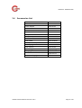
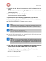
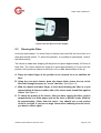
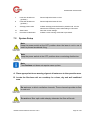
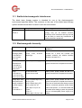
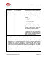
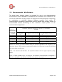
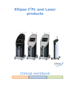
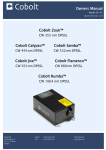
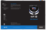
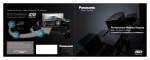
1
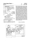
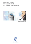
China Daheng Group, Inc. Diode Laser Therapy System OPERATION MANUAL Model: DenLase China Daheng Group, Inc. DenLase - SY A.0 CONTENTS CONTENTS 1 GENERAL ........................................................................... 4 1.1 User Guide ................................................................................................ 4 1.2 Introduction .............................................................................................. 4 1.4 Contraindications ..................................................................................... 6 2 SAFETY .............................................................................. 8 2.1 2.2 2.3 2.4 3 PRODUCT DESCRIPTION .............................................. 16 3.1 3.2 3.3 3.4 4 System Description ................................................................................ 16 Product Specifications........................................................................... 17 Laser Beam Delivery .............................................................................. 18 Accessories List ..................................................................................... 19 INSTALLATION ................................................................ 20 4.1 4.2 4.3 4.4 5 Proper Use ................................................................................................ 8 Safety Instructions ................................................................................. 10 Laser System Safety Features .............................................................. 14 Clinical Precautions for Laser Safety ................................................... 15 Installation Instructions ......................................................................... 20 Unpacking ............................................................................................... 20 Installation .............................................................................................. 21 Packing and Transporting the DenLase ............................................... 25 FIBER AND HANDPIECE ................................................ 26 5.1 5.2 5.3 5.4 Structure of an Optical Fiber ................................................................. 26 Stripping the Fiber ................................................................................. 27 Cleaving the Fiber .................................................................................. 29 Instruction for Using the Handpiece ..................................................... 31 6 DISINFECTION ................................................................ 32 7 OPERATION PROCEDURE ............................................. 33 7.1 Main Menu of Display ............................................................................. 33 7.2 System Setup.......................................................................................... 34 OPERATIONAL MANUAL DenLase-SY A.0 Page 2 of 50 CONTENTS 7.3 Settings ................................................................................................... 36 8 LABELS, SIGNS AND WARNINGS ................................. 40 8.1 Rating Labels .......................................................................................... 40 8.2 Warning and Informational Signs ......................................................... 41 8.3 Danger: Laser in Use ............................................................................. 42 9 TROUBLESHOOTING ..................................................... 43 9.1 Malfunctions With Error Messages ....................................................... 43 9.2 Malfunctions Without Error Messages ................................................. 44 10 LIMITED WARRANTY ...................................................... 45 11 ELECTROMAGNETIC COMPATIBILITY ......................... 46 11.1 11.2 11.3 Emitted electromagnetic Interference ............................................... 47 Electromagnetic Immunity ................................................................. 47 Recommended Safe Distance ............................................................ 49 12 CONTACT......................................................................... 50 OPERATIONAL MANUAL DenLase-SY A.0 Page 3 of 50 GENERAL 1 1.1 GENERAL User Guide Requirement Read these instructions before the initial startup to prevent misuse and damage. 1.1.1 Symbols See the section Warning and Informational Signs Important information for users and technicians CE mark(CONFORMITE EUROPEENNE). A product with this mark meets the requirements of the corresponding European directive, i.e., the applicable European standard. Action required 1.1.2 Target group This document is for dentists and office personnel. 1.2 Introduction DenLase, the DIODE LASER THERAPY SYSTEM, from China Daheng Group, Inc. (CDHC) assembles the latest semiconductor laser technology available for soft tissue modification and preventative care. The major component of the DenLase is the diode laser, which consists of semiconductor “chips” made from Aluminum, Gallium and Arsenide, together commonly referred to as AlGaAs. They are activated or “pumped” by an electrical OPERATIONAL MANUAL DenLase-SY A.0 Page 4 of 50 GENERAL current through the diode to produce an elliptical shaped display of monochromatic light that can be focused into a very small point and coupled into a delivery fiber. The wavelength produced by the diode is approximately 810 nanometers (nm) or 980 nm. The light is an invisible non-ionizing thermal radiation that does not create changes in cellular DNA. The DenLase unit is an air-cooled device. For safety, the diode features several ways to stop energy flow if the operator wants to deactivate the laser. The safety system includes a choice of an emergency shutdown button, a power switch, and a remote door interlock. Any of these items can be used to shut down the laser. Training is recommended and opportunities for such are available through such outlets of CDHC. Please visit the Academy of Laser Dentistry, dental schools and many dental continuums. You should also ask your authorized dealer representative for the names of dentists in your area who have a laser system and who could help you in a mentoring capacity. There are many applications for using this laser system and you will be amazed of the results and wonder how you ever practiced dentistry without DenLase. 1.3 Intended Uses This CDHC product is intended only for use in the field of dentistry. It is impermissible to use the product for a purpose for which it was not intended. The DenLase is to be used by physicians and trained medical personnel under medical supervision. The decision regarding the suitability of the unit and the selection of the corresponding treatment methods are exclusively the responsibility of the treating physician. The DenLase therapy system is suitable for the following indications: Abscess Adenoma Aphthae Biopsy Bleaching (individual tooth) Bleaching (quadrant) Bleaching (fluoridisation) Desensitization Drainage Epulis OPERATIONAL MANUAL DenLase-SY A.0 Page 5 of 50 GENERAL 1.4 Extirpation Fibroma Fistula Frenectomy (lip frenulum) Frenectomy (tongue frenulum) Gingivectomy Gingivoplasty Hemangioma Hemostasis Herpes Hyperplasia Implant exposure Incisions/excisions Canal sterilisation Canal sterilisation for periap. defect Coagulation of the pulp Leukoplakia Lichen planus Mucoceles/ranula Mycoses Operculectomy Papilloma Periimplantitis decontamination Pulpotomy Sulcus expansion Sulcus sterilisation/periodontology Vestibulumplasty Vitrification Contraindications All clinical procedures performed with DenLase must be subjected to the same clinical judgment and care as with traditional techniques. Patient risk must always be considered and fully understood before clinical treatment. The practitioner must completely understand the patient’s medical history prior to the treatment. Exercise caution for general medical conditions that might contraindicate procedure. Such conditions may include allergy to local or topical anesthetics, heart disease, lung disease, bleeding disorders, sleep apnea or an immune system deficiency. Medical clearance from patient’s physician is advisable when doubt exists regarding the treatment. There are no known contraindications caused by laser light energy such OPERATIONAL MANUAL DenLase-SY A.0 Page 6 of 50 GENERAL as pregnancy and pace makers, etc. Patients may not be treated who suffer from photodermatoses as well as photosensitised patients (photoallergies). If the patient presents with malign tumours and obligate precancerosis, carefully consider the specific therapy for the situation. Note The manufacturer assumes no responsibility for the direct effects or side effects that arise from therapeutic or surgical or use of the system. The sole responsibility lies with the medical personnel. OPERATIONAL MANUAL DenLase-SY A.0 Page 7 of 50 SAFETY 2 SAFETY 2.1 Proper Use 2.1.1 General The diode laser in the DenLase system is a Class 4 laser system. The user must ensure that the device works properly and is in a satisfactory condition before each use. "Proper use" includes following all the instructions for use and ensuring that all inspections and service tasks are performed. Apply and meet the underlying guidelines and/or national laws, national regulations and the rules of technology for medical devices applicable for startup and use of the CDHC products for the intended purpose. The user must observe the following: only use properly operating equipments. protect himself or herself and third parties from danger. avoid contamination from the product. During use, national legal regulations must be observed, in particular: the applicable health and safety regulations. the applicable accident prevention regulations. To guarantee constant readiness for use and maintenance of value of the CDHC product, the recommended servicing and safety inspections must be done annually. Authorised to repair and service the CDHC product: Technicians from the CDHC or its branches who are trained to deal with the product. the technicians of the CDHC franchised dealers specifically trained by CDHC. The operator, person responsible for the device and user must operate their devices in accordance with the provisions of the Medical Device Law. OPERATIONAL MANUAL DenLase-SYA.0 Page 8 of 50 SAFETY Note The product must be cleaned and serviced according to instructions if it is not to be used for a long period. Note Only those accessories may be used that are approved for the device. Information on electromagnetic compatibility Note Based on EN 60601-1-2 concerning the electromagnetic compatibility of electromedical devices, we need to point out that: Medical electrical devices are subject to special measures regarding electromagnetic compatibility and must be operated in accordance with CDHC assembly instructions. Portable and mobile high-frequency communications devices can influence medical electronics. Damage from unsuitable accessories The use of other accessories, transformers and lines than those indicated (with the exception of transformers and lines that CDHC sells as replacement parts for internal components) can increase transmission or reduce the electromagnetic immunity of the product. f Only use accessories recommended by CDHC. Note CDHC cannot guarantee that accessories, lines and transformers not delivered by CDHC CDHC will correspond with EMC requirements of EN 60601-1-2. Disposal Note The waste that arises must be recycled or disposed of in a manner safe for humans and the environment. Observe the applicable national regulations. Please direct all questions regarding the proper disposal of CDHC products to the nearest CDHC branch. OPERATIONAL MANUAL DenLase-SYA.0 Page 9 of 50 SAFETY Disposal of Electronics Note According to the Directive 2002/96 /EC concerning electrical and electronic used devices, this product is subject to the cited directive and must be disposed accordingly within Europe.Before disassembling and disposing of the product, it must be completely processed(disinfected, sterilised) according to the section "Preparation methods".Additional information can be obtained from CDHC ([email protected]). 2.2 Safety Instructions 2.2.1 General information A hazard can arise from untrained persons who use the device: Injury to the patient or operator Damage to the unit f The device may only be used by persons who can properly handle it due to their training or knowledge and practical experience. f Become thoroughly familiar with the instructions for use. Note The manufacturer assumes no liability for damage arising from untrained persons. Hazard from electrical power Electrical shock f Do not open any protective covers. f Do not place any liquids on the device. f If liquids penetrate the device, immediately turn it off with the laser emergency shutdown button, pull the power plug, and notify customer service. OPERATIONAL MANUAL DenLase-SYA.0 Page 10 of 50 SAFETY Note All optical components, especially the parts of the laser delivery system, must be handled with great care and protected from dust and dirt. 2.2.2 Laser Safety The DenLase diode laser system is safe and reliable when used by trained personnels who take proper care in their operation. The DenLase diode laser is a Class 4 laser system. Precautions should be taken to avoid accidental exposure to both directed and reflected laser beams. Severe eye or skin damage may be caused by diffused reflections as well as speckle of the laser beam. The laser beam from most of laser diodes is usually not visible to the human eye, which can seriously damage retinal tissue. f DO NOT look directly into the laser beam or into the working end of the optical fiber. Reflected laser beam may also cause retinal damage. f Avoid aiming the laser beam in the direction of reflective surfaces. DO NOT place any part of the human body in the direct line with the laser beam. All personnel in the operation area, including the patient, must wear eye protection. Contact lenses are not viable protection. Eye protection must be specific to the wavelength in use (800-1100 nm). All laser safety glasses/goggles have a specific wavelength range which is indicated on lens or eyepiece. Care must be taken to assure that the eye pretection wears are correct to the appropriate laser radiation. (Protective eyewear is marked with optical density >5 at 800-1100 nm). f POST “LASER IN USE” IN THE OPERATION AREA. Limit access to the operation area to personnel who are trained in the principles of laser safety. The laser system has a door interlock that can be activated if necessary. OPERATIONAL MANUAL DenLase-SYA.0 Page 11 of 50 SAFETY DO NOT operate the laser system with any protective panels removed or when the fiber delivery system is improperly connected. DO NOT attempt to defeat this system interlock or otherwise access the enclosures, as it is designed for your protection. High voltage exsits within the enclosure. DO NOT attempt repairs of this system. Major service and maintenance should only be performed by a qualified DenLase Service Technician. Laser-related fire hazard Surfaces can absorb laser energy. This can cause the surface temperature to rise and ignite the material. f Never use the DenLase in explosive areas. f Never use flammable substances for anaesthesia, preparing the treatment or cleaning and disinfecting the instruments. f If solvents and flammable liquids are used to clean and disinfect, make sure that they evaporate before working with the laser. f Never use oxidation gases such as dinitrogen oxide (N2O) and oxygen. f Be particularly careful when using oxygen since oxygen can increase the strength and extent of a fire. f Only store a minimum amount of flammable materials in the treatment room. f If flammable materials are necessary for treatment, wet them. f Keep articles of clothing away from the treatment unit. f Keep a small fire extinguisher and water in the treatment room. f Note that materials such as cotton can be flammable during normal laser use when they are saturated with oxygen. f Note than endogenous gases can explode. OPERATIONAL MANUAL DenLase-SYA.0 Page 12 of 50 SAFETY Signs in the laser area During operation, the area in which the maximum permissible radiation can be exceeded, the "laser area" must be delimited and identified by a laser warning sign. At the entrances, the operation of the laser must be announced by warning lights and the triangular, yellow laser warning sign. The NOHD (Nominal Ocular Hazard Distance) from the laser is so big that the entire area in which the laser is used must be considered the laser area. An additional laser warning sign must be provided by the manufacturer with each laser system. We recommend affixing a sign to the entrance of the laser treatment room to warn entering persons of the laser in the room. Hazard from direct and indirect laser radiation Serious eye and skin damage f Never look directly into the outlet of the handpiece or glass fibre bundle, even with protective glasses. f Identify the laser area so that no unauthorized person will enter it during treatment. f Restrict access to the treatment room to the dentist and assistant. f Cover windows and openings to the treatment room to prevent the laser from accidentally exiting. f Only direct the active laser to the treatment area. f There may be no metal objects such as clocks or chains in the work area. f No reflecting objects (instruments or holders) may be in the work area. f Make sure that employees know how to turn off the laser in an emergency OPERATIONAL MANUAL DenLase-SYA.0 Page 13 of 50 SAFETY 2.3 Laser System Safety Features The DenLase system provides the following safety features for both operator and patient: 2.3.1 Laser firing delay – two seconds The laser is only fired when the footswitch is pressed or stepped when the READY button is activated. The device is in STANDBY mode after the power switch is set to ON position. READY button is to be activated to enable the footswitch. Then, there is a delay of two seconds flashing on READY button. This is to remind the operator that the laser is going to fire or emit. After these two seconds, the laser will emit when the footswitch is enable or pressed, and the READY button will stop flashing. 2.3.2 Visible and audible lasing signals Whenever the footswitch is pressed, an audible signal (high pitch buzzing) will sound. A visible LASER FIRING icon will also appear on the screen to indicate that the laser is emitting. 2.3.3 Password protection The device requires a password input of six digits in order to enter the main menu. 2.3.4 Emergency shutdown button An Emergency Shutdown Button (red round button) serves to turn off the laser of the device immediately in an emergency. It should only be used in emergencies, that is, when it is necessary to immediately stop the laser emission. After the emergency, the button needs to turn clockwise to release out in order to be ready for next emergency. 2.3.5 Remote door interlock The device is equipped with a Remote Door Interlock. The remote door interlock can be set by the operator with the entrance door to the operation room. Once the remote door interlock is installed and activated, the common practise is to have an indication light on at the outside of the door for warning. Opening the door will shut down the device. This is to avoid any laser hazard to the personnel who is entering. The Remote Door Interlock is located and labeled on the right of the device. OPERATIONAL MANUAL DenLase-SYA.0 Page 14 of 50 SAFETY 2.4 Clinical Precautions for Laser Safety Laser treatment may result in inadvertent exposure to adjacent tissues. Undue exposure can result in damage to the tissue, vessel perforation and bleeding. The practitioner should always set the laser system for minimal exposure to the patient. Optimal parameters for laser surgery may be achieved by starting with the power as low as possible and increase each parameter as necessary. Power levels affect precision of cut, rate of tissue removal and thermal damage to adjacent tissues. Only practitioners who are thoroughly trained in laser operation procedures, safety precautions and techniques should use DenLase units. A thorough understanding of the material presented in this manual is highly recommended before any operation. The laser can ignite non-metallic materials. All combustible materials must be removed from the operation area or should be kept moist during the procedure. The laser can ignite preparation solutions containing alcohol and/or acetone. f DO NOT leave puddles of preparation solution in the operation area. Vapors may build up under surgical drapes and create a safety hazard. Avoid inadvertent laser firing. Turn the laser OFF with the power switch when not in use for an extended period of time. DO NOT place the footswitch in an area where it may be accidentally pressed. When the laser is not in use, remove the footswitch from the operator's immediate area. Avoid tissue splattering on the working end of the delivery fiber, this will create localized heating, which may cause the fiber tip to char and fail. If backsplatter occurs, wipe the fiber with alcohol gauze. Allow alcohol to evaporate before continuing the lasing process. Re-cleave the fiber if necessary. OPERATIONAL MANUAL DenLase-SYA.0 Page 15 of 50 PRODUCT DESCRIPTION 3 PRODUCT DESCRIPTION 3.1 System Description The DenLase is a surgical device designed with compactness, portability, reliability and user-friendliness. It provides the operator with a versatile tool for surgical and cosmetic procedures on oral soft tissue. The DenLase utilizes a semiconductor diode with invisible infrared radiation as a laser source. The laser power is delivered to the treatment area via a flexible fiber, which has a handpiece. The emission of the laser is activated by a footswitch. 1 LCD Touch Screen 7 Handpiece 2. Power Adapter 8 Handpiece Holder 3 Footswitch 9 Remote door Interlock 4 Emergency Shutdown Button 10 Disposable Handpiece Tips 5 Fiber Holder 11 Fiber 6 Holder for Fiber Holder OPERATIONAL MANUAL DenLase-SYA.0 Page 16 of 50 PRODUCT DESCRIPTION A large touch screen displays the working conditions and operation modes of the device. A menu allows the operator to select or change the system settings for the appropriate operation procedure. Additional safety features are built in (see Chapter 2). 3.2 Product Specifications Dimensions (WxHxD): Weight: Display: Cooling: 130 x 190 x 180 mm approx. 1.5 kg LCD Touch Screen air-cooling Laser: Wavelength: Output power: Operation modes: Pulse length: Pulse Interval: Fiber : Fiber length : Fiberoptic port: Aiming beam: Diode laser, Class 4 810±10 nm (DenLase-810/7) 980±10 nm (DenLase-980/7) 0.5W-7 W continuous wave (CW) or single pulse or pulse sequence 5 msec to 30sec 5 msec to 10sec single core, core diameter ≥ ∅200 um, ∅0.9 mm buffer 3 m with SMA905 input connector provided SMA905 (FC or ST connection type is available on request.) 650 nm diode laser, < 1mW output, Class 2 Main supply: 100-240VAC, 47-63Hz, 1.25-0.5A Classification Classification according to MDD II B Electrical protection Class I Protective class of application part B Protective class for the laser radition Class 4 Protective class for the footswitch IP X8 Operating environment: Ambient temperature: Relative humidity: Air pressure: +10°C to +40°C < 80 % 700 to 1060 hPa (1 atm = 1013.25 hPa) OPERATIONAL MANUAL DenLase-SYA.0 Page 17 of 50 PRODUCT DESCRIPTION Transportation and storage conditions: Ambient temperature for transportation: Ambient temperature for storage: Relative humidity: Air pressure: 3.3 -10°C to +55°C +10°C to +40°C < 93% 500 hPa to 1060 hPa Laser Beam Delivery The laser beam from the DenLase is delivered by a flexible fiber or a fiberoptic cable. The device accepts a fiber with single core of ∅200um in diameter or larger and with SMA905 connectors. The fiber cable should not be bent too much to provent damage. A fiber holder is provided with the DenLase unit to help The SMA905 connector of a fiber is inserted into laser output port located on the bottom left side of the housing. There is no need to disconnect the fiber frenquently from the unit unless it gets too short or requires a replacement. When connecting a new fiber to a DenLase unit: f NEVER touch the end of fiber or put on a dirty surface. If contamination occurred, wipe the connector end with a soft tissue soaked with alcohol. Allow it to dry (<1min) and then attach to the fiber port on the device body. The optical fiber is made of glass such as fused sillica. Although it has a protection buffer, it is still easy to break (sometimes internally) under localized physical stress. f NEVER bent the fiber cable or apply stress. Keep the bending curvature radius well larger than 50mm. f NEVER pull the flexible part of the fiber cable when disconnecting. Hold the metallic part of the connector. OPERATIONAL MANUAL DenLase-SYA.0 Page 18 of 50 PRODUCT DESCRIPTION 3.4 Accessories List Accessories Part number Main Unit 010135192 Power adapter 0203120104 Power cord 020310010102 Footswitch 0203120106 Remote door interlock contactor 031023011 Handpiece 0203120128 Handpiece tips 0203120101 Fiber 010135198 Fiber holder 020312020002 Laser protective eyewear 0306012 Patient goggles 0306013 Fiber Cleaver 0203120102 Fiber Stripper 0203120103 Carrying Case 0203120127 DenLase-SY N/A OPERATION MANUAL Laser warning sign OPERATIONAL MANUAL DenLase-SYA.0 Page 19 of 50 INSTALLATION 4 INSTALLATION 4.1 Installation Instructions f Read carefully the following instructions. Nonobservance can destroy the device. Note on acclimatization After installation and, also, every time when the temperature difference between locations of the unit is more than 5°C, the unit must be acclimatized before use, e.g. laser operation: for at least two hours in case of a temperature difference up to 10°C for at least four hours in case of a temperature difference up to 15°C for at least 8 hours in case of a temperature difference up to 20°C Note For the unit to be effectively air-cooled, a minimum distance of 300 mm must be maintained to any objects in its arounding. 4.2 Unpacking Immediately upon receipt of the DenLase system, the user should: f Inspect the shipping carton in the presence of delivery courier. If there is any damage to the outer package, request the courier to sign a Notice of Damage receipt. f Save all cartons for inspection. Particularly, keep the shipping carton during laser warranty period for possible service/upgrade returns. f Inspect thoroughly the carrying case and components inside for damage and missing items. f Unpack all components carefully and verify the presence of all components on the packing slip. f Notify China Daheng Group, Inc. immediately if there are any missing items. OPERATIONAL MANUAL DenLase-SYA.0 Page 20 of 50 INSTALLATION Figure 1 The complete carrying package. 4.3 Installation f Place the main unit of DenLase on a suitable table, cart, and shelf top, etc. with a minimum distance of 300mm to the surroundings. Attach all items in place in the following steps. A. Insert the power cable on the power adapter to the socket which is on the left of the main unit. B. Connect one end of the power cord to the power adapter and the other end to the power supply. C. Connect the footswitch cable to the unit. OPERATIONAL MANUAL DenLase-SYA.0 Page 21 of 50 INSTALLATION Figure 2 The connecting positions of power cord and footswitch. D. Make sure the emergency shutdown button released. Shutdown Release Figure 3 The shutdown and release of the emergency button. OPERATIONAL MANUAL DenLase-SYA.0 Page 22 of 50 INSTALLATION E. Carefully take the fiber out of package and check for damage (such as kinks). The fiber cable is about 3 meters long. DO NOT allow the fiber to be bended with radius less than 25mm. F. Connect the fiber cable with the handpiece. See 5.4 Instraction for using the handpiece G. Attach the other end of the fiber to the SMA socket on the main unit. f Remove the protective cap of the SMA905 connector. Hold the metal plug in your hand and do not pull on the fiber. f Unscrew the protective cap of the SMA socket on the unit. Note To protect the optical components in the device, the SMA905 socket in the unit must always be closed (with either a fiber cable or a protective cap). Note Only use fibers with clean fiber ends. See also: Handpiece instruction for use f Insert the SMA connector of the fiber completely into the SMA socket and screw the union nut tight. Do not twist the fibers! Note The fiber plug must be correctly screwed into the SMA socket to keep the light fiber from premature aging. Check this by moving the plug back and forth in an axial direction near the kink protection. Axial play means that the bare fiber is not correctly connected to the unit. H. Turn on the unit and check the optical quality of the fiber output via the red aiming beam by shining the red beam onto a piece of white paper. The edge of the aiming beam spot should not be "frayed." A frayed edge indicates defects or soiling of one or both fiber ends. See also: 5.3 Cleaving the fiber OPERATIONAL MANUAL DenLase-SYA.0 Page 23 of 50 INSTALLATION I. Mount the fiber holder as shown below and thread the fiber cable through. Figure 4 the fiber holder J. Connect the remote door interlock. Insert the remote door interlock in the port which is on the right of the unit. The interlock is potential-free at a maximum 5 VDC and maximum 10 mA. If the remote interlock is connected to an external port (such as the door contact), it shut down the laser beam when the door is opened so that persons entering the room are not harmed. When the unit is first-time delivered, it is equipped with a short connection on the interlock. Electricity - Electrical shock f Turn off the unit first and unplug its main power supply before installing the remote door interlock to avoid electrical shock. f Remove the short connection and connect it to the remote door interlock. OPERATIONAL MANUAL DenLase-SYA.0 Page 24 of 50 INSTALLATION Note The external contact must be potential-free and designed for at least 12 V DC and 100 mA. K. Press the power switch to ON position at the left side of the unit. LCD display should then light up. L. To turn off the unit, press the power switch to OFF position, or press the emergency button. 4.4 Packing and Transporting the DenLase Note NEVER pack or transport the unit with the main power on. In the event that the DenLase unit needs to be relocated (this does not include moving within an office or a facility), place the system back into its carrying case with the following steps: A. Remove a handpiece from the fiber by slightly loosening compression nut. Disconnect the footswitch cable, power cord. B. Place the main body into its space in the carrying case. The handpiece can be left in its holding clip. Note DO NOT allow fiber twisted or bent with radius less than 25mm. C. Pack the footswitch, the power cable, and all other accessories in their pouchs into appropriate spaces inside the carrying case. OPERATIONAL MANUAL DenLase-SYA.0 Page 25 of 50 FIBER AND HANDPIECE 5 FIBER AND HANDPIECE 5.1 Structure of an Optical Fiber The structure of an optical fiber normally consists of three main components: Jacket Cladding Quartz/silica fiber or fiber core Figure 5 The structure of an optical fiber. Jacket Jacket is the basic protective cover for the fiber cable and usually is made of a synthetic material that is normlly clear or white in color. There can be other colors used but there are no standardized color systems to denote the diameter of the fiber core or its use. When in operation, the jacket is stripped off on the working tip of the handpiece. A special tool is used for doing this. Cladding Cladding is the material on the outside of the quartz/silica fiber core that is used to block the lateral escape of laser energy as it traverses the fiber. During stripping, you may “nick” the cladding and you will likely see the red aiming beam light as it escape the site of the damage. This is not a danger if all people in the area have the appropriate safety eyewear. The cladding will burn as protein from the gingiva accumulates on the fiber and will deteriorate the tip. It can fracture if not cleaved once the blackened area has reached 3-4 mm. In this case, the laser emission has to be stopped. It is a good practice to OPERATIONAL MANUAL DenLase-SYA.0 Page 26 of 50 FIBER AND HANDPIECE wipe off the tip regularly as you work to avoid accumulation of protein debris. Note Use water on a gauze sponge to clean the tip. Do not use flammable materials like alcohol products when cleaning a hot tip. Quartz/Silica Fiber This is the core of an optical fiber which transmits the laser light. The fiber core is a very thin and solid light pipe, normally with diameter of a few microns to several hundred microns. It is fairly flexible but can be broken very easily if it is bent into a small circle or bent to an angle of 90 degrees or less. 5.2 Stripping the Fiber The jacket of a fiber is removed using a fiber stripping tool. When the laser outputs from the fiber tip, it is easy to retain debris from the tissues, the fiber tip is deteriorated.When the blackened tip extends 3-4 mm up the fiber shaft, it is time to cleave the fiber and strip the jacket to prepare a new tip for the next procedure. In the DenLase unit package, the fiber stripper, Micro-Strip MS-1-FS, is supplied. The tool has a proper fiber guide and a variety of blades for each different sizes of fibers. The 0.031 fiber guide and royal blue color blades is used to strip the fibers with ∅400 um core. The stripping procedure is following with figures: A. Insert the fiber end through the front hole of the stripper and grasp that portion of the fiber that will have the jacket removed between your thumb nail and index finger. B. Grasp the fiber with the stripper by applying pressure to the handles. With a slow steady force, remove the jacket of 6 to 10mm by pulling the fiber away from the stripper. OPERATIONAL MANUAL DenLase-SYA.0 Page 27 of 50 FIBER AND HANDPIECE Figure 6 Stripping the jacket. Figure 7 Insert the fiber end into the fiber stripper. Figure 8 Remove 6 to 10mm of the jacket. OPERATIONAL MANUAL DenLase-SYA.0 Page 28 of 50 FIBER AND HANDPIECE Figure 9 Pull the fiber out of the stripper. 5.3 Cleaving the Fiber As the tip deteriorates, it is more likely to fracture and could fall into the sulcus or a deep periodontal pocket. To avoid this problem, it is prudent to periodically “cleave” the discolored tip. The cleave is made after stripping off the jacket to expose approximately 10-15mm of bare fiber. The cleave should be made at a point approximately 8-10 mm from the position of the previous cleave so that there is no visible discoloration of the tip. A. Place the index finger at the position to be cleaved so as to stabilize the fiber. B. Using the pen style cleaver, draw the cleave blade across the top of the fiber with enough pressure to ”score” the fiber. See Figure 10. C. With the thumb and index finger of each hand holding the fiber at a spot approximately 8-10mm on either side of the cleave mark, break fiber against cleave. See Figure 11. D. To check the quality of the cleave, after you have cleaved the fiber, point it perpendicular to a white paper and set the laser in READY mode. Hold the tip approximately 10mm from the paper. You should see a near perfect circle of red light. If you have a large comet effect radiating from the circle, you have to cleave again. OPERATIONAL MANUAL DenLase-SYA.0 Page 29 of 50 FIBER AND HANDPIECE Figure 10 Scoring and cleaving. Note Make one pass using light but steady pressure Figure 11 Break the fiber against the cleave. Figure 12 Checking the cleave quality by observing the pattern of the aiming beam. OPERATIONAL MANUAL DenLase-SYA.0 Page 30 of 50 FIBER AND HANDPIECE 5.4 Instruction for Using the Handpiece Note Care should be taken to avoid any damage to the jacket when using excessive turning force on the pressure nut. Only light pressure is required to secure the fiber firmly in place. The following sequence is recommended. A. Loosely screw the pressure nut onto the handpiece. Do not remove it. B. Insert 15 cm of free end of the fiber through the pressure nut and the hand-piece. Make sure that fiber end is stripped from insulation for about 2 cm. Figure 13 Put the prepared fiber to the handpiece. C. Feed the end of the fiber through the disposable plastic tip while slightly twisting the tip and gently pushing the fiber through it. Firmly attach the tip onto the hand-piece tip. D. Adjust the fiber so that it extends beyond tip orifice approximately 5 mm. Carefully tighten the pressure nut until the fiber is secured within the hand-piece. The assembled unit is now ready for use. OPERATIONAL MANUAL DenLase-SYA.0 Page 31 of 50 DISINFECTION 6 DISINFECTION The DenLase diode laser system is not supplied in sterilized condition. It should be disinfected before use. The following disinfecting procedures are recommended for the following fixtures and attachments to the device: The disposable plastic handpiece tips (or disposable plastic cannula) are supplied non-sterile by the manufacturer and are to be discarded in an infectious waste container after each use. There is no re-use or re-sterilization procedure. The first step of fiber disinfection (prior to the stripping procedure) is to submerge the fiber tip in a solution below, in accordance with manufacture's specifications. The handpiece that secures the working end of the fiber is autoclavable and should be disinfected after each use. The fiber stripper should only be used with a disinfected fiber. In case of contamination, it should be sprayed with the solution and rinsed with water and dried. It is not autoclavable. SOLUTION: Clean and disinfectant solution contains diluted o-phenylphenol and p-tertiary amylphenol. It is to be used in accordance with the manufacturer's specifications. Should strong sterilization be needed, the following protocols can be used: Ethylene Oxide Sterilization: Preconditioning: Temperature 35-46°C Time: 12-hour minimum Relative Humidity: 45%-75% Gas: 12% Ethylene Oxide/88% Freon mixture Temperature: 35-46°C typically Time: 10 to 13 hours As a guideline, we have provided you with a list of recommended concertrations of disinfectant ingredients as tested by us. A. Microcide(Schulte & Mayer) B. Durr FD 322(Durr Dental) OPERATIONAL MANUAL DenLase-SYA.0 Page 32 of 50 OPERATION PROCEDURE 7 OPERATION PROCEDURE 7.1 Item# 1 Main Menu of Display Name Description Aiming beam Indicate of the aiming beam (visible) and its relative level output. 2 Laser firing icon Indicate the laser emitting. 3 READY button Laser is ready to emit when the footswitch is pressed. 4 STANDBY button Laser emittion is unable in STANDBY mode, even when footswitch is pressed. 5 Output power value setting Indicates the setting of output power to be delivered. 6 Power Adjustment Adjust and set the delivered optical power at maximum. (up/down) OPERATIONAL MANUAL DenLase-SYA.0 Page 33 of 50 OPERATION PROCEDURE 7 Laser-On duration set Set and adjust the laser-on time. (up/down) 8 Laser-Off duration set Set and adjust the laser-off time. (up/down) 9 Average power value Indicate average power delivered in pulsed mode. It is the same as the maximum power value setting in CW mode. 10 Save button Save the current settings. 11 Procedure mode button Indicate current running mode that is pre-stored. 7.2 System Setup Note Keep the power switch at the OFF position when the laser is not in use in order to prevent accidental firing. Note Keep the power switch at the OFF position when conducting disinfection. Note The DenLase unit does not require warm-up time. A. Place appropriate laser-warning signs at all entrances to the operation area. B. Locate the DenLase unit on a worktop in a clean, dry and well ventilated area. Do not cover or block ventilation channels. These channels provide air-flow to cool unit. Do not bend fiber optic cable sharply otherwise the fiber will break. OPERATIONAL MANUAL DenLase-SYA.0 Page 34 of 50 OPERATION PROCEDURE C. Set the power switch in the OFF position. D. Check to see whether the connectors for the power cord, the footswitch cord and the fiber optic cable are correctly connected and properly secured. E. Make a sure that the emergency button is released, i.e. it is not in down position. To release the emergency button by turning the button top clockwise and the top is spring out. See Figure 3 F. Press the power switch to the ON position. Wait for the LCD screen lighting up. G. Enter the six digit key password using the touch screen. The initial password is 123456. After entering, the system go to the Main Menu. Figure 14 The screens of password entering and the main menu. OPERATIONAL MANUAL DenLase-SYA.0 Page 35 of 50 OPERATION PROCEDURE 7.3 Settings READY/STANDBY Buttons Parameter values are set/changed in STANDBY modes. The DenLase unit will only emit laser energy when the footswitch is pressed after the unit is set to READY mode. When the READY button is pressed, the cooling fan will be turned ON. At this time, pressing the footswitch will activate laser radiation. There is a 2 seconds time interval between switching to READY mode and emitting the laser beam. AIMING BEAM Button The aiming beam is 650nm from a red laser with output of 1mW at maximum. The emitting intensity of the aiming beam can be adjusted by pressing AIMING BEAM Button, one increment at the time and shown as a quarter of the circle. After reaching the maximum power, i.e., a complete circle is shown, press the button once more is to zero the output of the aiming beam. LASER POWER Buttons The power level of the operating laser output can be adjusted by pressing up or down arrow next to the power display. Step length is 0.1 W from 0.5 W to maximum range. A cursor underneath the value will show the current value relative to the complete range. In the CW mode of operation, the laser system sets defautedly to three minutes as the longest continue working period. This means that the system will stop automatically when reaching the time. The operator needs to re-perss button again. The limit is to protect the overheating of the laser system caused by continuing OPERATIONAL MANUAL DenLase-SYA.0 Page 36 of 50 OPERATION PROCEDURE running. PULSE LENGTH Buttons The PULSE LENGTH buttons are shown graphically as an upper/positive pulse with “PULSE +” sign underneath. In the Pulse Mode of operation, the length or duration of pulse activating time is adjusted by pressing the up- and down-triangle arrow to increase and descrease the value, respectively. The range of the pulse length is from 5 msec to 30 sec. When the pulse-on time is longer than 30 seconds, the Pulse Mode changes to the CW Mode, with “CW” displayed between the arrow buttons. In the CW Mode of operation, the maxium working time is 3 minutes to avoid the potential temperature increasing. Laser will be auto-stop when the time arrived. PULSE INTERVAL Buttons Similarly, the PULSE INTERVAL buttons, displayed next to the PULSE LENGTH, are for the duration of pulse-off time in the Pulse Mode of operation. Again, press up or down arrow to increase or decrease the time. When the pulse-off time is set to longer than 30 seconds, the Pulse Mode changes to the SINGLE PULSE Mode. OPERATIONAL MANUAL DenLase-SYA.0 Page 37 of 50 OPERATION PROCEDURE Average Power The area for the values of average power is only shown when you press the arrow on the left side of the area. The system will calculate values of the average power based on the settings of power, pulse length and pulse interval. Procedure Mode Button The system has upto 9 customized settings storable in the memory, which are to be programmed by operator and displayed by ‘MODE number’ at the bottom of the screen. To change the mode code, one can press the right or left arrow by the sides. To save a customize parameters for the particular clinical operation, the procedure is following: A. Select a PROCEDURE Mode; B. Adjust parameters on the main menu; C. Press “SAVE” button. Parameters on display will be memorized under the MODE number indicated. Laser Firing icon When the laser fires after the footswitch is pressed, the LASER FIRING icon, a yellow triangle with a laser beam, will appear and a beeper will sound. Both icon and audio sound indicate that laser energy is in presence. When the footswitch is released, the LASER FIRING icon will disappear, meanwhile the sound will stop also, indicating that no laser energy is present. OPERATIONAL MANUAL DenLase-SYA.0 Page 38 of 50 OPERATION PROCEDURE When treatment is completed, press the power switch to OFF position. Remove laser-warning signs from all entrances to the operations area. WARNING This laser system is very sensitive to back reflections into the laser module which may damage or destroy the facet of the laser diode. Avoid pointing the fiber and focused beam directly into a surface that will reflect the beam directly back into the fiber tip. Never operate the laser without an attached optical fiber to avoid uncontrolled laser radiation. All clinical procedures performed with the DenLase unit must be subjected to the same clinical judgment and care. Patient risk must always be considered and fully understood before clinical treatment. The practitioner should always set the laser system for minimal exposure to the patient. Optimal parameters for laser surgery may be achieved by starting with the power as low as possible and increase each parameter as necessary. Power levels affect the precision of cut, the rate of tissue removal and thermal damage to adjacent tissues. It is always best to use the lowest energy setting possible to achieve your goal while avoiding charring. OPERATIONAL MANUAL DenLase-SYA.0 Page 39 of 50 LABELS, SIGNS AND WARNINGS 8 LABELS, SIGNS AND WARNINGS 8.1 Rating Labels Figure 15 Rating label with serial number of DenLase. Model SN DenLase-810/7, DenLase-980/7 manufacture serial number Date of manufacture CE mark according to EC Directive 93/42 for medical devices Disposal instructions see also: Proper use Manufacturer Authorised representative in the European Community Classification Type B application part Read and note the content of accompanying documents OPERATIONAL MANUAL DenLase-SYA.0 Page 40 of 50 LABELS, SIGNS AND WARNINGS 8.2 Warning and Informational Signs Item # Figure Description 1 Laser with emergency off 2 Laser warning sign 3 Note: Observe the accompanying documentation. The user is advised to carefully read the instructions for use before using the system. 4 Laser output at the end of the fibre applicator 5 Remote Interlock OPERATIONAL MANUAL DenLase-SYA.0 Page 41 of 50 LABELS, SIGNS AND WARNINGS 6 Footswitch Laser warning sign EN 60825-1 7 8.3 Danger: Laser in Use Each treatment area should have a “laser in use” warning sign posted at the entrance to the treatment area. This signage serves to warn people not to enter the treatment area without proper safety eyewears, protective clothing when the laser is in use. Figure 16 Label to be posted at entrance to treatment area. OPERATIONAL MANUAL DenLase-SYA.0 Page 42 of 50 TROUBLESHOOTING 9 TROUBLESHOOTING 9.1 Malfunctions With Error Messages The DenLase unit is equipped with alarm systems. When these alarms are triggered, the laser emissions are stopped immediately. f Eliminate the error as described in the troubleshooting table. If the malfunction continues, contact CDHC Service. Corrective Action Let the machine acclimatize until it reaches its minimum operating temperature Let the machine cool in Standby mode. Reactivate the laser after a while Malfunction Temperature too low Display NO Display Cause The temperature of the laser module is too low Temperature too high “HEAT OVER” The temperature of the laser module is too high Load too heavy “Over load !” The SMA fibre connection is not clean or the fibre end is bad Clean the SMA fibre connection or recut the fibre end “FIBRE ERROR” The SMA fibre connection is not plugged in or screwed in. Plugged in or screwed in the fiber securely. Fibre not plugged in OPERATIONAL MANUAL DenLase-SYA.0 Page 43 of 50 TROUBLESHOOTING 9.2 Malfunctions Without Error Messages Corrective Action Malfunction The device suddenly turns off without an error message. An error message not described in these instructions for use occurs. Cause Unknown safety-relevant error The device does not react after pressing the power switch. No power Check if the power cable can be inserted in a socket. Check if the main switch is at ON position. Check if the laser emergency shutdown button is relased. The function keys of the display do not react or are sporadic Touchscreen miscalibrated Pull the power plug to separate the machine from the mains. Contact customer service. The setting value or any output data are display unnormally, sporadically or with wrong words. Unknown safety-relevant error Pull the power plug to separate the machine from the mains. Contact customer service. Aiming beam does not appear at the fiber outlet in the handpiece. Problems with the aiming beam emission. Damaged fiber cable. Problems with the control electronics. The device does not work properly. Exchange the fiber applicator or Turn the machine off and on. If the problem continues, contact customer service. No laser pulse when the footswitch is pressed The unit is in standby mode. The connecting cable for the footswitch is no properly connected. Press the Ready Button. Connect the connecting cable. OPERATIONAL MANUAL DenLase-SYA.0 Pull the power plug to separate the machine from the mains. Contact customer service. Page 44 of 50 LIMITED WARRANTY 10 LIMITED WARRANTY The diode laser therapy system, DenLase, is warranted to be free from defects in material and workmanship for a period of 12 months from the date of shipment. Handpieces, fibers and other accessories are warranted to be free from defects in material and workmanship for a period of 60 days from the date of shipment. In order to comply with this warranty, all internal adjustments or modifications must be made by China Daheng Group, Inc. or its authorized representative. The liability of China Daheng Group, Inc. under valid warranty claims is limited to repair or replacement at China Daheng Group, Inc. facility or purchaser’s place of business, at the option of China Daheng Group, Inc. This warranty does not cover defects or damage to the laser and its accessories that result from: improper operation or misuse; accident or neglect such as dropping the Product onto hard surfaces; contact with water, rain, extreme humidity or heavy perspiration; contact with extreme heat; spills of food or liquid. The warranty doesn’t cover physical damage to the surface of the Product, including scratches, cracks or other damages to the housing, screen or other externally exposed parts. The forgoing warranty is exclusive and in lieu of all other warranties, whether written, oral, or implied, and shall be the purchaser’s sole remedy and China Daheng Group, Inc. sole liability under contract or warranty or otherwise for the Product. China Daheng Group, Inc. disclaims any implied warranty of merchantability or fitness for particular purposes. In no event shall China Daheng Group, Inc. be liable for any incidental or consequential damages or for any incidental or consequential damages arising out of or in connection with the use or performance of the Product delivered hereunder. OPERATIONAL MANUAL DenLase-SYA.0 Page 45 of 50 ELECTROMAGNETIC COMPATIBILITY 11 ELECTROMAGNETIC COMPATIBILITY Portable and mobile RF communications equipment can affect the diode laser therapy system. The use of ACCESSORIES, transducers and cables other than those specified, with the exception of transducers and cables sold by the manufacturer of the diode laser therapy system as replacement parts for internal components, may result in increased EMISSIONS or decreased IMMUNITY of the diode laser therapy system. The diode laser therapy system should not be used adjacent to or stacked with other equipment and that if adjacent or stacked use is necessary, the diode laser therapy system should be observe to verify normal operation in the configuration in which it will be used. Note China Daheng Group Inc can not guarantee that accessories, lines and transformers not delivered by China Daheng Group Inc will correspond with EMC requirements of EN 60601-1-2. Accessory part/name Article number Footswitch with cable 0203120106 Non-heating apparatus connecting line 020310010102 Length/dimensions <2.0m <2.0m Note The diode laser therapy system is exclusively intended for use by medical professionals. In residential areas, the diode laser therapy system may cause radio interference in certain circumstances so that it may be necessary to undertake suitable measures such as realigning, rearranging or screening the diode laser therapy system, or filtering the connection with the public power supply. OPERATIONAL MANUAL DenLase-SYA.0 Page 46 of 50 ELECTROMAGNETIC COMPATIBILITY 11.1 Emitted electromagnetic Interference The diode laser therapy system is intended for use in the electromagnetic environment specified below. The customer or the user of the diode laser therapy system should assure that it is used in such an environment. Emissions test Compliance Electromagnetic environment – guidance RF emissions CISPR 11 Group 1, Class B The diode laser therapy system uses RF energy only for its internal function. Therefore, its RF emissions are very low and are not likely to cause any interference in nearby electronic equipment. 11.2 Electromagnetic Immunity Emissions test Compliance Electrostatic discharge (ESD) IEC 61000-4-2 6 kV contact 8 kV air ±2 kV, ±4 kV, ±6 kV contact ±2 kV, ±4 kV, ±8 kV air discharge Floors should be wood, concrete or ceramic tile. If floors are covered with synthetic material, the relative humidity should be at least 30 %. Electrical fast transient/burst IEC 61000-4-4 ±2 kV for power supply lines ±2 kV for power supply lines Mains power quality should be that of a typical commercial or hospital environment. Surge IEC 61000-4-5 ±1 kV Line to line ±2 kV Line to earth ±1 kV Line to line ±2 kV Line to earth Mains power quality should be that of a typical commercial or hospital environment. Voltage dips, short interruptions and voltage variations on power supply input lines IEC 61000-4-11 <5% UT(>95% dip in UT) for 0,5 cycle 40% UT(60% dip in UT) for 5 cycles 70% UT (30% dip in UT) for 25 cycles <5% UT (>95% dip in UT) for 5 sec Mains power quality should be that of a typical commercial or hospital environment. If the user of the diode laser therapy system requires continued operation during power mains interruptions, it is recommended that the diode laser therapy system be powered from an uninterruptible power supply or a battery. OPERATIONAL MANUAL DenLase-SYA.0 Electromagnetic guidance environment – Page 47 of 50 ELECTROMAGNETIC COMPATIBILITY Conducted RF IEC 61000-4-6 3 Vrms 150 kHz to 80 MHz 3 Vrms 150 kHz to 80 MHz Radiated RF IEC 61000-4-3 3 V/m 80 MHz to 2,5 GHz Portable and mobile RF communications equipment should be used no closer to any part of the diode laser therapy system, including cables, than the recommended separation distance calculated from the equation applicable to the frequency of the transmitter. Recommended separation distance where P is the maximum output power rating of the transmitter in watts (W) according to the transmitter manufacturer and d is the recommended separation distance in metres (m). Field strengths from fixed RF transmitters, as determined by an electromagnetic site a survey, should be less than the compliance b level in each frequency range. NOTE 1: At 80 MHz and 800 MHz, the higher frequency range applies. NOTE 2: These guidelines may not apply in all situations. Electromagnetic propagation is affected by absorption and reflection from structures, objects and people. a. Field strengths from fixed transmitters, such as base stations for radio (cellular/cordless) telephones and land mobile radios, amateur radio, AM and FM radio broadcast and TV broadcast cannot be predicted theoretically with accuracy. To assess the electromagnetic environment due to fixed RF transmitters, an electromagnetic site survey should be considered. If the measured field strength in the location in which the diode laser therapy system is used exceeds the applicable RF compliance level above, the diode laser therapy system should be observed to verify normal operation. If abnormal performance is observed, additional measures may be necessary, such as reorienting or relocating the diode laser therapy system. b. Over the frequency range 150 kHz to 80 MHz, field strengths should be less than [3] V/m. OPERATIONAL MANUAL DenLase-SYA.0 Page 48 of 50 ELECTROMAGNETIC COMPATIBILITY 11.3 Recommended Safe Distance The diode laser therapy system is intended for use in an electromagnetic environment in which radiated RF disturbances are controlled. The customer or the user of the diode laser therapy system can help prevent electromagnetic interference by maintaining a minimum distance between portable and mobile RF communications equipment (transmitters) and the diode laser therapy system as recommended below, according to the maximum output power of the communications equipment. Rated maximum output power of transmitter In Watt Separation distance according to frequency of transmitter In meter 0.01 0.12 0.12 0.23 0.1 0.37 0.37 0.74 1 1.17 1.17 2.33 10 3.70 3.70 7.37 100 11.70 11.70 23.30 For transmitters rated at a maximum output power not listed above, the recommended separation distance d in metres (m) can be estimated using the equation applicable to the frequency of the transmitter, where P is the maximum output power rating of the transmitter in watts (W) according to the transmitter manufacturer. NOTE 1: At 80 MHz and 800 MHz, the separation distance for the higher frequency range applies. NOTE 2: These guidelines may not apply in all situations. Electromagnetic propagation is affected by absorption and reflection from structures, objects and people. OPERATIONAL MANUAL DenLase-SYA.0 Page 49 of 50 CONTACT 12 CONTACT The Manufacturer: Address: China Daheng Group, Inc. A9 Shangdi Xinxilu, Haidian District, Beijing 100085 CHINA Tel: Fax: Email: Website +86 10 82782668 +86 10 82782669 [email protected] www.cdhcorp.com The Authorised Distributor and Service: Address: Kryptronic Technologies Fuerstenrieder Str. 274 81377 Munich GERMANY Tel: Fax: Email: Website +49 89 5464 24 41 +49 89 5464 24 42 [email protected] www.kryptronic.de, www.denlase.de The European Authorised Representative: Address: Wellkang Ltd t/a Wellkang Tech Consulting Suite B, 29 Harley Street, LONDON W1G 9QR England, UNITED KINGDOM OPERATIONAL MANUAL DenLase-SYA.0 Page 50 of 50