1
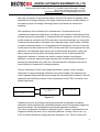
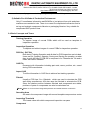
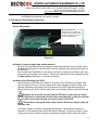
DEKTEC AUTOMATIC EQUIPMENT CO., LTD
ADD: C2 BUILDING,LINPOSHAN INDUSTRIAL ZONE,SHANGLIAO VILLAGE,SHAJIN TOWN,
BAO AN DISTRICT,SHEN ZHEN CITY, GUANG DONG PROVINCE, CHINA.
Tel:0755-61176799 Fax:0755-61176795
Http://www.deksmt.com E-mail:[email protected]
DEKTEC Automatic Optic Inspection
User Manual
Model OK-S350
2009 Edition
For Software 1.0 Version
1
DEKTEC AUTOMATIC EQUIPMENT CO., LTD
ADD: C2 BUILDING,LINPOSHAN INDUSTRIAL ZONE,SHANGLIAO VILLAGE,SHAJIN TOWN,
BAO AN DISTRICT,SHEN ZHEN CITY, GUANG DONG PROVINCE, CHINA.
Tel:0755-61176799 Fax:0755-61176795
Http://www.deksmt.com E-mail:[email protected]
Meaning Of Notices And Warnings On The Machine
This means important module, handled only by professionals.
This is a warning, means danger possible to cause wound or death
This is a warning, means no foreign object should enter when machine is
running, otherwise it could cause physical wound or machine damage.
40mm
PCB 限制高度
This is a warning, means height of object should be within the minimum
height to avoid both object and/or machine damage.
Thanks for purchasing and using our products.
Professional training is also provided if the product is purchased.
2
DEKTEC AUTOMATIC EQUIPMENT CO., LTD
ADD: C2 BUILDING,LINPOSHAN INDUSTRIAL ZONE,SHANGLIAO VILLAGE,SHAJIN TOWN,
BAO AN DISTRICT,SHEN ZHEN CITY, GUANG DONG PROVINCE, CHINA.
Tel:0755-61176799 Fax:0755-61176795
Http://www.deksmt.com E-mail:[email protected]
Important Information
Warranty
Copyright of this manual is reserved by the DEKTEC Automatic Equipment
Co., Ltd.
Any duplication or publication of this manual is prohibited without explicit
authorization from DEKTEC.
Guarantee & Responsibility
Information provided in this manual may change without prior notice from
the company. Direct or indirect loss due to modification of this manual will
not be answered for by DEKTEC.
DEKTEC is not responsible for any damage caused by user’ s negligence
such as, using inappropriate setting or placing the machine in an unsuitable
environment.
We try our best to provide correct information in the document. If you find
any detect, neglect or unjustifiable content in it, please inform us. We would
be very grateful for you help.
This operating manual has two aims:
To describe safety of this machine.
To introduce machine operation to the user.
3
DEKTEC AUTOMATIC EQUIPMENT CO., LTD
ADD: C2 BUILDING,LINPOSHAN INDUSTRIAL ZONE,SHANGLIAO VILLAGE,SHAJIN TOWN,
BAO AN DISTRICT,SHEN ZHEN CITY, GUANG DONG PROVINCE, CHINA.
Tel:0755-61176799 Fax:0755-61176795
Http://www.deksmt.com E-mail:[email protected]
Contents
Chapter 1 Safety
Chapter 2 Introduction to AOI Technology
2.1
Origin of AOI
2.2
Technical Theory of AOI
2.3
Technical Features of Otek AOI
2.4
Fundamental Concepts and Terms
Chapter 3 Introduction to Ok S350
3.1
Machine Components
3.2
Hardware Wire Connection Sketch Map
Chapter 4 Equipment installation and maintenance
4.1
Plane Adjustment and Supporting Pad Regulation
4.2
Camera Parameters
4.3
Servo Driver Parameters
4.4
Equipment Periodical Maintenance
4.5
Equipment Operating Specification
Chapter 5 System Settings
5.1
Camera calibration
5.2
Light luminance adjustment and Camera color calibration
5.3
Position restriction with software
Chapter 6 Introduction to Software Interface, Menu, & Toolbar
6.1
Running software
6.2
AOI Software Interface
6.3
Menu and Toolbar
Chapter 7 Training Operation Specification
7.1
Software Start
7.2
Training Flow
Chapter 8 Inspection Operation
Chapter 9 Inspection Report
Chapter 10 User Management
Chapter 11 Frequently Asked Questions (FAQ)
Accessory 1 Building CAD File
4
DEKTEC AUTOMATIC EQUIPMENT CO., LTD
ADD: C2 BUILDING,LINPOSHAN INDUSTRIAL ZONE,SHANGLIAO VILLAGE,SHAJIN TOWN,
BAO AN DISTRICT,SHEN ZHEN CITY, GUANG DONG PROVINCE, CHINA.
Tel:0755-61176799 Fax:0755-61176795
Http://www.deksmt.com E-mail:[email protected]
Chapter 1 Safety
1
1.1 General Statement
To use this machine safely and correctly, user should not only follow the preventive
safety measures specified in this manual, but also abide by general safety criterions.
Please read the danger warning and notice in this manual and/or on the machine
carefully.
1.2 Operator Qualification
Only those who are trained and are qualified operators can run, modify, maintain
and/or fix this machine.
Training levels are defined, as below:
■ Operator level
■ User level or Super user level
■ Maintenance man or Repairman level
1.3 Basic Safety Regulation
■ Do not use this machine in dusty place or in environment with inflammable gas.
■ Anyone mentioned here maintaining the machine (PPE) should follow description
from manufacturer.
1.4 Safety Standard
The safety of this machine is based on special industry standard (international law,
rules or standard).
1.5 Danger, Warning and Notice
Danger
This means death or grievous bodily harm will be caused if instruction is not
followed.
Warning
This means death or grievous bodily harm may be caused if instruction is not
followed.
Notice
This means bodily harm or equipment damage may be caused if instruction is
not followed. Also used to remind user or operator to avoid unsafe operation.
5
DEKTEC AUTOMATIC EQUIPMENT CO., LTD
ADD: C2 BUILDING,LINPOSHAN INDUSTRIAL ZONE,SHANGLIAO VILLAGE,SHAJIN TOWN,
BAO AN DISTRICT,SHEN ZHEN CITY, GUANG DONG PROVINCE, CHINA.
Tel:0755-61176799 Fax:0755-61176795
Http://www.deksmt.com E-mail:[email protected]
1.6 Responsibility
DEKTEC is not responsible for any damage caused by user’s operation of the
machine outside the instruction provided in this manual.
1.7 Where to put this manual
Keep this manual near to the machine, so user can read important information.
6
DEKTEC AUTOMATIC EQUIPMENT CO., LTD
ADD: C2 BUILDING,LINPOSHAN INDUSTRIAL ZONE,SHANGLIAO VILLAGE,SHAJIN TOWN,
BAO AN DISTRICT,SHEN ZHEN CITY, GUANG DONG PROVINCE, CHINA.
Tel:0755-61176799 Fax:0755-61176795
Http://www.deksmt.com E-mail:[email protected]
Chapter 2
2
Introduction to AOI Technology
The Automatic Optic Inspection(AOI)is mainly used to identify and recognize
component or soldering defects during Surface Mounting Technology (SMT)
manufacturing process.
2.1 Origin of AOI
These days, the function of electric products is more and more complicated, but the
size of these products is getting smaller and smaller. To fit with this trend, circuit
board, the core of modern electric products, are almost all manufactured through
Surface Mounted Technology(SMT). Circuit board produced though SMT is called
Printed Circuit Board(PCB),on which the density of parts/components are higher
and higher,and size is smaller and smaller. The 0402 components, even the 0201
components(0.50 mm×0.25 mm), are becoming new standard components in the
surface mounting industry. And distance between lead of integrate circuit (IC) is
reduced to 0.2 mm. This trend has brought the challenge to manual PCB inspection.
Automatic Optic Inspection(AOI)is a new optic- mechanic-electric incorporated high
technology, which appeared in this challenge. Though image capturing and analysis
on PCB, it’s possible to identify and recognize those components or attachment with
detect. Compared with manual inspection, AOI has higher speed, higher accuracy
and higher repeatability. Further more, it can also provide faster and more exact
feed back information for the manufacturing process, which can help to better
product quality, reduce the production cost, and accelerate production speed.
Usually, AOI equipment has two styles, the in-line model and desktop model. The
in-line pattern AOI can be put after the soldering machine to inspect the quality of
solder printing, after the chip mounter to inspect the quality of picking and placing,
and after the reflow soldering systems to inspect the quality of attachment. The
desk-top pattern AOI equipment needs an operator to put the PCB to the equipment
manually, and is usually used to inspect soldered PSB.
2.2 Technical theory of AOI
The image capturing of AOI can be divided into two styles, snapping style and
7
DEKTEC AUTOMATIC EQUIPMENT CO., LTD
ADD: C2 BUILDING,LINPOSHAN INDUSTRIAL ZONE,SHANGLIAO VILLAGE,SHAJIN TOWN,
BAO AN DISTRICT,SHEN ZHEN CITY, GUANG DONG PROVINCE, CHINA.
Tel:0755-61176799 Fax:0755-61176795
Http://www.deksmt.com E-mail:[email protected]
scanning style. In the snapping style, the camera moves step by step, and in every
step only one picture of a small area square on the PCB surface is captured. After
several times of image capturing, the image collecting process is finally finished. In
the scanning style, the image collecting process just needs one continuous
scanning.
AOI equipment can be divided into 2-dimensional, 2.5-dimensional and 3
–dimensional inspection equipments, according to the number of cameras and how
the light resource is positioned. In 2-dimensional AOI equipment, the axis of the lens
on the camera is vertical to the PCB, and there is no directional light, so only a little
3-dimentional information is included in the captured image, which makes it difficult
to inspect soldering detects. In 2.5-dementional AOI equipment, the axis of the lens
on the camera is also vertical to the PCB, but because light in the equipment is extra
directional, the captured image gains more 3-dimensional information, which can
help to inspect out more types of soldering detects. And in 3-demensional AOI
equipment, numbers of cameras are used to capture images from different
directions, and every captured image includes more 3-dimensional information. If
pictures are manipulated very well, the 3-dimensional AOI equipment can be the
most effective for inspection of soldering detects.
The key technology of AOI is the image identification system, which is mainly
composed of image-identifying arithmetic and normal images. By comparing the
to-be-inspected image and the normal image and calculating the correlation, the AOI
equipment can identify the status of the components on the PCB, as shown in the
sketch map below.
To-be-inspected image
Normal image
Image-identifying
arithmetic
Normal/abnormal
Figure 2.1
Presently, the most used image-identifying arithmetic is grayscale correlation
arithmetic, which quantifies the correlation between the to-be-inspected image and
the normal image, via calculating the normalized grayscale correlation.
The value of grayscale correlation is between 0 and 1, where 1 predicates the two
images are totally the same, but 0, absolutely different. Usually a limit is set, e.g.
0.65, to decide whether the image has been changed or not. Those of which the
8
DEKTEC AUTOMATIC EQUIPMENT CO., LTD
ADD: C2 BUILDING,LINPOSHAN INDUSTRIAL ZONE,SHANGLIAO VILLAGE,SHAJIN TOWN,
BAO AN DISTRICT,SHEN ZHEN CITY, GUANG DONG PROVINCE, CHINA.
Tel:0755-61176799 Fax:0755-61176795
Http://www.deksmt.com E-mail:[email protected]
grayscale correlation is higher than or equal to the threshold are to be considered
normal, but others of which the grayscale correlation is lower, abnormal.
The operating process of AOI equipment has two segments, the training process
and the inspection process. During the training process, the AOI control software
captures and collects the normal images and trains the code names, positions,
codes and polarities of the normal components on the normal PCBs, and finally an
inspecting program is built and saved. During the inspection process, the AOI
software captures and collects the images of to-be-inspected PCBs, identifies and
discriminates each components and the attachment according to the inspecting
program built in the training process, and finally records the inspection result and
reports it to the operator.
PCB inspection needs at least one training process to build the inspecting program,
so that the inspection process can be executed.
2.3 Technical features of Ok AOI
1) Strong Inspection Capability
Ok AOI adopts independently developed normalized color correlation arithmetic
instead of commonly used grayscale correlation arithmetic, utilizes the full RGB
color information to achieve better inspection accuracy and stability. Compared with
the grayscale correlation arithmetic, the color correlation arithmetic needs twice
more information data, which may lower the speed for twice of that of the former. But
with the MMX technology specially developed for multimedia application, the Ok
AOI can search and gain more information from images within the same or even
less time. Color correlation arithmetic can also identify color-marked components,
e.g. capacitors, which are but difficult for grayscale correlation arithmetic.
By setting the light, Ok AOI differentiates the images with excess or insufficient
attachment and normal image, and inspects and finds out soldering detect.
9
DEKTEC AUTOMATIC EQUIPMENT CO., LTD
ADD: C2 BUILDING,LINPOSHAN INDUSTRIAL ZONE,SHANGLIAO VILLAGE,SHAJIN TOWN,
BAO AN DISTRICT,SHEN ZHEN CITY, GUANG DONG PROVINCE, CHINA.
Tel:0755-61176799 Fax:0755-61176795
Http://www.deksmt.com E-mail:[email protected]
Soldering inspecting arithmetic of OK AOI has the features of high inspection
veracity and low inspecting mistaking ratio.
Attachment inspecting arithmetic of Ok AO I relies far less on the absolute position
of attachment, which betters its inspection effect under the same even lower
positioning precision, compared with other generic products.
2) Strong Self-training Ability
Any size or type of component can be trained, by drawing a box surrounding the
component, and no special treatment is needed. Ok AOI will finish feature
extractions, algorithm selections, and parameter settings automatically. Attachment
inspection for resistors, capacitors and lead inspection for IC components are
almost self- trained, relieving programmers of all the tedious work. Programming can
usually be completed in less than 0.5 hours. Inspection arithmetic of Ok AOI is
easy for operation, no parameter adjustment and/or special debugging process is
needed.
Ok AOI software keeps training new templates during inspection, and boards with
wrong components can be used during the training process, so no special “Golden
Board” is required for initial programming. During the training process, Ok AOI will
inspect the PCBs and find out detects on the boards,which can help to debug the
new boards in product line.
3) Strong Information Collecting and Sharing Ability
Ok AOI saves the detect information found out during the inspection process into a
database. With Ok SPC Module of the software, managers and technicians can
accurately train the real-time manufacturing condition in MST product line, and
estimate and take action on any kind of abnormal phenomenon.
Using the Ok maintaining workstation, the maintenance man can quickly find out
the position information about a wrong PCB within its image, by scanning the serial
number on the barcode with barcode-scanner.
4) Simple Brief Software Interface
Simple and brief software interface and detailed help files facilitate users’ operation
of Ok AOI during the inspection proce ss. Familiar windows drag and drop user
interfaces greatly reduce training time. Operator trainings are generally less than 4
10
DEKTEC AUTOMATIC EQUIPMENT CO., LTD
ADD: C2 BUILDING,LINPOSHAN INDUSTRIAL ZONE,SHANGLIAO VILLAGE,SHAJIN TOWN,
BAO AN DISTRICT,SHEN ZHEN CITY, GUANG DONG PROVINCE, CHINA.
Tel:0755-61176799 Fax:0755-61176795
Http://www.deksmt.com E-mail:[email protected]
hours, and programmer trainings are generally less than 8 days.
5) Suitable For All Kinds of Production Environment
Only XY coordinates information and BOM file or just printout from pick and place
machines are needed to train. There is no need for complicated conversion and to
set up and maintain components libraries or packaging libraries. Very suitable for
complicated SMT product lines.
2.4 Basic Concepts and Terms
Training Operation
To capture image of normal PSBs which will be used as template in
inspection operation.
Inspection Operation
To capture and collect images of current PSBs for inspection operation.
PCB file ( .DAT file)
Built during Training Operation and all data for PCB inspection are included.
Users can do Creating, Opening, Saving and Saving As operation as what
they do with MS Word. PCB file is composed of a “filename.dat” file and a
folder with name “filename”.
CAD File
Document with information including part code, name, position, etc., saved
during PCB manufacture.
Import CAD
To utilize information in CAD files to achieve fast training operation.
Fiducial
Usually a PCB has 2 to 4 fiducials,which are used to orientate the PCB
well during manufacture. AOI also uses the fiducials to orientate the PCB.
Since the relative position between fiducials and components are stable,
positions of parts or components can also be calculated out.
【Notes】Better to choose those image with particular and stable features as fiducials.
Searching Area
An area in the component image with normal template component as center
Inspecting Threshold
The lowest value with which component inspection can pass.
Component
11
DEKTEC AUTOMATIC EQUIPMENT CO., LTD
ADD: C2 BUILDING,LINPOSHAN INDUSTRIAL ZONE,SHANGLIAO VILLAGE,SHAJIN TOWN,
BAO AN DISTRICT,SHEN ZHEN CITY, GUANG DONG PROVINCE, CHINA.
Tel:0755-61176799 Fax:0755-61176795
Http://www.deksmt.com E-mail:[email protected]
Electronic units on PCBs.
Part
Components of the same class.
Template
A model built in training process.
Component Template
An image template of a component built in training process.
Part Template
Template of components in the same class.
Administrator
User having the right of training, inspecting, and adding and deleting users.
Operator:
User having only inspecting right.
12
DEKTEC AUTOMATIC EQUIPMENT CO., LTD
ADD: C2 BUILDING,LINPOSHAN INDUSTRIAL ZONE,SHANGLIAO VILLAGE,SHAJIN TOWN,
BAO AN DISTRICT,SHEN ZHEN CITY, GUANG DONG PROVINCE, CHINA.
Tel:0755-61176799 Fax:0755-61176795
Http://www.deksmt.com E-mail:[email protected]
3
Chapter 2 Instroduction to Ok S350
3.1 Machine Components
1) Main body of AOI:
■ XY-Axis Servo Driver System: Adopt imported servo motor and controller
■ Motion Control System
■ CMOS/CCD imaging system with 3 million pixels
■ Annular LED light resource
■ Host Supporting Frame
2) Image Processing Center, including Host computer, Monitor, Keyboard, Mouse
3) Optional Assemblies:Out Printing Unit(for inspection result printing), Maintaining
Workstation
3.2 Hardware Connection Sketch Map
■ How to Connect
Figure 3-1
13
DEKTEC AUTOMATIC EQUIPMENT CO., LTD
ADD: C2 BUILDING,LINPOSHAN INDUSTRIAL ZONE,SHANGLIAO VILLAGE,SHAJIN TOWN,
BAO AN DISTRICT,SHEN ZHEN CITY, GUANG DONG PROVINCE, CHINA.
Tel:0755-61176799 Fax:0755-61176795
Http://www.deksmt.com E-mail:[email protected]
Figure 3-2
Figure 3-3
14
DEKTEC AUTOMATIC EQUIPMENT CO., LTD
ADD: C2 BUILDING,LINPOSHAN INDUSTRIAL ZONE,SHANGLIAO VILLAGE,SHAJIN TOWN,
BAO AN DISTRICT,SHEN ZHEN CITY, GUANG DONG PROVINCE, CHINA.
Tel:0755-61176799 Fax:0755-61176795
Http://www.deksmt.com E-mail:[email protected]
Chapter 4 Equipment Installation and
Maintenance
4
4.1 Plane Adjustment and Supporting Pad Regulation
When the machine arrives, user can set down the supporting pads and with the help
of a gradienter (or other tools) regulate the supporting pads till the station is on a flat
surface, and decrease its libration. (A proper plane adjustment can allow the
equipment perform well with low noise and a long life.)
4.2 Camera Parameters
Warning: Precious module, setting unavailable for laypeople. Unsuitable
Setting may cause fatal detect to the AOI.
Other parameters can be set through the software.
4.3 Servo Driver Parameters
Setting unavailable for laypeople. Unsuitable setting may cause fatal detect to the
servo, and damage the machine or cause bodily harm to the user. If parameter
setting is needed, please contact maintenance man with the G-First.
4.4 Equipment Periodical Maintenance
To keep the equipment running correctly with a long life, please operate as
described below:
■ Shut off the power supply of AOI and the computer if the machine won’t be
used in more than 2 hours.
■ Clean the dust on the equipment with dust collector or dry cloth everyday
half month.
Notice:Blower for dust cleaning is strictly forbidden being used here, since it
easily brings dust into the machine, which clings to the ball screw and slider or
lens, and may stop the machine from running correctly.
■ Lubricate the ball screw and slider and supporting parts with lube or lubricant
once every 3 month, which can reduce surface friction of ball screw and slider,
and keep sound lower while the machine is running, and prolong the life of ball
screw and slider.
■ Clean the dust filter of the computer once every 3 months.
15
DEKTEC AUTOMATIC EQUIPMENT CO., LTD
ADD: C2 BUILDING,LINPOSHAN INDUSTRIAL ZONE,SHANGLIAO VILLAGE,SHAJIN TOWN,
BAO AN DISTRICT,SHEN ZHEN CITY, GUANG DONG PROVINCE, CHINA.
Tel:0755-61176799 Fax:0755-61176795
Http://www.deksmt.com E-mail:[email protected]
■ Calibrate the camera once every 3 month.
4.5 Equipment Operating Specification
■ Set PCB position
Put the PCB into the
left-bottom corner. Adjust the
shaft to lock the PCB properly.
Confirm it’s properly set, and
screw the bolts tightly.
Figure 4-1
■ Switch on power supply and restart machine
Be sure all connecting wires are properly connected and the circuit is linked, press
the Power pushbutton on the AOI host, and the indicator light will light and the host
will start up.
Once it has been switched on, and there is a need to restart the machine, user can
just switch off the power and restart it. When the machine has been restarted, press
the Reposition pushbutton to reset the machine.
■ Inserting and Removing the PCB
When placing a PCB, take the middle of one side of the PCB with one hand, and
with an angle of 45º, put it into the stage which was adjusted in the first step, then
arrange it parallel to the stage. Avoid contact with the PCB right after inserting it.
When removing the PCB, avoid contact with it immediately after successfully taking
it out.
Because the machine can self-detect PCB which is put onto the stage,
and the PCB will be conveyed into the inside automatically in about 2 seconds,
be sure that it won’t take to long to insert or remove the PCB.
This product is equipped with safety curtain, which can help to keep the
operator safe.
The safety curtain covers the whole operating station, which allows operator to
operate on PCB setting. After the PCB setting is finished, it will give a signal, which
notices the control module to start the inspection program after a short time delay,
16
DEKTEC AUTOMATIC EQUIPMENT CO., LTD
ADD: C2 BUILDING,LINPOSHAN INDUSTRIAL ZONE,SHANGLIAO VILLAGE,SHAJIN TOWN,
BAO AN DISTRICT,SHEN ZHEN CITY, GUANG DONG PROVINCE, CHINA.
Tel:0755-61176799 Fax:0755-61176795
Http://www.deksmt.com E-mail:[email protected]
and now everything is ready. If any unexpected object (e.g. hand) enters into the
inspecting area, the safety curtain will give signal to the control module to stop
moving parts, so that the machine is protected.
When restarting the machine, user should push the Reset button to reset the
machine to the original position and restart the inspection process.
■ Reposition
Generally, the machine will detect the PCB on the stage. If the PCB is not
automatically inserted, just push the Reposition pushbutton on the AOI host.
■ Emergency Stop Button
When meeting any emergency,please immediately push the Emergency button in the front of
the AOI host. If wanting to cancel the emergency, just unscrew the button out, and push the
Reposition pushbutton.
17
DEKTEC AUTOMATIC EQUIPMENT CO., LTD
ADD: C2 BUILDING,LINPOSHAN INDUSTRIAL ZONE,SHANGLIAO VILLAGE,SHAJIN TOWN,
BAO AN DISTRICT,SHEN ZHEN CITY, GUANG DONG PROVINCE, CHINA.
Tel:0755-61176799 Fax:0755-61176795
Http://www.deksmt.com E-mail:[email protected]
Chapter 5
System Settings
5
5.1 Camera calibration
Camera calibration can help to test the exact resolving power and fixing angle. The camera of
the host has the resolving power of 20 micron/pixel, and the fixing angle is zero. For some
artificial reason, position of the camera may be changed slightly. Proper calibration can help to
keep the camera capturing images correctly.
Details are below.
1) Place and clamp the PCB onto the conveyor.
2) Run the software, make a map, and double click a point in the map, the camera will be
moved to that pace. As shown in Figure 5-1.
Figure 5-1
3) Click Train in the Control Panel (as shown in Figure 5-2), the page will be switched to
another one (as shown in Figure 5-3).
18
DEKTEC AUTOMATIC EQUIPMENT CO., LTD
ADD: C2 BUILDING,LINPOSHAN INDUSTRIAL ZONE,SHANGLIAO VILLAGE,SHAJIN TOWN,
BAO AN DISTRICT,SHEN ZHEN CITY, GUANG DONG PROVINCE, CHINA.
Tel:0755-61176799 Fax:0755-61176795
Http://www.deksmt.com E-mail:[email protected]
Figure 5-2
Figure 5-3
4) In this page, click Fidu, and a blue frame will appear, and a dialog will ask you to train the
first ficucial. Choose an unique-featured area on the top-left corner of the board, and confirm it.
Then train the second fiducial on the bottom-right corner in the same way.
5) Click NewComp, and a blue frame will appear, Choose an unique-featured area on the
top-left corner of the image, and adjust the blue frame to match the area. As shown in Figure
5-4.
19
DEKTEC AUTOMATIC EQUIPMENT CO., LTD
ADD: C2 BUILDING,LINPOSHAN INDUSTRIAL ZONE,SHANGLIAO VILLAGE,SHAJIN TOWN,
BAO AN DISTRICT,SHEN ZHEN CITY, GUANG DONG PROVINCE, CHINA.
Tel:0755-61176799 Fax:0755-61176795
Http://www.deksmt.com E-mail:[email protected]
图 5-4
Press Enter, a dialog will pop up. Set the name of the component to calibrator, the
threshold to 850, and uncheck the 自检焊盘. As shown in Figure 5-5.
Figure 5-5
And click Ok.
6) Choose Calibrate in the menu Train, as shown in Figure 5-6.
20
DEKTEC AUTOMATIC EQUIPMENT CO., LTD
ADD: C2 BUILDING,LINPOSHAN INDUSTRIAL ZONE,SHANGLIAO VILLAGE,SHAJIN TOWN,
BAO AN DISTRICT,SHEN ZHEN CITY, GUANG DONG PROVINCE, CHINA.
Tel:0755-61176799 Fax:0755-61176795
Http://www.deksmt.com E-mail:[email protected]
Figure 5-6
Click Ok/Yes, after a few minutes a dialog will pop up, showing the results of the calibration. As
shown in Figure 5-7.
Figure 5-7
Now, the calibration is finished.
If another dialog pop up in stead of result showing dialog, as shown in Figure 5-8,you need to
check if the name was set to calibrator, you need to delete the component and operate the
steps above again.
Figure 5-8
5.2 Light Luminance Adjusting and Camera Color Calibration
21
DEKTEC AUTOMATIC EQUIPMENT CO., LTD
ADD: C2 BUILDING,LINPOSHAN INDUSTRIAL ZONE,SHANGLIAO VILLAGE,SHAJIN TOWN,
BAO AN DISTRICT,SHEN ZHEN CITY, GUANG DONG PROVINCE, CHINA.
Tel:0755-61176799 Fax:0755-61176795
Http://www.deksmt.com E-mail:[email protected]
Light luminance adjusting can uniform the light sensitivity of camera. Camera color calibration
can reduce the color difference between the real objects and captured images. Proper light
luminance adjusting and camera color calibration is conditioned for the machine to inspect
PCB correctly and stably.
Detailed steps are below:
■ Choose Train → SetStage from the menu
■ Choose Camera, and set parameters as shown in Figure 5-9.
System settings below are commended:User can set camera parameters here, which includes
Exposure, Gain, and White Balance.
After setting the parameters, click Apply to confirm the choices.
User can refresh the images by right clicking and dragging the image with right button down.
Figure 5-9
【Notes】Handled only by professionals. Light luminance and camera color are adjusted and calibrated
before leaving factory, and settings in this manual are strongly commended.
5.3 Control
Position Restriction with Software is designed for the purpose of protecting electromotor, and
is the last protection method for the electromotor after servo position limitation and movement
position limitation. It can help to avoid machine damage when motor exceeding mechanical
range during running.
Detailed steps are below:
Select Train → SetStage → Motion from the menu.
Cue: The value has direct ratio to speed of the machine.
22
DEKTEC AUTOMATIC EQUIPMENT CO., LTD
ADD: C2 BUILDING,LINPOSHAN INDUSTRIAL ZONE,SHANGLIAO VILLAGE,SHAJIN TOWN,
BAO AN DISTRICT,SHEN ZHEN CITY, GUANG DONG PROVINCE, CHINA.
Tel:0755-61176799 Fax:0755-61176795
Http://www.deksmt.com E-mail:[email protected]
图 5-10
【Notes】Unavailable for layman. Restriction by software is all set before leaving factory;
settings in this manual are strongly commended.
1) X_con_speed: original conveyor speed of X dimension, um/s.
Y_con_speed: original conveyor speed of Y dimension, um/s.
X_fast_speed: max conveyor speed of X dimension, um/s.
Y_fast_speed: max conveyor speed of Y dimension, um/s.
X_accel_speed:acceleration of X dimension, um/s^2.
Y_accel_speed:acceleration of Y dimension, um/s^2.
X_s_speed:S acceleration of X dimension, um/s^2.
Y_s_speed:S acceleration of X dimension, um/s^2.
2) Trigger Delay: Delay time after the light is on.
Trigger Time: Lasting time of the trigger.
【Notes】Handled only by professionals.
5.4 Status
23
DEKTEC AUTOMATIC EQUIPMENT CO., LTD
ADD: C2 BUILDING,LINPOSHAN INDUSTRIAL ZONE,SHANGLIAO VILLAGE,SHAJIN TOWN,
BAO AN DISTRICT,SHEN ZHEN CITY, GUANG DONG PROVINCE, CHINA.
Tel:0755-61176799 Fax:0755-61176795
Http://www.deksmt.com E-mail:[email protected]
Figure 5-11
In this page, the settings usually are stable, so no need to change.
Current Psition: the poison of the conveyor.
Machine: the status of the hardware.
Stage: self-conveyed or not.。
Board: during inspection, if PCB is detected on the conveyor.
Pixel X, Pixel Y :the result of calibration, um/pixel.
5.5 Settings
Figure 5-12
Parameters
prompt_serial_num: to input serials or not.
printer_conrol: to print data with printer or not.
need_optimize_path: to use optimized path or not.
report: to save the inspecting result to database or not.
skip_board: no inspection on a part of the paneled board, or to set the max NG number, if
the result number is bigger than it, the inspection is failed.
component_inspection: to inspect components or not.
solder_inspection: to inspect solders or not.
24
DEKTEC AUTOMATIC EQUIPMENT CO., LTD
ADD: C2 BUILDING,LINPOSHAN INDUSTRIAL ZONE,SHANGLIAO VILLAGE,SHAJIN TOWN,
BAO AN DISTRICT,SHEN ZHEN CITY, GUANG DONG PROVINCE, CHINA.
Tel:0755-61176799 Fax:0755-61176795
Http://www.deksmt.com E-mail:[email protected]
lead_inspection: to inspect leads or not.
solder_auto_inspection: 是否检测学习为自检焊盘的器件焊盘。
need_update_bright_constract: to adjust brightness and contract of
or not.
english: 1 English, 0 Chinese.
B Engine:Engine settings.
C Other
component image
Figure 5-13
super: 1 super user, 0 no super user.
max_failure: max NG number
auto_test_mode: 1 demo mode, 0 no demo mode.
camera_width: image width, pixels.
camera_height: image height, pixels.
camera_type: Camera type.
D Origins
Figure 5-14
25
DEKTEC AUTOMATIC EQUIPMENT CO., LTD
ADD: C2 BUILDING,LINPOSHAN INDUSTRIAL ZONE,SHANGLIAO VILLAGE,SHAJIN TOWN,
BAO AN DISTRICT,SHEN ZHEN CITY, GUANG DONG PROVINCE, CHINA.
Tel:0755-61176799 Fax:0755-61176795
Http://www.deksmt.com E-mail:[email protected]
x_origin: Original Y value, changing according to scanning area, no need to modify, unit: mm.
y_origin: Original X value.
5.6 Other
图 5-15
A Parameter settings
roi_color: color of common component frame.
verify_col: frame color of under-verified component.
failed_roi: frame color of defect component.
search_ro: frame color of searching field.
lead_roi_l: frame color of leads.
B settings
pcb_name: board name
line_number: manufacture line number
26
DEKTEC AUTOMATIC EQUIPMENT CO., LTD
ADD: C2 BUILDING,LINPOSHAN INDUSTRIAL ZONE,SHANGLIAO VILLAGE,SHAJIN TOWN,
BAO AN DISTRICT,SHEN ZHEN CITY, GUANG DONG PROVINCE, CHINA.
Tel:0755-61176799 Fax:0755-61176795
Http://www.deksmt.com E-mail:[email protected]
6
Chapter 6 Instruction of Software Interface,
Menu, & Toolbar
6.1 Running Software
Run AOI.EXE to start AOI software system.
6.2 AOI Software Interface
The software main interface is composed of Menu, Toolbar, Image Window, and
the Zoom-out Window, Component List Window and Status Bar. (As Shown in
Figure 6-1)
Figure 6-1 Software Main Interface
6.3 Menu and Toolbar
There are eight menus in the Menu Bar, including File, Train, Inspect, Report, Picture, User
Manager, Windows and Help.
Under the Menu Bar is a toolbar, composed of Load, Save, Inspect, Stop, Align, Preview, Area,
27
DEKTEC AUTOMATIC EQUIPMENT CO., LTD
ADD: C2 BUILDING,LINPOSHAN INDUSTRIAL ZONE,SHANGLIAO VILLAGE,SHAJIN TOWN,
BAO AN DISTRICT,SHEN ZHEN CITY, GUANG DONG PROVINCE, CHINA.
Tel:0755-61176799 Fax:0755-61176795
Http://www.deksmt.com E-mail:[email protected]
Scan, Ficucial, Import, Test, New, Show, Guide, Panel, Camera, Board, Reset, In, and Out.
Detailed functions and usage are below.
Figure 6-2
6.3.1 Menu Bar
1) File
Load Board… : To open a trained PCB file for next inspection
Save Board… : To save the training finished PCB file
Save As… : To save the current trained PCB file with another
name Relogin: To log in with another user name with different
authority
Exit:To exit and close the software
2)Train
CreateBoard: To train a PCB file with a wizard
Show: There are three types of display mode, no displaying,
displaying component, displaying the searching area. The default
is displaying component.
Create New Board:To train a PCB file with a wizard
Transfer New Board: To convert DAT file between 2 machines
New Component:To train a new component in the current PCB
image
Confirm Component:To confirm the current operation
Train Fiducial: To set 2 flags in the current PCB image as anchor
point of logical coordinate
Import CAD:To import a CAD file to train a PCB file
Export CAD:To export a CAD file
Train Barcode:To train the barcode on the PCB as a component
Train Panel Manual:To train a combined PCB by training and
copying a sub-board in the PCB
LoadImageList: To load a list of images
SaveImageList: To save the current image list
Load Image: To load an image from hardware
Save Image: To save the image currently captured by the camera
Set Stage:To manually adjust parameters of X and/or Y axis
including Motor Parameters、Camera Parameters, status
Calibrate:To calibrate the machine
OnLive: To start camera mode and capture image
OnImage:To turn off the camera mode
Switch:A->B:To exchange A and B side of a board
28
DEKTEC AUTOMATIC EQUIPMENT CO., LTD
ADD: C2 BUILDING,LINPOSHAN INDUSTRIAL ZONE,SHANGLIAO VILLAGE,SHAJIN TOWN,
BAO AN DISTRICT,SHEN ZHEN CITY, GUANG DONG PROVINCE, CHINA.
Tel:0755-61176799 Fax:0755-61176795
Http://www.deksmt.com E-mail:[email protected]
3)Inspect
Stop Inspect Board: To stop the current self-recycling Inspection
Auto Inspection: To start the self-recycling inspection
Set Search Margin: To set the inspecting area of the component
Set Attachment Search Margin: To set the inspecting area ofe
attachments
Set Shift Tolerance: To set shift tolerance
Set Pass Score:To set the lowest value for component inspection
to pass
4)Report
Report Last Result: To start the analyzing software for inspection
result analysis
5)Picture
FullBoard: To resize the image to fit with window to explore
ZoomIn: To zoom in the current PCB image
ZoomOut: To zoom out the current PCB image
ShowActualSize: To display image with its actual size
6)User Manage
UserManager: To popup a edit dialog to manage users using the
machine and their operating right.
7)Windows:
Click on the items can display and/or hide the relevant window.
8)Help
Help: To display the help file
CorpWeb :To visit the website of GFirst
Support : To get technical support information
About: To display brief information about Otek AOI and software
version
Debug:Only used for developers.
6.3.2 Control Panel
There are mainly three pages in the Control Panel. Pages of Control Panel and tools in
the pages change according to user’s operations.
1)Control Page
Reset: The same with ShowActualSize in the Picture menu.
Out: The same with ZoomOut in the Picture menu.
29
DEKTEC AUTOMATIC EQUIPMENT CO., LTD
ADD: C2 BUILDING,LINPOSHAN INDUSTRIAL ZONE,SHANGLIAO VILLAGE,SHAJIN TOWN,
BAO AN DISTRICT,SHEN ZHEN CITY, GUANG DONG PROVINCE, CHINA.
Tel:0755-61176799 Fax:0755-61176795
Http://www.deksmt.com E-mail:[email protected]
In: The same with ZoomIn in the Picture menu.
Show: There are three types of display mode, no displaying, displaying component,
displaying the searching area. The default is displaying component.
Display: to display all components.
Hide: to hide all components.
Confirm: to confirm the last operation.
Cancel: to cancel the last operation.
Load: To load a PCB image
Map: to make a map for a board.
Live: the same to OnLive in menu Train.
DeleteA: to delete all components.
Figure 6-3
StageIn: to move the conveyor in.
StageOut: to move the conveyor out.
Save: The same with SaveBoardProgramFile in File menu.
|<Inspect>|: to switch to the Inspect page.
|<Train>|: to switch to the Train page.
2) Inspect Page
Figure 6-4
Reset: The same as ShowActualSize in the Picture menu.
Out: The same with ZoomOut in the Picture menu.
In: The same with ZoomIn in the Picture menu.
Show: There are three types of display mode, no displaying, displaying component,
30
DEKTEC AUTOMATIC EQUIPMENT CO., LTD
ADD: C2 BUILDING,LINPOSHAN INDUSTRIAL ZONE,SHANGLIAO VILLAGE,SHAJIN TOWN,
BAO AN DISTRICT,SHEN ZHEN CITY, GUANG DONG PROVINCE, CHINA.
Tel:0755-61176799 Fax:0755-61176795
Http://www.deksmt.com E-mail:[email protected]
displaying the searching area. The default is displaying component.
NewComp: To create a new component.
Board: To train a board with Guide.
CAD: To import a CAD file to train a PCB file.
Fidu: To set four fiducials for the current PCB.
Align: To automatically search for fiducials.
Panel: To combine a board to a combined PCB.
Rotate: To rotate the current frame.
Save: The same as SaveAs in menu File.
|<Back>|:To switch the page back to Control page.
3) Inspect Page
Figure 6-3
Reset: The same as ShowActualSize in the Picture menu.
Out: The same with ZoomOut in the Picture menu.
In: The same with ZoomIn in the Picture menu.
Show: There are three types of display mode, no displaying, displaying component,
displaying the searching area. The default is displaying component.
Align Board: Align the PCB with fiducials.
Auto Inspect: to inspect a board.
A->B: To exchange A and B side of a board.
Save: The same as SaveAs in menu File.
|<Back>|:To switch the page back to Control page.
6.3.3 Right Mouse Button
1) If the machine is inspecting board, by right click and drag on the main image user can
control to move the camera to a new place.
2) If it is under inspection, by right click the frames of component, attachment or leads,
user can activate them, then tools in the Control Panel will also change.
31
DEKTEC AUTOMATIC EQUIPMENT CO., LTD
ADD: C2 BUILDING,LINPOSHAN INDUSTRIAL ZONE,SHANGLIAO VILLAGE,SHAJIN TOWN,
BAO AN DISTRICT,SHEN ZHEN CITY, GUANG DONG PROVINCE, CHINA.
Tel:0755-61176799 Fax:0755-61176795
Http://www.deksmt.com E-mail:[email protected]
7
Chapter 7 Training Operation Specification
7.1 Software Start
To start the software, double click the AOI icon on the desktop or select Start --> Program -->
Otek AOI --> AOI. When the AOI software is started, an User Login dialog will popup, as
shown in Figure 7-1. Enter user name and password, and click Ok to confirm, or Cancel to
quit.
7.2 Train Flow
7.2.1 Brief Introduction
When user logs on with administrator status, he can use the Create Board to create a PCB file
according to its clue.
Click the Guide on the Toolbar (or select Create Board in Train menu), a wizard dialog will
popup, as shown in Figure 7-2.1)
Step 1: Make Map
Click |<Train>| in the Control Panel, a dialog will pop up, user can create a PCB file according
to its clue.
As shown in Figure 7-1.
Figure 7-1
Click Yes.
Double click in the dialog,move the camera to the top-left of the board.
图 7-2
With the left mouse button, drag the blue frame to the top-left corner of the board and in
the dialog click Yes.
32
DEKTEC AUTOMATIC EQUIPMENT CO., LTD
ADD: C2 BUILDING,LINPOSHAN INDUSTRIAL ZONE,SHANGLIAO VILLAGE,SHAJIN TOWN,
BAO AN DISTRICT,SHEN ZHEN CITY, GUANG DONG PROVINCE, CHINA.
Tel:0755-61176799 Fax:0755-61176795
Http://www.deksmt.com E-mail:[email protected]
Figure7-3
Then choose the next corner the same way.
And the machine will scan the board.
图 7-4
Step 2: Train Fiducial
After finishing capturing images, the software will ask user to set two fiducials for the PCB, as
shown in Figure 7-5). Here user needs to use both the top and side light, and adjust the
selecting frame to set a fiducial, click Ok or press Enter key on the keyboard, and the first
anchor point will be set. Then with the same operation, another anchor points can be set.
Figure 7-5
Figure 7-6
33
DEKTEC AUTOMATIC EQUIPMENT CO., LTD
ADD: C2 BUILDING,LINPOSHAN INDUSTRIAL ZONE,SHANGLIAO VILLAGE,SHAJIN TOWN,
BAO AN DISTRICT,SHEN ZHEN CITY, GUANG DONG PROVINCE, CHINA.
Tel:0755-61176799 Fax:0755-61176795
Http://www.deksmt.com E-mail:[email protected]
【Points】The fiducials are usually areas in the image with unique feature, in other words,
there should be no similar image area near the selected point.(e.g. designator silk-screen)
Step 3:Import CAD file And Training Components
After the 2 fiducials are set, the system will ask to import CAD file. (As shown in Figure7-7)
Click Yes.
Figure7-7
Select CAD file of the current PCB, and click Open
Figure 7-8
Step 4: Train 4 Components
A dialog will popup (as shown in Figure7-9) asking user to set and confirm positions of four
components in the image
Figure7-9
The four components are particularly selected from the CAD file, which are at the four corners
in the PCB. And in principle, the four components should have the shortest distance to the four
vertexes on the PCB.
34
DEKTEC AUTOMATIC EQUIPMENT CO., LTD
ADD: C2 BUILDING,LINPOSHAN INDUSTRIAL ZONE,SHANGLIAO VILLAGE,SHAJIN TOWN,
BAO AN DISTRICT,SHEN ZHEN CITY, GUANG DONG PROVINCE, CHINA.
Tel:0755-61176799 Fax:0755-61176795
Http://www.deksmt.com E-mail:[email protected]
Figure 7-10
【Point】
a) Generally, components are always with a white-bordered frame of silk-screen. When
positioning a component, adjust the selecting frame to fit the white-bordered frame, and the
component will be positioned correctly.
b) The four components should not be too big, if the component automatically given by system
can not fit the request, just click Skip, and the system will automatically select another part
nearby and wait for user to confirm.
c) When adjusting the size of the selecting frame, please take the image in the Actual Image
Window as reference at the right-top corner.
After the two steps above, system should begin to guide user to train components on the PCB
according to the order in the CAD file.
Figure 7-11
Step 5: Train Components
After the two steps above, system should begin to guide user to train components on the PCB
according to the order in the CAD file. As shown in Figure 7-12.
35
DEKTEC AUTOMATIC EQUIPMENT CO., LTD
ADD: C2 BUILDING,LINPOSHAN INDUSTRIAL ZONE,SHANGLIAO VILLAGE,SHAJIN TOWN,
BAO AN DISTRICT,SHEN ZHEN CITY, GUANG DONG PROVINCE, CHINA.
Tel:0755-61176799 Fax:0755-61176795
Http://www.deksmt.com E-mail:[email protected]
Figure 7-12
A green-bordered frame will automatically appear, surrounding the current component to
train. Adjust the size of the frame using mouse or keyboard and click Ok/Yes in the dialog or
just press Enter key on the keyboard to finish current component training.
As shown in Figure 7-13
Figure 7-13
If the current component is incorrect and not fit to be made a template, just click Wrong,and
the next time the same component is encountered during inspection, system will inform user to
choose whether to re-train it. Wrong component is marked with red frame.
If user come across components that don’t need to be inspected or should not have existed,
just click Skip to ignore the current component. (But for those missed components user should
click Wrong or use shortcut key Ctrl + D)
User can click Cancel to cancel importing current CAD file.
【Point】
1) This software has self-training capability, when finishing training a component, the software
will automatically train other homotype components on the current PCB. If self-training cannot
achieve previously set conditions, the software will mark the component with a pink frame (As
shown in Figure 7-14), and suggest user to adjust the selecting frame manually to achieve the
best conditions.
2) If the component is color-correlated, user can choose Auto checkbox, and select Color; if it
is characters, select Char.
3) If the component has polarity, check the Polarity checkbox.
36
DEKTEC AUTOMATIC EQUIPMENT CO., LTD
ADD: C2 BUILDING,LINPOSHAN INDUSTRIAL ZONE,SHANGLIAO VILLAGE,SHAJIN TOWN,
BAO AN DISTRICT,SHEN ZHEN CITY, GUANG DONG PROVINCE, CHINA.
Tel:0755-61176799 Fax:0755-61176795
Http://www.deksmt.com E-mail:[email protected]
Figure 7-14
After all components the same type are trained, system will inform user to train the next
component according to the order in the CAD file. Follow operation described above to train
other homotype components on the PCB.
After finishing all trainings, system will popup an information dialog showing information of
imported components. (As shown in Figure 7-15)
Figure 7-15
Step 6: Train attachment
Figure 7-16
Click Yes.
Green-bordered frame will appear and surround attachments of the component to train. (As
shown in Figure 7-17) Use mouse or direction keys to move the frame to proper position,
adjust the size of the frame with mouse or Ctrl + Direction. The Right and Left keys can be
used to adjust the width of the frame, and Up and Down keys, the height. After finishing
37
DEKTEC AUTOMATIC EQUIPMENT CO., LTD
ADD: C2 BUILDING,LINPOSHAN INDUSTRIAL ZONE,SHANGLIAO VILLAGE,SHAJIN TOWN,
BAO AN DISTRICT,SHEN ZHEN CITY, GUANG DONG PROVINCE, CHINA.
Tel:0755-61176799 Fax:0755-61176795
Http://www.deksmt.com E-mail:[email protected]
operation above, click Train to finish training the attachment and go to the next, and if user
thinks there is something wrong with the attachment, just click Detect, and system will inform
to retrain it during next PCB inspection. If the default orientation of attachment by the system is
incorrect, click Rotate to readjust it.
Figure 7-17
Cue:
1) It is better to have shadow of solder included in the frame, this can lead to a better training
effect.
2) If attachment automatic training is enabled when user creating CAD file with CAD Generator,
software will automatically finish training attachment(s) of the component when training the
component. If not, software will inform user to train attachment(s). (Attachments of IC are
not included here.)
3) To achieve a better inspecting effect in training attachment, selected area should include
bright and dark parts of the attachment(s).
4) To achieve a better inspection effect in training IC attachments, the selected area should be
longer than the length of the attachments, and it is better to set 1/2 of the distance between
attachments longer as shown in Figure 7-18.
5) For those components with big size, you need to divide them into several ICs to train, after
training components according to CAD data.
After finishing training attachments on one side, system will draw a new green broken-line
bordered frame symmetrical on another side of the component. With the same principle, adjust
the position with mouse or direction keys, then click Train to finish training the attachment.
Click Complete to finish training attachments.
38
DEKTEC AUTOMATIC EQUIPMENT CO., LTD
ADD: C2 BUILDING,LINPOSHAN INDUSTRIAL ZONE,SHANGLIAO VILLAGE,SHAJIN TOWN,
BAO AN DISTRICT,SHEN ZHEN CITY, GUANG DONG PROVINCE, CHINA.
Tel:0755-61176799 Fax:0755-61176795
Http://www.deksmt.com E-mail:[email protected]
Figure 7-18
The software has the capability of self-training, after finishing training attachment(s), it will
automatically train its attachments when meeting homotype component next time. But if the
self-training can not achieve conditions which are set before, the software will mark the
component with a pink frame and user should adjust the selecting frame manually to achieve
the best condition(s).
If some component attachment is not well trained, user can click Back to retrain the
attachment.
Keep doing the steps above,till finishing training all component attachments.
Step 7: Train Lead(s) of IC
A dialog will pop up during IC leads training to facilitate user to confirm training IC leads.
.
Figure 7-19
Click Yes, system will automatically calculate IC leads, and draw a green-bordered frame
surrounding each lead. User can adjust and/or modify spaces between leads, position and
account of attachments, spaces between attachment, by clicking “+” and/or “-“, as shown in
Figure 7-21, where “++” and “--” are for adjusting bigger extent.
39
DEKTEC AUTOMATIC EQUIPMENT CO., LTD
ADD: C2 BUILDING,LINPOSHAN INDUSTRIAL ZONE,SHANGLIAO VILLAGE,SHAJIN TOWN,
BAO AN DISTRICT,SHEN ZHEN CITY, GUANG DONG PROVINCE, CHINA.
Tel:0755-61176799 Fax:0755-61176795
Http://www.deksmt.com E-mail:[email protected]
Figure 7-20
【Point】
a) After training leads on one side of IC, leads on another side will be trained automatically.
b) It’s better for the frame of lead to cover and be a little longer than lead of IC.
Step 8:Train barcode
If there is barcode on the PCB to train, click the Yes to confirm, otherwise, No to ignore it. After
clicking Yes, a green-bordered frame will appear. Drag the fame to the barcode (This can also
be achieved by double clicking the barcode in the barcode area.) and adjust its size to fit the
barcode till it covers area of the bar properly. (See in Figure 7-21) System will automatically
identify the barcode and get information from it during inspection.
Figure 7-21
Figure 7-22
【Notes】 For those pasted manually, position of them will have difference, and it is better to
set a large searching area.
After training the barcode, a dialog will pop up. Click Ok or press Enter on keyboard, and
an information dialog will appear, shown as below.
40
DEKTEC AUTOMATIC EQUIPMENT CO., LTD
ADD: C2 BUILDING,LINPOSHAN INDUSTRIAL ZONE,SHANGLIAO VILLAGE,SHAJIN TOWN,
BAO AN DISTRICT,SHEN ZHEN CITY, GUANG DONG PROVINCE, CHINA.
Tel:0755-61176799 Fax:0755-61176795
Http://www.deksmt.com E-mail:[email protected]
Figure 7-23
Step 9:Save the finished PCB file
After training a PCB, user can save the result so that it can be used when needed later.
Figure 7-24
Figure 7-25
Saving information dialog:
Figure 7-26
7.2.2 Paneling Operation
If a PCB is composed of some small PCBs which are designed the same on the same PCB,
training operation can be simplified by training one small area instead of the whole PCB, and
operation of training is the same as described above but the components to be aligned should
41
DEKTEC AUTOMATIC EQUIPMENT CO., LTD
ADD: C2 BUILDING,LINPOSHAN INDUSTRIAL ZONE,SHANGLIAO VILLAGE,SHAJIN TOWN,
BAO AN DISTRICT,SHEN ZHEN CITY, GUANG DONG PROVINCE, CHINA.
Tel:0755-61176799 Fax:0755-61176795
Http://www.deksmt.com E-mail:[email protected]
be components near the four corners on the whole PCB.
Step 1: Start
Switch the Control Panel to Train page.
Step 2: Select Positioning Component
In the main image frame, choose a component by right click inside the frame
Step 3: Rotate
Click Panel, a dialog will pop up, asking to position the board. As shown in Figure 7-28.
Figure 7-27
Figure 7-28
If some angle needs to be changed, then click Rotate and the outline of the frames will rotate.
Each time user clicks Rotate, 90º will be changed.
After rotating the frames, user can cancel by clicking Cancel. If the frame needs to be rotated
more times, DO NOT click Yes/OK.
Step 4: Position
Find the corresponded component in other area in the map, by double clicking in the map. And
adjust the frame carefully to match the component.
After adjusting the frame, click Ok/Yes in the dialog to confirm, or Cancel to cancel the
paneling operation.
Step 5: Complete
Now OTEK S350 will starting taking pictures of the new area of the board.
Figure 7-28
Figure 7-28
Cue:
In paneling operation, it is the best to choose a component in the middle of the image.
42
DEKTEC AUTOMATIC EQUIPMENT CO., LTD
ADD: C2 BUILDING,LINPOSHAN INDUSTRIAL ZONE,SHANGLIAO VILLAGE,SHAJIN TOWN,
BAO AN DISTRICT,SHEN ZHEN CITY, GUANG DONG PROVINCE, CHINA.
Tel:0755-61176799 Fax:0755-61176795
Http://www.deksmt.com E-mail:[email protected]
7.4 Later Modification
After the intellectualized auto-training by system, user also needs to adjust and correct the
PCB file which is automatically trained and built, to make the *.dat file lead to better inspecting
effect.
1) Adjust part/component
To train a component not included in the CAD file, click NewComp in the Control Panel. A
frame will appear, adjust the frame to match the size of the component, and then press the
Enter key on the keyboard.
2)Adjust attachment(s)
To train an attachment, right click on the component, and click EditAttachment, then adjust the
size and position.
3) Adjust IC Lead(s)
Right click on the attachment whose leads needs to be corrected, and clicEditLeads.
4) Reedit parameters of the component(s)
Right click the component and click EditTemplate,a dialog will pop up, as shown in Figure 7-29.
图 7-29
43
DEKTEC AUTOMATIC EQUIPMENT CO., LTD
ADD: C2 BUILDING,LINPOSHAN INDUSTRIAL ZONE,SHANGLIAO VILLAGE,SHAJIN TOWN,
BAO AN DISTRICT,SHEN ZHEN CITY, GUANG DONG PROVINCE, CHINA.
Tel:0755-61176799 Fax:0755-61176795
Http://www.deksmt.com E-mail:[email protected]
Chapter 8 Inspection Operation
8
8.1 Inspecting Flow Chart
Figure 8-1
The software provides two inspecting patterns, one is auto-inspection, and another is manual
inspection.
8.2 Inspecting Operation
8.2.1 Auto-inspection
■ Open .dat File
Select Load Board Program in the File menu, or just click Open on the Toolbar,and a
dialog will pop up and ask user to choose a (.dat ) file, as shown in Figure 8-2. Select the file,
which was trained earlier and click Open, and the software will load the file.
Figure 8-2
Setting Parameters
44
DEKTEC AUTOMATIC EQUIPMENT CO., LTD
ADD: C2 BUILDING,LINPOSHAN INDUSTRIAL ZONE,SHANGLIAO VILLAGE,SHAJIN TOWN,
BAO AN DISTRICT,SHEN ZHEN CITY, GUANG DONG PROVINCE, CHINA.
Tel:0755-61176799 Fax:0755-61176795
Http://www.deksmt.com E-mail:[email protected]
After opening a standard PCB file, user can set some parameters if it’s needed, or just use the
default settings. Select Set Search Margin in the Inspect menu, as shown in Figure 8-3. Set
search margin, and another dialog will come out. Enter a value, and click Ok to finish setting
search margin.
Then select Set Pass Score in the Inspect menu, and set the pass score in the dialog, as
shown in Figure 8-4. Click Ok, and finish setting pass score.
Generally, if user doesn’t change the setting(s), the default value(s) are used
Figure 8-3
Figure 8-4
Cue: The higher the pass score is, the higher inspecting delicacy is, and accordingly ,the
higher false-detect ratio of the inspection result. Contrarily, false-detect ratio will be lower.
1) Start Inspecting
After a standard PCB file is opened, click AutoInspection in the Inspect menu, or just click
Inspect in the Control Panel, and auto-inspection will start. What user will do is just to fix the
PCB to inspect onto the conveyor.
2) Validate the inspection result
After a PCB is inspected, a dialog will pop up to let user validate whether there is any
component that didn’t pass during the inspection. As shown in Figure 8-5.
Figure 8-5
If it is not a wrong component, there are two methods to deal with it. If nothing needs to be
45
DEKTEC AUTOMATIC EQUIPMENT CO., LTD
ADD: C2 BUILDING,LINPOSHAN INDUSTRIAL ZONE,SHANGLIAO VILLAGE,SHAJIN TOWN,
BAO AN DISTRICT,SHEN ZHEN CITY, GUANG DONG PROVINCE, CHINA.
Tel:0755-61176799 Fax:0755-61176795
Http://www.deksmt.com E-mail:[email protected]
done, just click False Detect. If users need to retrain the component, then click Retrain, and
system will train a new component template image, and add it into template library, unless
there are 15 templates in it already.
If there is something wrong with the component, then click Real Detect, and choose the detect
type in a popup dialog. Key 1,2,3,4,5,6,A,B,C,D are shortcut key of detect type
of 1,2,3,4,5,6,A,B,C,D. The detect styles include Shift, Bridge, Missing, Too
much Solder, Wrong Polarity, Insufficient Solder and Wrong part.
Users can add more detect types in the failure_type.ini file.
Figure 8-6
Shift
means the position of the component is wrong.
Bridge
means some leads of the component(s) are unexpected connected with solder.
Missing
means a component is missed in the current position.
Too much Solder
means too much tin is for the component in the current position.
Wrong Polarity
means the polarity of the component in the current position is wrong.
Insufficient Solder
means solder on the lead is not enough.
Wrong part
means the component in the current position is a wrong one.
Cue:
a) When the machine is inspecting the first PCB, it can capture images of the second PCB,
thus the inspecting speed is increased.
b) During paneling inspection, if the current sub-PCB is useless, system will automatically skip
to ignore it.
3) Stop inspection
To stop the inspection, click Stop Inspect Board in the Inspect menu.
46
DEKTEC AUTOMATIC EQUIPMENT CO., LTD
ADD: C2 BUILDING,LINPOSHAN INDUSTRIAL ZONE,SHANGLIAO VILLAGE,SHAJIN TOWN,
BAO AN DISTRICT,SHEN ZHEN CITY, GUANG DONG PROVINCE, CHINA.
Tel:0755-61176799 Fax:0755-61176795
Http://www.deksmt.com E-mail:[email protected]
Figure8-7
Figure 8-8
47
DEKTEC AUTOMATIC EQUIPMENT CO., LTD
ADD: C2 BUILDING,LINPOSHAN INDUSTRIAL ZONE,SHANGLIAO VILLAGE,SHAJIN TOWN,
BAO AN DISTRICT,SHEN ZHEN CITY, GUANG DONG PROVINCE, CHINA.
Tel:0755-61176799 Fax:0755-61176795
Http://www.deksmt.com E-mail:[email protected]
Chapter 9 Inspection Reports
9
Inspection report is for later equipment examination and repair after inspection, all
detailed information recorded during inspection can be found here, and for those
PCBs with barcode, user can explore all detect-type and position information by
scanning the serial number on the barcode with a barcode-scanner. All detailed
records can be printed, and statistic information is also provided, for example, the
amount and percentage of each detect type appearing in a period of time.
Click Inspecting Report in the menu, and start the inspection report program.
Figure 9-1
SPC module is included in Otek AOI Software, data got in inspection can be saved
into it in real-time. With help of these data user can find and solve problems during
manufacture, and control product quality.
The main interface is shown in Figure 9-1.
The SPC module mainly has functions as described below.
■ Auto-save and display.
48
DEKTEC AUTOMATIC EQUIPMENT CO., LTD
ADD: C2 BUILDING,LINPOSHAN INDUSTRIAL ZONE,SHANGLIAO VILLAGE,SHAJIN TOWN,
BAO AN DISTRICT,SHEN ZHEN CITY, GUANG DONG PROVINCE, CHINA.
Tel:0755-61176799 Fax:0755-61176795
Http://www.deksmt.com E-mail:[email protected]
Data created in inspection is saved into database in real-time, and can be displayed.
■ Data statistic and inspection trend analysis
System can create pie and bar charts according to data statistic, and statistical curve can tell the
changing trend of the detect types.
■ Exporting Excel formatted file
User can export Excel formatted file, which can be opened, explored and processed
with MS Office.
■ Image display
User can explore the inspected PCB images, and positions and resets of each
detected component. User can also check the detailed image of the detected
components.
■ Network
User can check the inspecting result with a PC by connecting the AOI computer
through intranet. With this function, user can fix the detected components on the
PCBs.
■ Barcode Reading
User can read barcodes with a barcode reader, and SPC will show the detecting
information and images to user.
■ Print reports.
9.1 Network Connection
Figure 9-2
Start the AOI computer and enter IP of the server (IP of the AOI computer). If the IP is
not set, then the default server will be the local computer.
9.2 Search Records
Enter key words into widget in the Searching Guide (as shown in Figure 9-3), and
click Refresh, and data fit with the researching condition will be searched and listed
out in the upper part of the data displaying area.
Click Default button, and the key word in the widgets will be set to default values by
the software.
Figure 9-3
49
DEKTEC AUTOMATIC EQUIPMENT CO., LTD
ADD: C2 BUILDING,LINPOSHAN INDUSTRIAL ZONE,SHANGLIAO VILLAGE,SHAJIN TOWN,
BAO AN DISTRICT,SHEN ZHEN CITY, GUANG DONG PROVINCE, CHINA.
Tel:0755-61176799 Fax:0755-61176795
Http://www.deksmt.com E-mail:[email protected]
9.3 Data Display
Open SPC database module, and click Refresh button on the main interface and all
data saved in the database will be displayed as shown in Figure 9-4.
Figure 9-4
The data displaying area is split into two parts, the upper part displays the inspecting
result records, which includes information of index code, PCB serial number, PCB
name, line number, inspecting time, inspecting result, path of image saved, number
of inspected components, detect number, false detect number, code of inspector,
inspector name, and whether printed or not. The lower part displays detailed results
of one of the records, which includes information of detect type、component
name、X and Y coordinate,and width and height.
Left click a detect record in the lower part, and the detailed image will be shown.
9.4 Statistics and Analysis
Click on the record(s) to select record(s) in the grid, and click StatisticErrs button in
the Result Processing in the main interface, and a dialog will be opened displaying
detailed detect information.
By clicking SaveExcel , user can save the result as MS Excel formatted files.
50
DEKTEC AUTOMATIC EQUIPMENT CO., LTD
ADD: C2 BUILDING,LINPOSHAN INDUSTRIAL ZONE,SHANGLIAO VILLAGE,SHAJIN TOWN,
BAO AN DISTRICT,SHEN ZHEN CITY, GUANG DONG PROVINCE, CHINA.
Tel:0755-61176799 Fax:0755-61176795
Http://www.deksmt.com E-mail:[email protected]
Figure 9-5
Click Err-Amnt button and the statistical grid will show numbers of all detects in the
selected record(s), and click DrawPie1 button, a pie chart will appear which shows
percentages of all the detects.
The software provides five types of charts for data statistic here, as shown in Figure 9-6.
Click Cmpnt-Amnt button and the statistical grid will show numbers of all
components in the selected record(s), and similarly, software can display the
percentages of all the components in detect.
If user needs the current chart, just click SaveImage button to name and save it.
Click Close to quit and close the dialog.
51
DEKTEC AUTOMATIC EQUIPMENT CO., LTD
ADD: C2 BUILDING,LINPOSHAN INDUSTRIAL ZONE,SHANGLIAO VILLAGE,SHAJIN TOWN,
BAO AN DISTRICT,SHEN ZHEN CITY, GUANG DONG PROVINCE, CHINA.
Tel:0755-61176799 Fax:0755-61176795
Http://www.deksmt.com E-mail:[email protected]
Figure 9-6
9.4 Histogram
Select records in the main frame, and click Histogram button, then a dialog will pop
up, select the type of detects and click Refresh, the histogram will appear. As shown in
Figure9-7.
52
DEKTEC AUTOMATIC EQUIPMENT CO., LTD
ADD: C2 BUILDING,LINPOSHAN INDUSTRIAL ZONE,SHANGLIAO VILLAGE,SHAJIN TOWN,
BAO AN DISTRICT,SHEN ZHEN CITY, GUANG DONG PROVINCE, CHINA.
Tel:0755-61176799 Fax:0755-61176795
Http://www.deksmt.com E-mail:[email protected]
Figure 9-7
9.5 Inspection Trend Analysis
Click button DynamicDisp in the main frame, and a dialog will appear, as shown in
Figure 9-8), allowing user to set parameters including DateFrom, DataTo,
TimeFrom, TimeTo, and TimeStep. TimeStep means interval between two steps.
Two modes are provided. Users can choose Mode1 to analyze data according to
time, and Mode2 to analyze according to the inspection progress.
Set the dates and times properly, and click Refresh, system will calculate and
analysis the data, and draw all trendlines out which shows the trend of all detects as
time going.
If only some particular lines are needed, just choose the detect type(s) in the
LineToDraw box and click DrawItem, and the software will draw and display the
chosen lines in the X-Y Bar.
User can choose PCB name for the under-analyzed PCB, then perform analysis.
Click to quit and close the dialog.
53
DEKTEC AUTOMATIC EQUIPMENT CO., LTD
ADD: C2 BUILDING,LINPOSHAN INDUSTRIAL ZONE,SHANGLIAO VILLAGE,SHAJIN TOWN,
BAO AN DISTRICT,SHEN ZHEN CITY, GUANG DONG PROVINCE, CHINA.
Tel:0755-61176799 Fax:0755-61176795
Http://www.deksmt.com E-mail:[email protected]
Figure 9-8
9.6 Image Display
Select one record in the inspection result list, and click DisplayImage, a dialog will
pop up , showing the full image of the PCB.
Shown in Figure 9-9.
Figure9-9 Full Image of the selected record
54
DEKTEC AUTOMATIC EQUIPMENT CO., LTD
ADD: C2 BUILDING,LINPOSHAN INDUSTRIAL ZONE,SHANGLIAO VILLAGE,SHAJIN TOWN,
BAO AN DISTRICT,SHEN ZHEN CITY, GUANG DONG PROVINCE, CHINA.
Tel:0755-61176799 Fax:0755-61176795
Http://www.deksmt.com E-mail:[email protected]
With this dialog, user can position each detect which inspected on the current PCB
selected in the record list or by barcode reader.
a) Display the position of the detected component. Select a detect in the list True
Errors or False Errors, a red cross will position the detect in the image. User can
also select a record then explore all the detects by pressing Space key.
b) By clicking Zoom In or Zoom Out button in the toolbar, user can zoom the image.
Click the Reset button, the image can be reset to the original size. User can press
letter “o” instead of clicking Zoom Out, and press “i” instead of clicking Zoom In, “r”
instead of Reset.
c) If it is needed to change the color of the cross, which helps to position the detects,
user can choose the menu item ColorEditor. And item FontEditor is to set font of
the shown information, LineHeight is to set the thickness of the cross.
d) Set the period of time in the right by choosing date and time in for the DateFrom,
TimeFrom, DataTo and TimeTo, select an item in the list, and click DrawItem, user
can check the offsets of the detects.
Figure 9-10
9.7 Report Print
SPC module provides four style reports, among which one is about inspecting details of each
PCB, the others are for detect statistic.
Click on the record and select record in the data grid, or use Ctr + Left Button to select multiple
records (Click SelectAll to select all records in the grid), then click the PrintReport button in
55
DEKTEC AUTOMATIC EQUIPMENT CO., LTD
ADD: C2 BUILDING,LINPOSHAN INDUSTRIAL ZONE,SHANGLIAO VILLAGE,SHAJIN TOWN,
BAO AN DISTRICT,SHEN ZHEN CITY, GUANG DONG PROVINCE, CHINA.
Tel:0755-61176799 Fax:0755-61176795
Http://www.deksmt.com E-mail:[email protected]
Result Processing, and a print dialog will pop up showing a report of all the selected records.
Shown in Figure 9-11.
Figure 9-11
Choose data record(s) in the main frame, open the Detect Statistic dialog, click
Cmpnt-Amnt button, and click PrintTable, and a Print preview frame will appear, as
shown in Figure 9-12
Figure 9-12
Click Err-Amnt button, and click PrintTable, and a Print preview frame will appear,
as shown in Figure 9-13.
56
DEKTEC AUTOMATIC EQUIPMENT CO., LTD
ADD: C2 BUILDING,LINPOSHAN INDUSTRIAL ZONE,SHANGLIAO VILLAGE,SHAJIN TOWN,
BAO AN DISTRICT,SHEN ZHEN CITY, GUANG DONG PROVINCE, CHINA.
Tel:0755-61176799 Fax:0755-61176795
Http://www.deksmt.com E-mail:[email protected]
Figure 9-13
Click button in
in
to explore other pages, and choose a value
to zoom in and out the image display.
If printed report is needed, just click
Click
to quit and close the frame.
to print the report.
57
DEKTEC AUTOMATIC EQUIPMENT CO., LTD
ADD: C2 BUILDING,LINPOSHAN INDUSTRIAL ZONE,SHANGLIAO VILLAGE,SHAJIN TOWN,
BAO AN DISTRICT,SHEN ZHEN CITY, GUANG DONG PROVINCE, CHINA.
Tel:0755-61176799 Fax:0755-61176795
Http://www.deksmt.com E-mail:[email protected]
Chapter 10 User Management
10
10.1 User’s Authority
This part is mainly used to manage users who use the system and their authorities.
There are two types of users with different authority, regular user and administrator
user. Administrator user has the authority to do all operations provided here in the
software including train and inspection operation, but regular user only has authority
to conduct inspection operation.
The main interface of the software is shown below in Figure 10-1.
Figure 10-1
10.2 Add New User
After logging on the system, administrator user can click the UserManager menu in
the main frame, and a dialog will pop up. User can manage user IDs with the
interface to delete, modify or add user(s).
58
DEKTEC AUTOMATIC EQUIPMENT CO., LTD
ADD: C2 BUILDING,LINPOSHAN INDUSTRIAL ZONE,SHANGLIAO VILLAGE,SHAJIN TOWN,
BAO AN DISTRICT,SHEN ZHEN CITY, GUANG DONG PROVINCE, CHINA.
Tel:0755-61176799 Fax:0755-61176795
Http://www.deksmt.com E-mail:[email protected]
Click CreateUser button, and another dialog will apear, where user can add
information to add a new user for the system.
Figure 10-2
10.3 Delete User
Click DeleteUser button, and a dialog will pop up asking whether to delete the
selected user, as shown in Figure 10-3.
Figure 10-3
10.4 Modify User
Click ModifyUser button, and a dialog will pop up letting user to modify information
of the selected user.
Figure 10-4
59
DEKTEC AUTOMATIC EQUIPMENT CO., LTD
ADD: C2 BUILDING,LINPOSHAN INDUSTRIAL ZONE,SHANGLIAO VILLAGE,SHAJIN TOWN,
BAO AN DISTRICT,SHEN ZHEN CITY, GUANG DONG PROVINCE, CHINA.
Tel:0755-61176799 Fax:0755-61176795
Http://www.deksmt.com E-mail:[email protected]
Chapter 11 Frequently Asked Questions
11
1 Q: After starting the software, the User Login dialog does not come out, in
other words, after double clicking the AOI.exe under installation
directory or using other method to start the software, the system has no
response.
A: There are two cases leading to this phenomenon.
① Softdog. Check whether the softdog is properly inserted into the USB, or
whether it is connected correctly. If there is nothing wrong with it, pull out the
softdog and reinsert it into the USB.
② Capturing device. Check whether the power supply is switched on and
correctly connected with the image-capturing device.
2 Q: A dialog of Can not find the fiducials pop up during aligning or
inspection.
A: Right lick top fidu at the left-top corner, and select Display fiducials menu,
then right click top fidu and select Move fiducials, move the anchor point to
the correct position displayed earlier.
3 Q: After right clicking other three anchor points of the top fidu at the left-top
corner, and choosing the Move fiducials menu, when aligning after
moving, the moving operation doesn’t work.
A: The top fidu at the left-top corner is the key anchor point, and other three points
are regular points, user can only move the key anchor point to re-position the
PCB.
4 Q: Unable to control the movement of stage through the software.
A: Check whether the power supply is switched on, or the COM wire is correctly
connected, or whether the Exigency Stop button is pushed down. If the
Exigency Stop button is pushed down, screw it out.
60
DEKTEC AUTOMATIC EQUIPMENT CO., LTD
ADD: C2 BUILDING,LINPOSHAN INDUSTRIAL ZONE,SHANGLIAO VILLAGE,SHAJIN TOWN,
BAO AN DISTRICT,SHEN ZHEN CITY, GUANG DONG PROVINCE, CHINA.
Tel:0755-61176799 Fax:0755-61176795
Http://www.deksmt.com E-mail:[email protected]
Accessory Building CAD File
1. Main Interface (Figure 12-1 )
Figure 12-1
As shown in Figure 12-1, there are 6 tools in the toolbar including PCB, BOM, ALL,
Preview, Export, Panel, and 3 tables including PCB GRID, BOM GRID, ALL GRID.
2. Make PCB table
Click PCB, and open the needed PCB data, and data will be read into the PCB GRID,
as shown in Figure 12-2, then user need to edit the column name by left double
clicking the name of the columns. After left double clicking the column name, a pop-up
menu will appear, and then choose the proper name for it.
If there is any row that is not needed in the data, it should be deleted. User can right
click the row name and choose DeleteRow to delete it.
62
DEKTEC AUTOMATIC EQUIPMENT CO., LTD
ADD: C2 BUILDING,LINPOSHAN INDUSTRIAL ZONE,SHANGLIAO VILLAGE,SHAJIN TOWN,
BAO AN DISTRICT,SHEN ZHEN CITY, GUANG DONG PROVINCE, CHINA.
Tel:0755-61176799 Fax:0755-61176795
Http://www.deksmt.com E-mail:[email protected]
Figure12-2
Figure 12-3
Figure 12-4
3 Make BOM Table
63
DEKTEC AUTOMATIC EQUIPMENT CO., LTD
ADD: C2 BUILDING,LINPOSHAN INDUSTRIAL ZONE,SHANGLIAO VILLAGE,SHAJIN TOWN,
BAO AN DISTRICT,SHEN ZHEN CITY, GUANG DONG PROVINCE, CHINA.
Tel:0755-61176799 Fax:0755-61176795
Http://www.deksmt.com E-mail:[email protected]
Click BOM, and choose the BOM file in the OpenFile dialog, then data will be
read into the BOM GRID, as shown in Figure 12-5.
Then edit the column name as described above in 2. If a cell value in the polarity
is not 1, it will be considered to be 0.
If there is any row that is not needed in the data, it should be deleted. User can
right click the row name and choose DeleteRow to delete it.
Figure 12-5
4 Create CAD Table
After making the PCB table and BOM table, click Preview in the Toolbar, then you
can see the some data appear in the CAD GRID, as shown in Figure 12-6.
Click Export to export the CAD table.
Figure 12-6
5 Other Functions
a) ALL: If the PCB component position information and BOM information are in
64
DEKTEC AUTOMATIC EQUIPMENT CO., LTD
ADD: C2 BUILDING,LINPOSHAN INDUSTRIAL ZONE,SHANGLIAO VILLAGE,SHAJIN TOWN,
BAO AN DISTRICT,SHEN ZHEN CITY, GUANG DONG PROVINCE, CHINA.
Tel:0755-61176799 Fax:0755-61176795
Http://www.deksmt.com E-mail:[email protected]
one file, use this tool to import all the data into a grid.
b) DIFF…:
Index: If the value is –1, it points to the last row; if it is 1, it points to the first row,
and so on. DELIMITER means dividing the item with the input value.
Find\Diff: Means to find the input value, and seperate the item to other column.
c) Replace: After being clicked, a dialog will pop up. Fill the items required , and
click OK, the specified characters in the column will be replace be the other
character..
d) Add suffix: The Find is the targets to search, Add is what character to add.
If Prefix is checked, the character will be added in front of the targets; and if
Postfix is checked, the character will be added behind the targets.
e) CHECK : To check if the CAD table is created correctly.
Figure 12-7
65