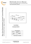
1
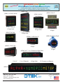
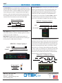
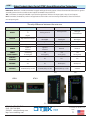
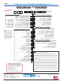
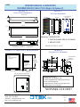
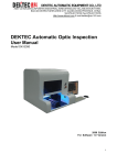
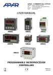
Z NEW INARY PRELIM UNIVERSAL PANEL METER (UPM) One Instrument for All Your Needs Field Configurable November 2, 2015 What is it? A DPM for >30 input Signals A Process PID Controller Scientific Controller-Display ( > 10 Math. Functions) A Universal Up/Down Timer, Counter and RTC An X-Y-Z Positioner/Controller A Data Logger (32GB) A Process Automation Controller with Relays and Analog Output An HMI Terminal with Full Alpha-Numeric Tri-Color LED Display A DCS/SCADA/PLC Terminal/Controller A Remote Display A Scrolling Message Display An Automatic Tri-Color Go-NoGo Indicator INDEX: D.P.Ms: Counters: Remote Displays: Order Information: Page 7 Page 10 Page 18 Page 20-21 PHONE: 520-748-7900 FAX: 520-790-2808 E-MAIL: [email protected] http://www.otekcorp.com A Forecasting Center ( Time/ Events to Go) A Complete Power/Quality/Generation/ Consumption Center and Controller 4016 E. TENNESSEE ST. TUCSON, AZ. 85714 U.S.A. SINCE 1974 MADE IN USA Z NEW UNIVERSAL PANEL METER NARY With Automatic Tricolor Alphanumeric Display I PRELIM UPM SERIES Analog Input: D.P.M. Digital In: U/D Counter-Timer-Clock Data Logger Serial Input: Display Relays & DAC Out: Controller (UPM-5) 3x6” (UPM-L) 2.9x1.5” (UPM-A) 1/4 DIN: 3.8x3.8” (UPM-3) ANSI 4” Switchboard 1, 2 or 3 Channels 6 Digits Each (UPM-F) Flat Pack 1, 2 or 3 Channels 6 Digits Each 1 Channel 6 Digits 1, 2, 3 or 4 Channels 6 Digits Each (UPM-X) Explosion Proof (UPM-0) 1/8 DIN 3.8x1.9” 2x3x.5; 1 Channel, 6 Digits 1 Channel 6 Digits (UPM-R), 1.5x5” Case 1 Channel 4 Digits (UPM-S) 6x1”, 1 or 2 Channels, 6 Digits Each BATCH TOTAL 1 Channel, 8 Digits 11.3x1.4” 1, 2 or 3 Channels 6 Digits Each 22 Characters on Request (UPM-4) -2PHONE: 520-748-7900 FAX: 520-790-2808 E-MAIL: [email protected] www.otekcorp.com 4016 E. TENNESSEE ST. TUCSON, AZ. 85714 U.S.A. SINCE 1974 MADE IN USA UPM™ WHAT CAN YOU DO WITH OTEK’S NEW UPM/DPM FUNCTION? All models share the same award winning software and hardware (patent pending). This allows you to implement the following applications, restricted only by the hardware limitation of each model and your imagination. Note: contact us about Otek’s Powerless™ Technology: If your signal cannot supply ≥10mW (~ 3V/3mA), use an external power model. See Page 10 for UPM-Counter functions and Page 18 for remote display. 1. One Channel Models: -0, -F, -L, -R & -X: Implement any math function, X-Y table (25 point), polynomials (9th order), offset, zero, scale, tare, log & anti-logarithmic to affect the unit’s display at will. Some examples are: change the display & data using any combination as commanded by your algorithm, such as +/-/X/÷/√ or set a variable or linearize the display using X-Y tables or polynomials. This works well for odd shape containers. You can also change the reading from F to C or K or compress/expand the display (and data out) using the log and antilog functions. In addition, you can change the factory default alarm set points and colors or delete them. Zero & Span potentiometers are included for manual adjustment. Note: Model UPM-F only offers internally accessible USB serial I/O for configuration and mathematical functions. Use digit 14 option 9 and specify your custom calibration. IF YOU DON'T SEE IT ASK FOR IT! 2. Two Channel Model: -S: Note: Also available in models with 3 or 4 channels. Features include all those of the single channel models, each channel μC is 100% isolated from each other. In addition, you can add, subtract, multiply, divide, find the square root between channels. You can also use one channel to monitor/control the input signal and the second channel to indicate deviation, differential such as PID, alarm override or one channel setpoint can be used to control another channel function. One channel may also function as a backup if the other channel becomes disabled or use them as volume & flow (√) monitors/controllers. The New Technology two channel model is also perfect as a REM/RAD indicator/controller (also see our RPM series with log-antilog functions for radiation monitoring). Contact OTEK for algorithms and formulas or any idea you wish to share with our audiences via our Youtube or Facebook page posts. 3. Three Channel Models: -3, -4 and -A: Note: Also available on 4 channel model (-5). Otek’s New Technology three channel models perform all the functions outlined in #1 and #2. Further, one channel can indicate the input variable and the other two channels can be setpoint indicators/ controllers (Hi, Hi-Hi, Low and Low-Low limits), or subject the input/output to any mathematical function or algorithm such as PID or display the input vs. output and derivative, or switch scales when the input reaches a limit/band such as for flow-volume-pressure or temperature. Monitor Volts, Amps and Watts AC or DC or any of 3 variables, including Hertz, lead/lag, power factor, peak/valley or cost by adding a KW cost multiplier. The TPM series brings Process Automation Control (PAC) within your reach and affordability. These models are compatible with any DCS/SCADA system using their USB/RS485/ Ethernet I/O options and allow for ease of interface with wireless systems. Millions of possible combinations in seconds! How? Use our award winning part number configurator for NTM & UPM: 1. Compare models 2. Build a specific part number 3. Get instant pricing 4. Build a customized user’s manual 4. Four Channel Model: -5: The four channel model offers all of the functions outlined in #1, #2 and #3. However, with the additional channel available, the UPMs rival flatscreens with superior HMI/MMI functionality and ease of viewing/ analysis of any combination of 4 variables. For example, Volts/Amps/Watts/Hertz or temperature/pressure/pH/ humidity. The four channel model can also be used to monitor/control the product of the other 3 variables, making it ideal for the petrochemical industry. The UPM offers Data Logging. Some models offer optional μSD memory to record 24/7 anything available via the serial I/O. Maximum capacity is 32 GB! NEED REDUNDANT CONTROL? Since all channels are 100% isolated from each other and the CPU can communicate with any and all MCPUs, you can use the multi-channel UPM for redundancy control. Also see our dedicated TRC (Triple Redundant Controller) that has all you need for the utmost in safety control. Build Your Own Part Number or Receive a Quote at: http://www.otekcorp.com/ configurator/nts/ -3PHONE: 520-748-7900 FAX: 520-790-2808 E-MAIL: [email protected] http://www.otekcorp.com 4016 E. TENNESSEE ST. TUCSON, AZ. 85714 U.S.A. SINCE 1974 MADE IN USA UPM SERIES OVERVIEW UPM™ All models have a lifetime warranty. The UPM, like our NTM series and the other New Technology products use multivendor sources, ultra-efficient LEDs and nanotechnology ASIC, eliminating obsolescence. THE DISPLAY: A) THE UPM-DPM: Alphanumeric Auto-Tricolor (R/Y/G) Display: The UPM has fifteen (15) segments. You can time share the display for intelligent messages to your operator when an alarm is enabled or via the serial port. You can also program the UPM to alternate between data and messages, such as: 2500 0F High Alarm; -1.050 INPT FAIL. The entire display is available for any alphanumeric character (in any one color) or you can scroll it as a continuous message (see remote display section C and page 10 for ASCII to 15 segment chart). D. P. M. (Pages 8-9): 1. It can function as a Digital Panel Meter (D.P.M.): It measures and displays data from over 30 analog input signals (see the ordering information on pages 20-21) just like a DPM. The Powerless™ input signals include A. C. and current loop and it uses the patent pending Powerless™ new technology of our NTM Series bar-digital meters/controllers. It features input signal failure detect/alarm and isolated serial I/O, all powered by the signal it measures, just like an analog panel meter (APM). Powered models can have relays/O.C.T. & analog outputs to control your process, as well as ethernet & SD for data logging. DIAGRAM PENDING ABOUT POWERLESS™ TECHNOLOGY (Digits 8 & 9, Options 00-14 only and Digit 10, Option 0): Over 40 years ago we developed this technology, and we continue to improve upon it every year! Powerless™ means the units DO NOT require any power other than what the signal can produce (just like analog meters), which is typically 10-80mW per channel. Obviously these options (00-14) can NOT drive relays or analog outputs, but they can drive the isolated O.C.T. (Open Collector Transistors), but you have to provide the Vcc! Isolated serial USB I/O is standard since it is powered by the USB host. The Powerless™ feature is only available for 4-20mA, VAC, AAC, WAC and Hertz input signals. Isolated RS485 requires 5VDC<3mA. The Input Fail detections and text is controlled by a factory set limit, but can be changed in the field or disabled (~ -0.1% of zero setting.) B) THE UPM-COUNTER: Counter-Timer-Clock (Pages 11-19): 1. All 32 functions are included and selectable via serial commands. 2. Input levels (TLL/CMOS/open collector/dry contact/high voltage) are per option number selected (see ordering information on pages 20-21). 3. Multichannel models allow you to perform all math functions between them and/or between their data stream and your serial input data. Single channel models also accept math functions or commands via the serial port. Examples: CHA + CHB/CHC – CHD; CHA – CHB + CHC +/-; OFCO/GACO or polynomial or √ or compare to your own X-Y table. Since we use floating point math, the possibilities are limited by your needs. -4PHONE: 520-748-7900 FAX: 520-790-2808 E-MAIL: [email protected] www.otekcorp.com 4016 E. TENNESSEE ST. TUCSON, AZ. 85714 U.S.A. SINCE 1974 MADE IN USA UPM™ Description & Notes (All Models) DIGIT 5, SERIAL I/O & MEMORY: Settings: 8N1N, 1200-19,200 Baud, ASCII. Digit 5, Serial I/O: Option 0, USB: Complies 100% with V2.0 and if digit 10, option 1 is selected (USB powered) then digit 5 must be option 0. Note: On model UPM-F, USB is only for factory configuration and not available for communications (unless customized). Note on USB Connectors: All models with Digit 5, Option 0 have a standard type “B” on the back. M & E grades might require “filter” connectors on back and must be specified. Use Digit 5, Option 9 and contact OTEK. Digit 5, Option 1, RS485: Complies with industry standard and will require 5VDC@<3mA and a terminating <1K Ohm resistor at first and last unit in the BUS. Not available on model UPM-F. Digit 5, Option 2 Ethernet: Complies with 1- Base-T/100BaseTX RJ45 up to 19,200 Baud. Maximum power consumption is <300mA@5V (1.5W). Only available in selected models. Connector: RJ45 on back. Digit 5, Options 3 & 4: μSD Flash Memory: μSD flash memory with up to 32 gigabytes capacity. You can store selected data at-will (i.e. when limits trip) via serial command and download or remove it as required. Connector: Same as options 0 or 1. DIGIT 6, GRADE: Industrial Grade (Options 0 or I) is per these published specifications. Option 0 is 94VO plastic, option “I” is aluminum nickel plated to Mil-Specs. Typical Mil-Specs: 461, 462, 169, 901, 801, RTCA-160, I EEE344, etc. Grades M (Mil-Spec) and E (EPRI) are per agreed specifications. Options M & E typically include EMI/RFI shield all around and filtered connectors to meet EPRI-TR-102323-R3/RTCA 160F (requiring ~2” deeper case). OTEK will build to certain nuclear or MIL-Standards but testing and confirmation of compliance (if required) will need to be done by third party and at customer’s expense. Case Finish: Plastic: ABS 94VO, black. Metal: Anodized black aluminum. M & E grades: Nickel plated aluminum, color per custom specs. UPM-X: Certified for Class I, Div. 1, Groups B-G; EX & IECex: IM2, Exd1. DIGIT 7, (# CHANNELS): See images, Table A and “Ordering Information” for # of channels available, their location and exclusive conditions. Case 0: 1 Channel/6 Characters Case 3: Up to 3 Channels/6 Characters Each Case 4: Up to 3 Channels/6 Characters Each Case 5: Up to 4 Channels/6 Characters Each Case S: Up to 2 Channels/6 Characters Case A: Up to 3 Channels/6 Characters Cases 0, F, L & X: One Channel/4-6 Characters Each Case R: 1 Channel Unicolor (red), 8 Characters Digit 5, Option 5: IRDA: Note: Only available for housing style “X” (explosion proof ). IRDA meets industry standards for infrared data reception. You can access all commands/functions without opening -X in hazardous areas. See our model IR/USB that plugs into your USB port (also see IR/232 for RS232 to IRDA). Connector: Internal μUSB. Digit 5, Option 6: TTY (20mA Current Loop): Specifically designed to interface with GA’s RM 2000 radiation transmitters. Contact OTEK for your customized TTY requirements. Only for model UPM-R. 3. Security: Password protected access to the UPM’s HW and software cyber security: contact OTEK for “CS Switch” Front Panel Controls: None for added security and safety. Note: Due to size restrictions, the UPM-R does not offer relays, O.C.T. or analog out (Digits 11 & 12 only offer option “0” ( or “None”). MULTIPLE CHANNELS (-3, -4, -5, -A & -S): All channels have the same color by default (green: >20%<80% of F.S.; red: <10>90% of F.S.; yellow: <20>80% of F.S.). You can change the color or disable the limit color or change or enable a text message in any of the three colors on limit tripping. This will help avoid operator misreadings. -5PHONE: 520-748-7900 FAX: 520-790-2808 E-MAIL: [email protected] http://www.otekcorp.com 4016 E. TENNESSEE ST. TUCSON, AZ. 85714 U.S.A. SINCE 1974 MADE IN USA UPM™ Description & Notes (All Models) {Continued} DIGITS 8 & 9 (INPUT SIGNAL): DIGIT 11 (CONTROL OUTPUTS) & DISPLAY COLORS: SECTION A Digit 11, Control Outputs: Options 1, 3, 5 or 7: Open Collector Transistors (O.C.T.): They are NOT isolated from each other See Input Signal Conditioners section (Page 7 & 8) for descrip(common emitter) but are isolated between channels and can tion and specifications. sink a maximum of 30 mA and sustain a maximum of 30VCE . When you order relays (Digit 11, options 2, 4, 6 or 8) we use the Digit 10 (Power Input): O.C.T. to drive the relays on “powered” models. 5VDC is available to drive your loads. Max total current: 50mA. O.C.T. are Digit 10, Option 0, Powerless, No Power Required: The Input ideal to drive S.S.R. for high speed switching. Power required: Fail detect/Alarm (patented) flashes the display “INPT FAIL” (INPT None. Note: Not available on UPM-F or UPM-R. FAIL) and transmits this serial message for ~20 seconds, after which it will cease. This feature is available in all models and its trip point can also be programmed by the user. If NOT desired, use option 9 on Digit 10 and specify (see below). Signal Fail Requirement: Unit must be “On” for at least 1 minute at >50% of full scale for it to operate. You can change the message via commands. Digit 11, Options 2, 4, 6 or 8: Relays: are S.P.S.T. (1C) and can switch maximum resistive loads of 1 Amp @ 120 VAC or 30 VDC. They include 300V varistors at their contacts. Power required: 250mW@5VDC/relay. AUTOMATIC DISPLAY COLORS: Limits/Colors Factory Default (% of Full Scale): Also see digit 14. Digit 10, Option 1, USB Powered: Back up Power for signal powered models: Some applications might require “keep alive” power in case the input signal fails in Powerless™ models (signal/loop powered). If you select option 1 on Digit 10 and have a USB connection, the UPM will transmit the distress message “INPT FAIL” until the signal is restored or the USB is disconnected. The VBus drives a DC-DC converter to preserve the isolation from signals and the USB. ~20mA is required from the USB. Low-Low Limit (<10%): Red Display, OCT1/K1 & OCT2/K2 “ON” Low Limit (<20%): Yellow Display, OCT2/K2 “ON” High Limit (>80%): Yellow Display OCT3 & K3 “ON” If you don’t use USB and need “keep alive” power, select options 2-4 or 9 on digit 10. The UPM “keep alive” power requirement is Hi-Hi Limit (>90%): Red Display, OCT4/K4 & OCT3/K3 “ON” <3mA@5VDC. Safe Area (>20<80%): Green will follow signal input and if outside the limits, it will change its color to the limit’s color (yelDigit 10, Option 2, Isolated 5VDC: 5VDC is also used to drive low or red). the relays (<100mA total) and/or the DAC via internal isolated 5-30VDC-DC (<200mA). If you order relays and analog out, you will need ~300mA/channel. This option is also isolated from the For other configurations , use option 9 on Digit 14 (field configurable). Max power consumption per relay: 50mA@5VDC input signal. (0.25W). See Digit 14. Digit 10, Option 3, Isolated 7-32VDC: Same as option 2 but with wide input range of 7-32VDC. Efficiency: >80%. External Control: You can control the O.C.T./Relays via the serial port with simple commands. They don’t have to be assigned to the display colors/set points, but are by default. Notes: 1. Digit 11 is governed by Digit 7 (# of Channels) & Digit 4 (Housing). Digit 10, Option 4, Isolated 90-265VAC: This option accepts 50-60Hz. For 100-300VDC or 400 Hz, use Digit 10, option 9 and specify. Efficiency: >80%. Conditions: If Digit 4 = F (flat pack) then Digit 10 must be Options 0, 2, 3 or 9 (custom). If Digit 10 = 1 (USB Power) then Digit 5 (Serial) must be Option 0. -6PHONE: 520-748-7900 FAX: 520-790-2808 E-MAIL: [email protected] www.otekcorp.com 4016 E. TENNESSEE ST. TUCSON, AZ. 85714 U.S.A. SINCE 1974 MADE IN USA UPM™ Description & Notes (All Models) {Continued} DIGIT 14 (RANGE/CALIBRATION): DIGIT 11 (CONTROL OUTPUTS) & DISPLAY COLORS: {Continued} Fail Safe: O.C.T. and relays are normally “Off ” by factory default. For “Fail Safe” mode, you can program them in the field or use option 9 (Custom) on Digit 11 when ordering and specify “Relays (or O.C.T.) normally on.” Option 0= Factory Default = 0-Full Scale=0.0-100.0 digits. Colors: <10>90%: Red; <20>80%: Yellow; >20<80%: Green. For custom colors, use Option 9 (custom) and contact Otek. Also see Control Outputs (Digit 11). You can program it for other FAIL,, LLAL, LALM,, HHAL DIGIT 12 (ANALOG /POWER OUTPUT): Digit 12, Analog Output, Options 1, 3, 5 or 7: This isolated output is factory set to follow the input (0-F.S. in=4-20 out) but can also be set for other outputs or it can be serially controlled by simple commands via the serial port. For other outputs, use option 9 and specify, including reverse scale (0-FS=20-4), bipolar and PID. Power consumption: 200mA@5VDC (1W)/channel. Note: Not available on the UPM-F or UPM-R. Analog Output External Control (Use Option 9 and specify): A) 0-100mVDC in=4-20mA out; B) 0-10K Ohm in=4-20mA out; C) Use options 58, 68, 78 or 88 and control it via serial port exclusively (no input signal). Digit 12, 30 VDC Out, Options 2, 4, 6 or 8: Use this option to power your 4-20mA transmitter or other transducer. Maximum current is 25mADC. Its isolated and is the same power source we use for options 1, 3, 5 and 7. Power consumption: 200mA@5VDC (1W)/channel. Notes: 1. Digits 11 & 12 are governed by digits 4 (Housing) & 7 (# of Channels). Reason: Digit 11 & 12 cannot have more outputs than input channels (but it can have none), which is governed by Digit 4 (Housings). DIGIT 13 (SCALE PLATE): Digit 13, Scale Plate: Option 0 is a standard scale plate that reads 0.0-100.0% or nothing depending on the model number. Use option 9 for custom printing and contact Otek. NPUT HALM ,. values, none or via the serial port. Default messages: and OTHER IMPORTANT DATA: Math Functions: +, -, x, ÷, √, Polynomials to 9th order, 25 Point X-Y table, zero, offset, span and tare. You can add, subtract, multiply, divide (etc.) one channel to/from another channel and display the result in the other channel (i.e. V (Ch.1) xA(Ch.2)=W(Ch.3). We do it for Watts on options 12, 13, 14, 7075 and 80-83. PID: Programmable (best with 2 or more channel models) automatic or manual with external 10K Ohm potentiometer (option 56). See models -X, TNT & NTT for dedicated 4-20mA transmitters (same technology). NEED A FLAT SCREEN? Why pay their price? Why send operators to school? Why buy an extra display? Why rewire you panel? Why waste your time and money? OTEK’s UPM series has it all! Intelligent display (HMI), smart communications (USB, RS485, Ethernet), 32 MB memory (μSD), mathematical functions (+, -, x, ÷, √, Log, AntiLog), look-up tables (X-Y), polynomials (9th), 4 relays or O. C. T. , analog output, etc, all verified by an independent SV&V qualifier. The series is also designed to meet specific shock, vibration, EMI/RIF, RH and temperature specifications. If our UPM is good enough for the nuclear, military and aerospace industries, aren’t they good enough for you? ABOUT OUR INPUT FAIL DETECTION Only available on Powerless™ models (8th & 9th digits, options 00-14). While in normal operation, we store excess energy and use it to power the UPM if and when the signal fails (post mortem). -7PHONE: 520-748-7900 FAX: 520-790-2808 E-MAIL: [email protected] http://www.otekcorp.com 4016 E. TENNESSEE ST. TUCSON, AZ. 85714 U.S.A. SINCE 1974 MADE IN USA Industrial Grade Common Electrical Specifications UPM™ (See Page 10 for Counters and Page18 for Remote Display/Controller) SECTION A: DPM The Powerful Powerless™ Yes! You can have the NTM powered by the input signal and have controlling outputs such as relays, O.C.T. & analog output! Input & Display: See Below For Input Signals: Note: OTEK reserves the right to change specifications without prior notice to improve the performance of its products. * A/D: Accuracy, Linearity & Resolution: +/- 0.05% of F.S. 12 Bits, Conversion Rate: 40/sec, Averaging: 0-255, zero, span, offset, tare and math functions. * Digits: Four Full Active Digits (9.9.9.9 & -1.9.9.9); 0.6” High, Alphanumeric Auto-Tricolor (R/Y/G), 15 segments * Typical Power Consumption of Display: [email protected](>[email protected]); loop/signal power version best at > 8mA. * Temperature Coefficient: +/-50PPM/°C * Operating Temperature: -10 to +60; Storage: -20 to +70°C * CCMR: >90dB@50-60Hz * Isolation: >500VDC to any other I/O & P.S. * Humidity: 5-95% RH non-condensing * Front Panel: NEMA 3. NEMA 4X on request. * Failed Signal Detect: ~ 20 seconds after > 1 minute @50% of F.S. Only on loop & signal powered models. Note 1: See page 22 for environmental specs vs. housing. How it works: Your input signal (Digit 8 & 9, options 00-14 only) powers the display, CPU, serial I/O and isolators. Your external power source powers the outputs. Benefit: You have two independent and isolated sources (fail safe). Requirement: Your signal must produce >10mW (current loop, VDC, VAC or AAC) and sustain <4V burden. If not, use external power (options 20-85 on Digits 8 & 9). AC Signal Power & Outputs? Yes, you can have both input options 01-14 (digits 8 & 9) and relays (2 maximum)without external power! Requirements: VAC input must be >90<140VAC, and AAC input must be >3<6 AAC via C.T. Ideal to monitor and control 120VAC mains! Contact OTEK for details. SECTION A: DPM INPUT SIGNAL SPECIFICATIONS (Digits 8 & 9)- See Pages 20 & 21 Note: All ±1 LSD and % full scale range unless noted. INPUT SIGNALS (Digits 8 & 9): {Continued} Option 00 For Loop Power Only: Option 00, Loop Powered: Burden: < 4V; Range: 3-26mA; Accuracy & Linearity: ±0.05% of F.S. Option 02, 5 AMP A.C. (C.T.): Burden: <100mW; Range: .3-5A; Accuracy & Linearity: ±0.2% of F.S. Best operating range to specification: 1-5 Amps. INPUT SIGNALS (Digits 8 & 9): Option 03, Watts A.C. (C.T. & P.T.): Burden: <100mW, Range: >30<750W/50-60Hz; Accuracy & Linearity: ±0.2% of F.S. Best operating range to specification: 100-500 Watts at 90-140VAC & 1-5 AAC. Worse case: ±3% outside this range. Note: Otek’s exclusive Input Fail detect (open or short) is standard on all inputs. Use option 29 and specify if you want it disabled (also field configurable). Important Note: Actual connection will vary. See the User’s Manual or the NT Catalog for specific connection information. Option 04, Hertz VAC: Burden: <100mW, Range: >30V<150V & >30<500Hz; Accuracy & Linearity: ±0.2% of F.S. Option 00 For Loop Power Only: Option 00, Loop Powered: Burden: < 4V; Range: 3-26mA; Accuracy & Linearity: ±0.05% of F.S. Option 05-14: Same as options 01 through 04 above. Options 20 through 58: For Externally Powered Only: Options 01 through 14 for A. C. Signal Powered Only Important Note: C.T. are sensitive and limited to the secondary (output) impedance. OTEK A.C. signal powered products present and input impedance of ~0.2 Ohms (~1v@5A). Make sure your C.T. can drive a >0.3 Ohm load without saturating or losing linearity. Contact Otek for assistance. Best C.T. to use: >100:5. All input channels have the same specifications unless noted. See options 60-89 for mixed signals. Option 01, VAC (P.T.): Burden: <100mW; Range: 30-150V/40100Hz; Accuracy & Linearity: ±0.2% of F.S. Best operating range to specification: 90-150VAC. Options 21 through 24, VDC: Input impedance 1M Ω; Range: Per Option; Accuracy & Linearity: ±0.05% of F.S.. Option 20, 4-20mA: Burden: <25 Ohm (0.5V); Range: 3-26mA; Accuracy & Linearity: ±0.05% of F.S. -8PHONE: 520-748-7900 FAX: 520-790-2808 E-MAIL: [email protected] www.otekcorp.com 4016 E. TENNESSEE ST. TUCSON, AZ. 85714 U.S.A. SINCE 1974 MADE IN USA UPM™ SECTION A: UPM-DPM INPUT SIGNAL SPECIFICATIONS (Digits 8 & 9) Options 25 & 26, mADC: Input impedance Option 25: 50Ω; Option 26: 5Ω; Accuracy & Linearity: ±0.05% of F.S. Option 27, Watts DC (1Vx1A DC): VZin: 1M Ω/AZin: 1.0Ω, 5W; Range: 1W; Accuracy & Linearity: ±0.1% of F.S. Option 47 & 48, RTD: 47: 100 Ω (PT100); 48: 1K Ω (PT1000); Range: same as RTD; Excitation: 0.5mA; Accuracy & Linearity: ±0.5% of F.S. 2, 3 or 4 wire RTD. For 3 wire, connect -E to -S. For 2 wire, also connect +E to +S. Warning: Max distance to sensor: ~ 300 Feet (100 M) or use our -X, TNT or NTT transmitters. Option 28, Watts DC (1Vx1V): VZin: 1M for both inputs; Range: 0-1V; Accuracy & Linearity: ±0.1% of F.S. NOTE: Always use P.T. or C.T. with H.V. Lines (Options 30-34). Note for Options 47-52: You can switch from F to C via serial port or use option 29 and specify. Default: F (uses internal linearized table). Options 30 through 34: VRMS: Zin: 1MΩ; Range; per options; Accuracy & Linearity: ±0.1% of F.S. Option 50, Type “J” TC: Range: -210 to 760C; Colors: red and white; CJC: Included; Accuracy & Linearity: ±2C of F.S. Options 35-37, Amps RMS: Zin: Option 35: 2Ω; Option 36: 0.2Ω; Option 37: 0.04Ω; Range: Per option; Accuracy & Linearity: ±0.1% of F. S. Option 51, Type “K” TC: Range: - 270 to 1370C; Colors: Yellow and red; CJC: Included; Accuracy & Linearity: ±2C of F.S. Option 38: Watts RMS (1Vx1V AC/DC): Zin: 1MΩ for both inputs; Range: 1V RMS; Accuracy & Linearity: ±0.2% of F.S. Option 52, Type “T” TC: Range: -270 to 400C; Colors: blue and red; CJC: Included; Accuracy & Linearity: ±2C of F.S. Option 40, Watts RMS (120VAC P.T. x5AAC C.T.): Zin: 1M for V & 0.04Ω for A; Range: 0-750W; Accuracy & Linearity: ±0.2% of F.S. Note: Shunt resistor (0.04Ω) supplied. Note for Thermocouples (TC): Shorting out the +/-TC terminals will display the ambient temperature of the C.J.C. at the terminals. Option 41, Frequency (10KHz/5V Logic): Zin: 1M; Range: 30- Option 53, pH: Range: 0-14.00; Zin: >1015Ω; Temperature compensation: None; Accuracy & Linearity: ±0.05% of F.S. 10KHz; Accuracy & Linearity: ±0.1% of F.S. Option 42, Hertz (120V, 40-100Hz): Zin: 1M; Range: 50-150VC/40-100Hz; Accuracy & Linearity: ±0.1% of F.S. Option 54, ORP: Range: 0-2000mV; Zin:>109 Ω; Accuracy & Linearity: ±0.05% of F.S. Option 43, Hertz (240V, 30-100Hz): Zin 1 M; Range: 100-260V/30-100Hz; Accuracy & Linearity: ±0.1% of F.S. Option 55, % RH: Range: Per sensor; Input Type: 2-3 pF Capacitance; Accuracy & Linearity: ±0.05% of F.S. State sensor’s specifications. Option 44, Hertz (120V, 500 Hz): Zin: 1 M; Range: 50-150V/300-500Hz; Accuracy & Linearity: ±0.2% of F.S. Option 56, Resistance Range: 0-10K Ω=0-100%=0-100.0; Accuracy & Linearity: ±0.1% of F.S. For 240 VAC/400 Hz, use option 29 & specify. Option 58, None: Serial input only as per Digit 5 for remote/ display controller. Note on Strain Gages: Specify impedance, sensitivity, range and calibration. Example: 350 Ohms, 2mV/V, 10mV=0-100%. Options 60-89: Option 45, Strain Gage (<1KΩ): Excitation: 4V; Range: 300-1K Ω; Accuracy & Linearity: ±0.1% of F.S. For multichannel mixed signals. Same specifications as per options 20 through 56. Option 46, Strain Gage (>1KΩ): Excitation: 4V; Range: 1K-5K Ω; Accuracy & Linearity: ±0.1% of F.S. -9PHONE: 520-748-7900 FAX: 520-790-2808 E-MAIL: [email protected] http://www.otekcorp.com 4016 E. TENNESSEE ST. TUCSON, AZ. 85714 U.S.A. SINCE 1974 MADE IN USA 14 SEGMENT ALPHANUMERIC CHART (ASCII) UPM™ Notes: 1. You can “tag” any message (or none) when the set points are enabled or at-will via the serial port. 2. You can change the color when the set points are enabled (see Page 7, Digit 14) or at-will via simple commands 3. If you want customized messages, use option 9 on Digit 14 and OTEK will program it for you! Decimal Hexa-Decimal ASCII 5 97 41 61 A A 66 98 42 62 B B 67 99 43 63 C C 68M 100 44 64 D D 69 101 45 65 E E 70 102 46 66 F F 71 103 47 67 G G 72 104 48 68 H H 73 105 49 69 I I 74 106 4A 6A J J 75 107 4B 6B K K 76 108 4C 6C L L 109 4D 6D M M Decimal Hexa-decimal ASCII 48 30 0 49 31 1 50 32 2 51 33 3 42 34 4 53 35 5 54 36 6 55 37 7 56 38 8 57 39 9 Decimal 110 111 112 113 114 115 116 117 118 119 120 121 122 78 79 80 81 82 83 84 85 86 87 88 89 90 Hexa-Decimal 4E 6E 4F 6F 50 70 51 71 52 72 53 73 54 74 55 75 56 76 57 77 58 78 59 79 60 70 ASCII N O P Q R S T U V W X Y Z N O P Q R S T U V W X Y Z 0 1 2 3 4 5 6 7 8 9 Simple Serial Commands (See Command Set and Ordering Information) •Batch •Integration (Totalizer) •Phase Angle •Rate •Stop Watch •Zero Datum •OFFCO, GACO, TARE •Custom: Contact OTEK if not listed here •Draw •Julian Clock (RTC) •Logarithmic (Anti-Log) •Quadrature •Rads •Ratio •REMs •Time Interval •Up/Down Counter •Math Functions •User’s X-Y Tables •ZERO, and SPAN: Only for analog input signals •Frequency •Period •Range •Square Root •Voltage to Frequency •User’s Polynomials -10PHONE: 520-748-7900 FAX: 520-790-2808 E-MAIL: [email protected] www.otekcorp.com 4016 E. TENNESSEE ST. TUCSON, AZ. 85714 U.S.A. SINCE 1974 MADE IN USA UPM™ WHAT YOU CAN DO WITH THE UPM-COUNTER: First of all, you can enable any listed functions (1-9 and A-L) on Digit 15, but you must select the input level by selecting options 1A-4A or 1B-4B or 1C-4C on Digits 8 & 9 when ordering. Since the UPM-Counter is field programmable for any listed function, you have a truly universal counter at your warehouse! No need to order a timer only, or any other needed functions and hold your production until arrival. Assume you have a 3 channel UPM-Counter assigned for Ch. A: Frequency; Ch. B: Batch; and Ch. C: Rate, and you need to display/control the total. all you need to do is connect your laptop’s USB to the UPM-Counter and change the least needed function to totalizer, set your limits and colors and continue your process. HOW DO WE DO IT? 1. Each channel has its own isolated ASIC, signal conditioner DAC, relays/SSR and power supply. 2. The isolated CPU communicates and can control each and all P (common serial port). 3. All available functions, including match functions, algorithms can be implemented on any and all channels via simple serial command. This includes continuous data streams that can be compared with each other. This is ideal for redundant control! What’s Redundant Control? Suppose your nuclear vessel temperature is being monitored by a 3 channel UPM-DPM (or UPM-Counter for RAD counting) and channel A trips its high limit, but channels B and C do not. After comparing the data from all 3 channels, the UPM-DPM applies the democratic majority rule, disables channel A, sends a report via the serial port, enables warning visual messages/color and/or relays and/or analog outputs. The rest is up to you. UPM BLOCK DIAGRAM μ SD 32GB DAC A ISOL. UART A μP A USB UART B μP B RS485 UART C μP C ETHERNET C D μP D CPU/RTCC RELAYS A A/D A SIGNAL A AC/DC POWER SUPPLY DAC B A/D B SIGNAL B RELAYS C ISOL. POWER RELAYS B DC-DC A CHN A DAC C DC-DC B CHN B A/D C DC-DC C CHN C DC-DC D CHN D SIGNAL C OTEKCORP.COM -11PHONE: 520-748-7900 FAX: 520-790-2808 E-MAIL: [email protected] http://www.otekcorp.com 4016 E. TENNESSEE ST. TUCSON, AZ. 85714 U.S.A. SINCE 1974 MADE IN USA UPM™ SECTION B: COUNTERS B) THE UNIVERSAL COUNTER/TIMER CLOCK (Digit 15, Options 1-9 and A-L): Input and Output Terminals and How To Use Them: Note: Not to be confused with input signals for measurement. The UPM can function as a universal counter: It accepts digital inputs to perform over 20 functions, all of which can be selected by serial input commands. Functions: Batch – Debouncer – Draw – Frequency – Integrations – Julian Clock (RTC) – Log/Anti-Log Extractor – Period – Phase Angle – Positioning – Quadrature – Range – Rate (1/F) – Ratio– Square Root – Stopwatch – Time Interval – Totalizer – Up/Down Counter –Up/Down Timed (Milliseconds to years!). Features: Fully configurable for any listed function via serial port. * Same features as DPM section except it is only offered in external power (Digit 10, options 1-4). * Same features as NTM series except it has an Alpha-Numeric Tricolor Display instead of a bargraph. *Multiple isolated displays (up to four) allow for complex math functions/display/control of process variables such as Volts/ Amps/Watts/Frequency/Pressure/Flow/Volume and temperature, and PID or redundant control. * Three angle positioning (X, Y, Z). * Intelligent (HMI) moving messaging (up to 18 characters). * Automatic process control (MMI) and much more. Besides the regular input signal terminals, the UPM has other external terminals to control its functionality. These functions can be enabled via serial command or managed by the internal function selected. Refer to customized user’s manual. Terminals that are already dedicated and controlled externally have a 5K pull up to the isolated 5VDC of its channel and only accept 5V logic levels or dry contacts. Borrow (only in the first stage of a string): Connect “Borrow” pin to “Carry” pin of previous unit (or channel) to expand the number of channels. Carry (only in the last stage of a string): Connect “Carry” pin from the first unit to the “Borrow” pin of the next unit (or channel) to expand the number of characters. Count Hold (Digit 15, Options 5, K, L): “Grounding” this pin (5K pull up) forces the counter to stop counting. Display Hold (Digit 15-, Options F, K): “Grounding” this pin (5K pull up) holds the display, but allows the counter to continue counting. Frequency out (Digit 15, Options 5, F, K): This pin is the F out of the signal conditioner after it has been converted to 5V logic levels. Minimum load=1K Ohm. Useful for F-V. Run/Stop (Digit 15, Option G): This pin is functionally the same as “Counter Hold” except has a <1S response time. Frequency Response (No De-Bouncer): Useful for DCS/ SCADA/PAC interface, <1S response time. -12PHONE: 520-748-7900 FAX: 520-790-2808 E-MAIL: [email protected] www.otekcorp.com 4016 E. TENNESSEE ST. TUCSON, AZ. 85714 U.S.A. SINCE 1974 MADE IN USA SECTION B: COUNTERS Input and Output Terminals and How To Use Them (Continued): Reset (Digit 15, Option 5): This pin is used to reset the internal accumulated count and has no De-Bouncer since its used in “Frequency” counter (up/down) modes.Response time:<1S. Multiplier: (also see “Divider”) In some applications the input data needs to be multiplied to arrive at unity count such as tanker to barrels, barrels to gallons, gallons to liter, etc. Select the appropriate multiplier of your choice with up to four decimals (xxxx.yyyy). Divider: (also see “Multiplier”): Some applications require counting in multiples of units such as dozens/bag, gallons/barrel, liters/cask, etc. Just select the divider number and count in desired unit of measurement (1/2, 1/56, 1/500, etc.). Up/Down (Digit 15, Option 3): Leave this pin open for “UP” count or “ground” it for “DOWN” count. If connected to an encoder, connect “UP” into “A” and “DOWN” into “B” and “RESET” to “Z” for rotary zero detect encoders. Inputs/Functions (Digits 8 & 9 and 15): Conditions: If digits 8 & 9 have options 00 through 58, 60-68, 70-78 or 80-88, then digit 15 must be option “0 (None).” Up/Down Counter (Option 1): (also see “Quadrature” counter) A counter is a totalizer that can be enabled/disabled by several means such as an input (gate), a command (serial), or a result of another action produced by your algorithm, such as CHA + CHB/CHC = 0. Therefore, start/stop counts or times on CHD, which can be useful to synchronize 3 phase power lines or radiation counters. If you use the F-V option, you can convert analog signals to digital format for higher accuracy synchronizing. Imagine the possibilities limited by your algorithm! UPM FIG 1: u/DC, Option 1 Quadrature (Option 3): (also see “Datum Zero”) This function includes inputs for Input A (count), Input B (direction), and Input Z (datum zero). When Input A rising edge ( ) leads Input B rising edge, the UPM will increment its count by one (1). When Input B leads Input A, it will decrement its count by one (1). Regardless of Logic state of Inputs A or B, when Input Z transitions from Logic 0 to 1, the UPM will reset to zero. This is important when using rotary encoders to indicate the zero degree point. Again, the resolution of the measurement is determined by the number of pulses/rotation of your encoder and the multiplier you select. But you can display/control the process in decimal or clock (360°:60M:60S) format. Linear encoder is used for length measurements/control, rotational encoders for rotational (degrees) applications. The automatic tricolor change will warn the operator of anomalies. The UPM can be forced to zero count via a serial command or an OR connection at the Z Input since it has a 10KΩ pull up to 5V (high to reset to zero, low to run). The Z (zero) pulse should be as short as possible (>1S) to avoid missing a count. ZERO UP/DOWN COUNT IN 0 1 2 3 4 5 6 5 4 3 2 1 0 -1 -2 -3 -2 -1 0 1 2 3 4 Totalizer (Counter) (Options 2 & 1A-4C): This function accumulates the number of pulses received on Input A after Input B has been taken high ( ), will sum the events for as long as Input B remains high and will decrement on the falling edge ( ) of Input B. You can switch the logic of Inputs A and B via simple commands and by using the command “TOTDN” (totalizer down) instead of “TOTUP” (totalizer up), you can enable any controlling output/message (relay, O.C.T., DAC, color change, message, etc.). UPM FIG 3: Quad A, Option 3 UP/DOWN COUNT IN 0 1 2 3 4 5 6 5 4 3 2 1 0 -1 -2 -3 -2 -1 0 1 2 3 4 SERIAL COMMAND: CTR RESET -13PHONE: 520-748-7900 FAX: 520-790-2808 E-MAIL: [email protected] http://www.otekcorp.com 4016 E. TENNESSEE ST. TUCSON, AZ. 85714 U.S.A. SINCE 1974 MADE IN USA UPM™ SECTION B: COUNTERS 3.1 Zero Datum: (also see “Quadrature” and “Up/Down” Counter) This single pulse/revolution is produced by rotary encoders to indicate 0° and it is used by the UPM to zero its display and start counting up or down in a degree fashion with degrees, minutes, second, and milliseconds of rotation determined by the resolution of your encoder. For linear measurements, use command “LIN.” For rotational, use the command “ROT.” Frequency (Option 5): Use “Frequency” to totalize the number of pulses over a fixed measure of time. Example: 60 Hz = 60 cycles or pulses/second such as a household electrical line, 94.652 MHz might be the transmitting frequency of a radio broadcaster, etc. Note: “Frequency” is normally defined as events (pulses) per second (10/s, 1k/s/MHz). “Rate” is defined as events (pulses) per minute, hour, day for slow-occurring events versus a unit of time. See Rate (1/F), such as in oil rigs. UPM FIG 3.1: Quad B, Option 3 UPM FIG 5: Frequency, Option 5 ZERO UP/DOWN INPUT COUNT IN 0 1 2 3 4 5 6 5 4 3 2 1 0 -1 -2 -3 -2 -1 0 1 2 3 4 1 HZ GATE TIME SERIAL COMMAND: CTR RESET Batch (Option 4): Use “Batch” to count or measure specific amount of product in a container. Example: gallons in a barrel, peanuts in a jar, pills in a bottle, etc. Batch Total: Use “Batch Total” to add the total number of batches of a specific product. Example: barrels in a tanker, jars in a box, boxes in a skid, skids in a truck, etc. UPM FIG 4: Batch, Option 4 A INPUT B INPUT COUNT LIMIT 5.1 De-bouncer/Filter: UPM’s Debouncer (Filter) function is useful when the input signal is from relay contacts that “bounce” or are of an AC nature. Select a “debouncer” time base that covers the worst case condition of the bouncing signal. Relays typically have a bouncing time of 5–20mS, so a time base >25mS will be safe to use. However, if the switching (on-off ) speed of the relay is <30mS, you should not use a time base greater than 25mS. The best time base would be approximately >15 and <20mS. This is also useful for AC power lines (>18mS for 60 Hz, >22mS for 50 Hz, or >3mS for 400 Hz power lines). UPM FIG 5.1: De-Bounce, Option 5 INPUT ACTUAL COUNT IF YOU DON'T SEE IT ASK FOR IT! -14PHONE: 520-748-7900 FAX: 520-790-2808 E-MAIL: [email protected] www.otekcorp.com 4016 E. TENNESSEE ST. TUCSON, AZ. 85714 U.S.A. SINCE 1974 MADE IN USA UPM SERIES (Continued) UPM™ SECTION B: COUNTERS 5.2 Burst: There are applications where it is desirable to measure the “burst” of a frequency input and ignore the base frequency. In this case, select a gate time > the minimum (maximum normal) burst frequency. Example: Normal: < 1 kHz, burst > 1.5 kHz < 20 kHz. Select a gate of 1.4 mS. The UPM will only display the burst’s frequency of approximately 3.2 kHz. Want to count the number of bursts? Enable the counter function and the UPM will display the number of bursts since last reset. RADs (Option 7): Also known as units of radiation (radiation absorption dose) or “grey” units in SI. Radiation transmitters/ sensors produce either analog output (4-20mA) or pulses. If pulses per “grey,” you can accumulate (totalize) the number of pulses over a period of time. If analog, you can integrate logarithmically the total “dose.” See integrator. UPM FIG 5.2: Burst, Option 5 <1k HZ>1.5K HZ <1KHZ >1.5K HZ DIAGRAM PENDING A INPUT ACTUAL COUNT 2174 1525 Period (Option 6): Use “Period” to measure/control the duration (width) of a signal transition from Logic 0 to Logic 1 (low -> high). Its measurement resolution is determined by the gate time selected (10 μS to 10 sec.). Again, you can use the math functions to meet your algorithm needs such as CHA + CHB, CHA – CHB, CHC x CHD, CHC/CHB/√, etc. UPM FIG 6: Period, Option 6 REMs (Option 8): A.K.A. Si (Sievert). Radiation detectors/ transmitters produce either a pulse per unit of radiation (~0.01 Sievert) or analog signal (usually mV or 4-20mA). In either case, the UPM accepts both signals and if pulsed, it totalized the number of pulses received. If analog, it uses the integration function, along with the log or anti-log (contracting or expanding) for the reading and gives you the accurate rate (dose) of accumulated radiation in an area. A INPUT TIME DISPLAY 12.613 3.093 312.924 DIAGRAM PENDING -15PHONE: 520-748-7900 FAX: 520-790-2808 E-MAIL: [email protected] http://www.otekcorp.com 4016 E. TENNESSEE ST. TUCSON, AZ. 85714 U.S.A. SINCE 1974 MADE IN USA UPM™ SECTION B: COUNTERS Custom (Option 9): Contact OTEK for your custom algorithm/ application. Time : There are three (3) times: time interval (Option B), elapsed time (Option C) and range time (Option D). Typical custom design that replaces F, F & F obsolete 20mA C.L. (teletype) input 1960’s technology with the UPM-R. Elapsed time means time that has occurred from the starting point and range time means estimated time to end of task (if all conditions remain as they are). Elapsed time requires a time base selection, a “Start” pulse and an “End” pulse, both rising edge (positive Logic). Range time requires a time base selection (mS to seconds), a reference input signal (events/time base), and a “Total” goal or destination value. Note: You can enable/disable the up/down function via serial command. Up/Down Timer (Option A): Just like the Up/Down Counter (Option H), but instead of using external pulses to count, the UPM uses its internal programmable time base to increment/ deincriment its count. Default is one (1) second, range is 1 s to 10 seconds. Example: Assume you want to know how long it will take to fill a tanker, whose capacity is 164,000 barrels, at a present rate of 3450 barrels/hr. However, if the rate varies to 2945 or 3649/hr, how long will it take in seconds, minutes, hours, or days? The UPM will automatically update its display and serial output as well as its analog output (for PID control) to inform you of the calculated end of process. All math functions are available for you to automatically select multipliers, dividers, or external variables as required. Also, you can use the V-F input option to convert analog inputs (4-20 mA, 1-5 V, etc.) to events for the range time algorithm. If you have a mileage “Range” indicator in your car, the UPM’s range function works the same. DIAGRAM PENDING -16PHONE: 520-748-7900 FAX: 520-790-2808 E-MAIL: [email protected] www.otekcorp.com 4016 E. TENNESSEE ST. TUCSON, AZ. 85714 U.S.A. SINCE 1974 MADE IN USA UPM™ SECTION B: COUNTERS Time Interval (Option B, continued): This measures the time interval between two (2) inputs A and B and starts on the rising edge ( ) of Input A and stops on the rising edge ( ) of Input B. Alternatively, you can select the falling edge ( ) or start with Input B and select your time base (μS to seconds) and any actions to occur (relay, O.C.T, display change, math functions, average, etc.). If you use a “Gate Time” function, you can display/control the average of all the pulse widths that occurred during the gating time. Range (Option D): This function is extremely useful in determining how long (range) the asset your have (fuel, beans, water, etc.,) will last you if you maintain the present usage at the present rate. It’s no different than a retiree wishing that his money will outlast him, or wondering if you have enough gas to get to the next gas station or calculating whether the rods in a reactor will last until the next “load” arrives. All you need to do is enter the value of “In Stock,” and the UPM will use prior (if programmed into the memory) information to determine the range. You can also enter the rate/unit (unit=time, events, etc.) and the UPM will calculate the range. DIAGRAM PENDING DIAGRAM PENDING Elapsed Time (Option C ): Depending on the model selected (number of characters/digits), you can display/control events in days, hours, minutes, seconds, mS, and μS (D:365, H:24, M:60, S:60, μS:000,000 for a 15 digit model(s) or 5 digits for the smallest package (-L). Use the relays, O.C.T. or analog output to control your process by setting limits/alarms (usually 00:00:00). DIAGRAM PENDING -17PHONE: 520-748-7900 FAX: 520-790-2808 E-MAIL: [email protected] http://www.otekcorp.com 4016 E. TENNESSEE ST. TUCSON, AZ. 85714 U.S.A. SINCE 1974 MADE IN USA UPM™ SECTION B: COUNTERS Rate (Option F): (also see “Frequency) Rate is used for slow occurring events such as strokes/minutes, GPM, LPM, barrels/day, etc. instead of fast occurring events which are measure in Hertz (usually seconds) such as radio frequencies or power lines. Julian Clock {RTC} (Option E): Use “Julian Clock (RTC)” to indicate time, date, and year and control any loads via the four relays or analog output (4-20 mA) of any channel. Four and five digit models alternate the display as follows: 2014 (year) **12 (mo.) **27 (date) 10:15 or 20:15 (hrs and min) 45.07 (sec and mS) or 2014 (year) *159 (day) **27 (date) 10:15 or 20:15 (hrs and min) 45.07 (sec and mS) or month, date, year, time or time, data, month, year. DIAGRAM PENDING F.1 Digital Mode Rate: Rate uses the 1/F formula to arrive at the rate per unit of time by counting the number of events that occur within the time base used. If you want to measure/control the process that produces approximately 1/second, use the 1 or 10 second time base. This will give you a reading of approximately 60 EPM (events/minute) or 3600/hr with fractions of an event (3600.3), if required. This is commonly used in oil rigs to measure the barrels/day produced without using a flow meter. Place any callout in any order and use “*” to indicate dead space. Enable/disable any on-off (Relay/O.C.T.) at any specific time/date/year or analog output to any value. Example 1: K1ON 2015**08 **15 07:15; K1OF 2015**09 **01 *9:30; Turns on Relay K1 on August 15th at 7:15 a.m.; turns Relay K1 off on September 1st at 9:30 a.m. in year 2015. Example 2: DIAGRAM PENDING 2015 (year)*AN1 *4.00 (mA) **10 (month) **19 (date) 23:59 (time) 2015 (year)*AN1 *8.50 (mA) **10 (month) **20 (date) 05:30 (time) 2015 (year) *AN112.00 (mA) **10 (month) **20 (date) 09:30 (time) 2015 (year) *AN116.00 (mA) **10 (month) **20 (date) 12:30 (time) 2015 (year)*AN1 20.00 (mA) **10 (month) **21 (date) 2400 (time) Turns analog out to 4.0 mA on October 19th of 2015 at 23:59 (11:59 p.m.), holds it at 4 mA, then switches its outputs to 8.50 mA on the 20th of October at 5:30 a.m., then to 12.00 mA on October 20th at 9:30 a.m., then to 16.00 mA on the 20th of October at 12:30 p.m., then to 20.00 mA on October 21st of 2015 at 12 midnight (2400 hours). Date/Time: You can make your own format to suit your country’s needs. Just identify the label and sequence in moving message. You can control any and all four Relays and DAC per channel at will. Default format: U.S. standard: month – date – year – hour – minute – second. Note: Models with 12+ characters (-4 and -S) are best suited for calendar-controlled functions. F.2 Analog Mode Rate: If your process produces an analog signal such as 4-20 mA, 1-5 mA, 1-5 V, 0-10V or other, you can use our option 1C, 2C, 3C or 4C (voltage to frequency) to convert/ scale the analog to digital form and follow the example noted in Digit Mode Rate C.1. Rate is used to calculate/display the frequency of slow occurring events in a short period of time (seconds) without having to wait minutes, hours, or days to find their frequencies. All you need to do is select the time base (gate) in 0.1, 1, or 10 seconds and multiplier (60 [M], 3600 [H], 86900 [D]) to determine the unit of time. DIAGRAM PENDING -18PHONE: 520-748-7900 FAX: 520-790-2808 E-MAIL: [email protected] www.otekcorp.com 4016 E. TENNESSEE ST. TUCSON, AZ. 85714 U.S.A. SINCE 1974 MADE IN USA UPM™ SECTION B: COUNTERS Ratio (Option G): Ratio is the ratio of two (2) signals (A/B) to determine their positive (greater) or negative (smaller) frequency vs. each other. Normally, it is used to synchronize their zero crossings such as in power lines (synchroscopes), other matching frequency applications (radio broadcasts), or conveyor speed synchronization. Using the UPM analog output as proportionally controlled by the output of the “Ratio” function can automatically synchronize the objects similar to PID. V-F {Voltage to Frequency Converter} (Option K) : The UPM series offers an optional high accuracy and resolution V-F (also F-V) Converter capable of converting a 0-1 V signal (or 4-20mA and others on request) to 0-100 kHz giving you a 0.00001V (10μV) resolution (+/-0.000001% of full scale). When you use this option, converting pressure to flow and/or volume using the √ function becomes a very economical and accurate alternative to old techniques. DIAGRAM PENDING DIAGRAM PENDING Phase Angle (Option H): (needs 2+ inputs) It measures the phase relationship between any two inputs and its value is displayed in degrees (0:00:00 to 360:00:00) formatted DDD:MM:SEC.000 (degrees, minutes, seconds, and milliseconds of rotation). Best with 6 digit models. DIAGRAM PENDING Integrations (Option L): Use “Integration” to integrate, accumulate or totalize events (pulses) over an open period of time (seconds, minutes, hours, days). Also see “Totalizer,” “Event Counter,” “REM Counter,” Logarithmic,” “Anti-Log,” and “Volume.” Using our V-F (voltage to frequency counter) option, you can convert analog signals to frequency, such as pressure to flow and volume using our “Square Root” extractor function. Examples: TBW DIAGRAM PENDING Draw (Option J): Use “Draw” to measure/control two variables that should maintain identical amounts, speed, velocity, etc. Draw = A/B – 1 is same as “Ratio,” but 1 unit is subtracted from it to give you a zero display (differential) when their ratio is 1:1. Example: Two conveyors should be travelling at the same speed/tension/level and the UPM will display the differential between them. L.1 Square Root: This standard feature of the UPM allows you to convert the differential pressure from a pressure transmitter to instantaneous flow, and if you enable the integrator mode, to accumulate (per unit of time) the flow into volume. DIAGRAM PENDING DIAGRAM PENDING -19PHONE: 520-748-7900 FAX: 520-790-2808 E-MAIL: [email protected] http://www.otekcorp.com 4016 E. TENNESSEE ST. TUCSON, AZ. 85714 U.S.A. SINCE 1974 MADE IN USA UPM™ SECTION C: REMOTE DISPLAYS SECTION E: OTHER USES C) REMOTE DISPLAYS (Digits 8 & 9, options 58, 68, 78 or E. OTHER USES: 88): E.1 It can function as a scientific meter: It performs math functions (+, -, x, ÷√X-Y tables, polynomials, range, log-antilog with exponential (ideal for RAD/REM a.k.a. Gy/SV). As a remote (serial input) display, the UPM has no analog or digital inputs enabled or tested, but it can have On-Off Control (Digit 11) and/or Analog Outputs (Digit 12). This will allow you to control your process with your own commands/algorithm and simultaneously display an intelligent message to the operator (HMI/MMI). Imagine the possibilities! E.2 It can function as a smart message center: We use ultraefficient 15 segment automatic tricolor (R/Y/G) LEDs for full alphanumeric display. Number of characters vary with model. Serial I/O includes isolated USB, RS485 or Ethernet. DIAGRAM PENDING SECTION D: CONTROLLERS D) CONTROLLER: It can function as a controller: It includes an isolated optional analog output (4-20mA) that is internally powered and capable of driving up to 1K Ohm loads. The SPDT relays (4/channel) are capable of driving up to one (1) Amp at 120VAC/30VDC resistive loads. 300V MOVS are included. The open collector transistors (O.C.T.) are isolated from the signal and power inputs and can drive up to 30mA@30VDC/VCE, such as S.S.R. DIAGRAM PENDING DIAGRAM PENDING CUSTOMS Class 1E (Nuclear Safety), Military (to specific MIL-Specs) and industrial grades are available. We have been supplying our armed forces, and the aerospace and nuclear industries for over 30 years. E3. It can function as a data logger (paperless recorder): Some models include an optional removable 32GB μSD memory card for data storage and it is configurable to meet your needs via simple commands. Standard factory configuration is when any limit is reached and include the units I.D. number, name, run time stamp, limit data and message. DIAGRAM PENDING E.4 ABOUT ISOLATION: All models in the OTEK New Technology series include 100% isolation (>500VDC) between ALL I/O, including serial I/O, power input, control outputs (relays and O.C.T.), analog outputs and signal (analog or digital) inputs. The UPM-F is “display only” and has no outputs. CONCLUSION: As you can see, the UPM is truly the Universal Panel Meter you have been waiting for. All the listed functions (and more) are included and found in the User’s Manual, making the UPM a versatile microcomputer with controlling capabilities superior to a PLC and inferior to it in cost and size. You can use it to perform most any task. If not, contact us to solve the problem together. Use Note: Remember the UPM’s recording capabilities with its exclusive 32 GB memory capacity. That can save you lots of headaches. -20PHONE: 520-748-7900 FAX: 520-790-2808 E-MAIL: [email protected] www.otekcorp.com 4016 E. TENNESSEE ST. TUCSON, AZ. 85714 U.S.A. SINCE 1974 MADE IN USA UPM™ Other Products that a Part of OTEK’s Award Winning New Technology: NTM Series: Barmeters: Include autotricolor bargraph and digits for analog inputs. Choose from 20 models that can be signal or externally powered and can include control outputs (4-20mA & 4 relays/channel). TNT: Transmitters (4-20mA) for DIN-Rail or panel mount applications with over 30 input signals, relays (2) and outputs. NTT: Transmitter (4-20mA) for panel mount applications and include serial or manual (potentiometer) control and include over 30 input signals. The only differences between the series are: FEATURES UPM NTM TNT NTT INPUTS Analog, Serial & Digital Analog & Serial Analog & Serial Analog & Potentiometer DISPLAY Alpha-Numeric Tricolor Tri-Color Bar-Digital Tri-Color Bar-Digital Tri-Color Bar-Digital TRICOLOR BAR None 51 Segments 51 Segment 51 Segment # OF DIGITS Up to 18 4 4 4 POWER Signal or External Signal or External External External SIGNAL CONDITIONERS >30 Analog & >20 Digital >30 Analog Only >30 Analog Only >30 Analog Only USB/485/ ETHERNET Yes Yes Yes Yes MEMORY Yes Yes On Request On Request OUTPUTS 4-20mA, Relays or SSR 4-20mA, Relays or SSR 4-20mA, Relays or SSR 4-20mA TNT UPM-L NTT NTM-L -21PHONE: 520-748-7900 FAX: 520-790-2808 E-MAIL: [email protected] http://www.otekcorp.com 4016 E. TENNESSEE ST. TUCSON, AZ. 85714 U.S.A. SINCE 1974 MADE IN USA UPM™ UPM SERIES ORDERING INFORMATION 11-2-15 Please refer to option descriptions/conditions on pages 5-20 before selecting. See ordering information notes {1-6} on page 23. **Contact Otek For *Contact OTEK at 520-748-7900 INARY PRELIM or at [email protected] for model availability. U P M - 4 5 6 - 7 8 9 *HOUSING (BEZEL DIMENSION & MATERIAL) Note: Digits/channels can be stringed for text messages. Note: Grades E, M & 9 might require an N.R.E. fee. SERIAL I/O 0.......................................................USB 1....................................................RS485 2.................................................Ethernet 3............................USB & μSD Memory 4.........................RS485 & μSD Memory 5....................................IRDA (-X Only) 6...........TTY (Remote Display, -R Only) 9.......................Custom (Contact OTEK) SCALE PLATE 0.................Standard (0-100%) 9.......Custom (Contact OTEK) 1......................................One 2......................................Two 3....................................Three 4.......................................Four 9......Custom (Contact OTEK) INPUT SIGNAL {2-6} See Page 23 and enter option number for Digits 8 & 9. Example of Good Part Number: UPM-500-480-488-00 Example of Bad Part Number: UPM-300-480-488-00* *Red Numbers are conflicting options) PHONE: 520-748-7900 FAX: 520-790-2808 E-MAIL: [email protected] www.otekcorp.com DIGIT 14 DIGIT 13 ANALOG/POWER OUTPUT 0...............................................None 1....CH. 1.................4-20mA Out (1) 2....CH. 1.......................30V Out (1) 3....CH. 1 & 2..........4-20mA Out (2) 4....CH. 1 & 2................30V Out (2) 5....CH. 1, 2 & 3......4-20mA Out (3) 6....CH. 1, 2 & 3............30V Out (3) 7....CH. 1, 2, 3 & 4..4-20mA Out (4) 8....CH. 1,2, 3 & 4.........30V Out (4) 9.................Custom (Contact OTEK) # OF CHANNELS DIGIT 8 & 9 Availability for Digit 15 options 1-L. RANGE/CALIBRATION 0..............................Standard 9....Custom (Contact OTEK) GRADE {1} 0..........................................Industrial & Plastic I............................................Industrial & Metal M....To Mil-Spec & Metal (Contact OTEK) E.......To EPRI-Nuclear & Metal (Contact OTEK) 9...........................Custom (Contact OTEK) DIGIT 7 - DIGIT 15 0...........................1 Ch, 6 Digits (3.8x1.9”) 1/8 DIN, Plastic or Metal 3..........1, 2 or 3 Ch, 6 Digits Each (4”) ANSI Swbd, Plastic or Metal 4.....................1, 2 or 3 Ch., 6 Digits Each (1.4x11”), Plastic or Metal 5......................1, 2, 3 or 4 Ch., 6 Digits Each (3x6”), Plastic or Metal A.....1, 2 or 3 Ch., 6 Digits Each (3.8x3.8”) 1/4 DIN, Plastic or Metal F.............................................1 Ch., 6 Digits (2x3”), Flat Pack Plastic L.......................................1 Ch., 6 Digits (2.9x1.5”), Plastic or Metal R...............................................1 Ch. , 8 Digits (1.5x 5”), Metal Only S............................................1 or 2 Ch., 6 Digits Each (6x1”), Plastic X...................................1 Ch., 4 Digit (4x4”) Explosion Proof, Metal DIGIT 6 10 11 12 13 14 15 COUNTER/FUNCTIONS {5, 6}** 0............None (Use Digits 8 & 9) 1.......................Up/Down Counter 2.......................................Totalizer 3...................................Quadrature 4............................................Batch 5.....................................Frequency 6...........................................Period 7.........................................RADS 8............................................REM 9........................................Custom A..........................Up/Down Timer B..............................Time Interval C..............................Elapsed Time D..........................................Range E.................................Julian Clock F.............................................Rate G............................................Ratio H.................................Phase Angle J.............................................Draw K.........V-F (Voltage to Frequency) L....................................Integration DIGIT 4 DIGIT 5 - CONTROL OUTPUTS 0...........................................None 1....CH. 1.....................O.C.T. (4) 2....CH. 1.....................Relays (4) 3....CH. 1 & 2..............O.C.T. (8) 4....CH. 1 & 2..............Relays (8) 5....CH. 1, 2 & 3........O.C.T. (12) 6....CH. 1, 2 & 3........Relays (12) 7....CH. 1, 2, 3 & 4.....O.C.T. (16) 8....CH. 1, 2, 3 & 4.....Relays (16) 9...........Custom (Contact OTEK) POWER INPUT 0..........Powerless™ (No Power) 1......................Non-Isolated USB 2...........................Isolated 5VDC 3......................Isolated 7-32VDC 4...................Isolated 90-265VAC 9..........Custom (Contact OTEK) DIGIT 12 DIGIT 11 DIGIT 10 -224016 E. TENNESSEE ST. TUCSON, AZ. 85714 U.S.A. SINCE 1974 MADE IN USA UPM™ UPM DIGITS 8 & 9 ORDERING INFORMATION 11-2-15 INPUT SIGNAL and FUNCTIONS INARY PRELIM 1 U 2 P 3 M 4 - 5 6 8 7 - FOR LOOP/SIGNAL POWERED ONLY {2-6} 14.......Mixed 4 Channel.....Ch. 1: V; Ch. 2: A; Ch. 3: W; Ch. 4: Hz, Signal Power FOR EXTERNAL POWER ONLY (1-4 Ch.) mAll Channels Same Input) 21......................................................100mV DC F.S. 22..............................................................1VDC F.S. 23............................................................10VDC F.S. 24.........................................................100VDC F. S. 25........................................................10mADC F. S. 26.......................................................100mADC F.S. 27..........................................Watts DC (1Vx1A) F.S. 28..........................................Watts DC (1Vx1V) F.S. 29........................................Custom (Contact OTEK) 30......................................................0.1V RMS F. S. 31..........................................................1V RMS F.S. 32........................................................10V RMS F.S. 33......................................................150V RMS F.S. 34......................................................250 V RMS F.S. 35........................................................0.1A RMS F.S. 36...........................................................1A RMS F.S. 37...........................................................5A RMS F.S. 38.......................................W RMS (1Vx1VAC) F.S. 40.................................W RMS (120Vx5A AC) F. S. 41................................Hertz (10KHz/5V Logic) F.S. 42............................Hertz (120VAC/40-100 Hz) F.S. 43............................Hertz (240VAC/30-100 Hz) F.S. 44.................................Hertz (120VAC/500 Hz) F.S. 45..................................Strain-Gage (≥300<4K Ohm) 47..........................................................RTD (PT100) 48........................................................RTD (PT1000) 50.............................................................TC (Type J) 51...........................................................TC (Type K) 52............................................................TC (Type T) 53..........................................................pH (0-14.00) 54..............................................ORP (0-2000mVDC) 55..........................................% RH (Specify Sensor) 56..............................................Resistance (0-10K .........None (Serial Input Remote Meter) 1A..............................Any Digit 15 TTL Input Level 1B..............................Any Digit 15 H.V. Input Level 1C............Any Digit 15 V-F (Option K) Input Level NEW! Part Number Configurator! 1. Compare models in our new UPM Series 2. Build a part number within seconds 3. Get instant pricing 4. Get a custom user’s manual Another OTEK innovation! www.otekcorp.com/configurator/nts/ PHONE: 520-748-7900 FAX: 520-790-2808 E-MAIL: [email protected] http://www.otekcorp.com 10 11 12 13 14 15 - - See Page 22 MIXED INPUT SIGNALS (2 CHANNELS) 60.............................Ch.1: 1V; Ch.2: 1A (.2 Ω) DC 61.........................Ch.1: 10V; Ch.2: 1A (.2 Ω) DC 62........................Ch.1: 100V; Ch.2: 1A (.2 Ω) DC 63......................Ch.1: 100V; Ch.2: 5A (.04 Ω) DC 64.....................Ch.1: 150V; Ch.2: 5A (.04 Ω) RMS 65.....................Ch.1: 250V; Ch.2: 5A (.04Ω) RMS 66.....Ch.1: 150V; Ch.2: 100Hz (120 V Line) RMS 67.....Ch.1: 250V; Ch.2: 100 Hz (240V Line) RMS 68......................................None, Serial Input Only 69......................................Custom (Contact OTEK) 2A............................Any Digit 15 TTL Input Level 2B............................Any Digit 15 H.V. Input Level 2C.........Any Digit 15 V-F (Option K) Input Level 00.....................................4-20mA, All Channels=Input, Loop Power 01...........................................Volts A.C., All Channels, Signal Power 02.......................................5 Amps A.C., All Channels, Signal Power 03..........................................Watts A.C., All Channels, Signal Power 04.......................................Hertz A.C.V., All Channels, Signal Power 05......Mixed 2 Channel...........Ch. 1: VAC; Ch. 2: AAC ,Signal Power 06......Mixed 2 Channel...........Ch. 1: VAC; Ch. 2 WAC, Signal Power 07......Mixed 2 Channel...............Ch. 1: VAC; Ch. 2: Hz, Signal Power 08......Mixed 2 Channel...........Ch.1: AAC; Ch. 2: WAC, Signal Power 09..................................................................Custom (Contact OTEK) 10......Mixed 3 Channel....... Ch. 1: V; Ch. 2: A; Ch. 3: W, Signal Power 11......Mixed 3 Channel.......Ch. 1:V; Ch. 2: A; Ch. 3: Hz, Signal Power 12......Mixed 3 Channel.......Ch. 1: V; Ch. 2: W; Ch. 3: Hz, Signal Power 13......Mixed 3 Channel.......Ch. 1: A;Ch. 2: W; Ch. 3: Hz, Signal Power NOTE: If you select option 0 on Digit 15, you cannot have 1-4 A, B or C as your input signal on Digits 8 & 9 (see Digit 15 on page 22). 9 MIXED INPUT SIGNALS (3 CHANNELS) 70.........................Ch.1: 1V; Ch.2: 1A (.2 Ω); Ch.3: W DC 71.......................Ch.1: 10V; Ch.2: 1A (.2 Ω); Ch.3: W DC 72.....................Ch.1: 100V; Ch.2: 1A (.2 Ω); Ch.3: W DC 73...................Ch.1: 100V; Ch.2: 5A (.04 Ω); Ch.3: W DC 74................Ch.1: 150V; Ch.2: 5A (.04 Ω); Ch.3: W RMS 75.................Ch.1: 250V; Ch.2: 5A (.04Ω); Ch.3: W RMS 76.........Ch.1: 150V; Ch. 2: 5A (.04Ω); Ch.3: 100Hz RMS 77........Ch.1: 250V; Ch. 2: 5A (.04Ω); Ch.3: 100 Hz RMS 78..................................................None, Serial Input Only 79................................................Custom (Contact OTEK) 3A........................................Any Digit 15 TTL Input Level 3B........................................Any Digit 15 H.V. Input Level 3C.....................Any Digit 15 V-F (Option K) Input Level MIXED INPUT SIGNALS (4 CHANNELS) 80......Ch.1: 150V; Ch.2: 5A (.04 Ω); Ch.3: W; Ch.4: 100Hz RMS 81.....Ch.1: 250V; Ch. 2: 5A (.04Ω); Ch.3: W; Ch.4: 100 Hz RMS 82.....Ch.1: 120V; Ch. 2: 5A (.04Ω); Ch.3: W; Ch.4: 500 Hz RMS 83.....Ch.1: 250V; Ch. 2: 5A (.04Ω): Ch.3: W; Ch.4: 500 Hz RMS 88..............................................................None, Serial Input Only 89............................................................Custom (Contact OTEK) 4A....................................................Any Digit 15 TTL Input Level 4B....................................................Any Digit 15 H.V. Input Level 4C......................................Any Digit 15 V-F (Option K) Input Level NOTES: 1. # of input channels is governed by Digit 7. 2. Option 00-14 only for loop/signal powered (Digit 10, option 0). 3. Options 20 thru 58 available for all models; options 60 thru 69 only for models with 2+ channels (digit 7, options 2-4); Options 70-79 only for models with 3+ channels (digit 7, options 3 or 4); options 80-89 only for digit 7, option 4. 4. Options 20-89 only for externally powered models (Digit 10, options 1-9). 5. Options A accept 5V TTl/CMOS inputs or dry contacts (10KΩ pull ups). Options B accept dry contacts to 150V DC/AC pulses. See “Debouncer/ Filter” definitions. Options C accept 0-1V DC & 4-20mA. See “V-F” definition. Conditions: If digit 15=”0,” then digits 8 & 9 must be options 00-89 and viceversa. If digit 15=”1” thru “L” then digits 8 & 9 must be 1A-4C and digit 10 (power) must be option 1-9. Option H (Phase angle) requires 2 inputs. 6. In multi-channel models, all channels have the same input function. For mixed inputs, use options 69, 79 or 89 and specify. Consult OTEK for availability. -234016 E. TENNESSEE ST. TUCSON, AZ. 85714 U.S.A. SINCE 1974 MADE IN USA UPM™ UPM HOUSING ENVIRONMENTAL SPECIFICATIONS METERS & CONTROLLERS Housing (Digit 4) UPM MECHANICAL & MOUNTING INFORMATION BY CASE STYLE (Digit 4 & Option #) Environmental Option 0: 3.8x1.9” 1/8 DIN Plastic or Metal Nema 3, 4X Option 3: 4” ANSI Switchboard, Plastic or Metal Nema 3, 4X Option 4: 1.4”x11” Plastic or Metal OPTION-0 1/8 DIN 3.8x1.9” Bezel Mechanical 2.20 56mm Nema 3 Option 5: 3x6” Plastic or Metal Nema 3, 4X Option A: 3.8x3.8” 1/4 DIN Plastic or Metal Nema 3, 4X Option F: 2x3” Flat Pack Plastic Nema 3, 4X Option L: 2.9x1.5” Plastic or Metal Nema 3, 4X Option S: 6x1” Plastic .2 .5 5mm 12mm PLUG IN SCREW CONNECTORS (16-26 GA WIRES) Nema 3 Option X: 4x4” Explosion Proof, Metal FRONT Nema 3, 4X REAR 4.30” TO MOUNTING BRACKETS Nema 4X on request. Use option 9 on Digit 6. 12 34 ST1 USB SERIAL I/O 12 34 BAR TRANSMITTERS ENVIRONMENTAL 4”/.3” NTT: Transmitter only 3x6” Plastic Class 1, Div. 1, NEMA 3 4”/.6” 1 2 3 1.78 45.2mm ST5 DAC/30V OUT 3.55 90.2mm 96mm (3.78”) DIGIT SIZE Class 1, Div. 1, NEMA 3 12 ST3 ST2 ST4 LENGTH/ TNT: Transmitter Only 1.9x3.8” Plastic 1 2 3 4 5 6 7 8 9 10 1112 SPAN ZERO 48mm (1.9”) PANEL CUTOUT: 46x92mm (1.85x3.62”) OPTION-3 ANSI 4” Switchboard Mechanical UPM-M/-N MECHANICAL INFORMATION 4.38" <1.25" 0.125"R (4 PL.) 4.35" 0.70" 3.375" (85.2MM) SQR. 8-32x1" (4 PL) 3.50"D 1. 2. 3. 4. NEW! Part Number Configurator! Compare models in our new UPM Series Build a part number within seconds Get instant pricing Get a custom user’s manual CONNECTORS 4.35" FRONT VIEW & ADJUSTMENT AREA 3"H X 2.5"W CENTERED 4 CL SIDE VIEW REAR VIEW F#87TBSME Another OTEK innovation! 1. ANSI 4"(3.375") CASE CAN ALSO BE MOUNTED IN 1/4 DIN PANEL CUTOUT. 2. CONNECTORS AND 3.375" STUDS SPACING MEET ANSI39.1 STANDARD FOR SWITCHBOARD METERS. J1 FALLS WITHIN EXISTING "BARREL" CUTOUT. 3. WIRE: 26-16GA www.otekcorp.com/configurator/nts/ 4. SHIELDED VERSIONS WILL EXTEND ~2” BEHIND THE PANEL. 5. PLASTIC IS 1” THICK; METAL IS 0.7” THICK. -24PHONE: 520-748-7900 FAX: 520-790-2808 E-MAIL: [email protected] www.otekcorp.com 4016 E. TENNESSEE ST. TUCSON, AZ. 85714 U.S.A. SINCE 1974 MADE IN USA UPM MECHANICAL & MOUNTING INFORMATION BY CASE STYLE (Digit 4 & Option #) UPM™ OPTION -4 11.3x1.4” Bezel Mechanical OPTION -5 3x6” Bezel Mechanical FRONT VIEW FRONT VIEW 1.400 TYPICAL CONNECTIONS REAR VIEW SIDE VIEW ST1A ST1C ZERO SPAN ZERO SPAN 1 2 3 4 CH C 11.325 1 2 3 4 CH A ST3A 1 2 SERIAL I/O 1 2 3 4 5.60 6.00 SIDE VIEW 0.250 6.00 ST5 ST1B ST1D 1 2 3 4 CH D ZERO SPAN 2.812 0.50 3.10” 10.825 REAR VIEW SPAN 0.50 ZERO SPAN 1 2 3 4 2.90” 3.00 Mounting: 1. REMOVE FILTER 2. TWIST MOUNTING TABS (2) CLOCKWISE 1 2 3 4 ZERO 2.50 CH B SERIAL I/O ST5 CH A ST1 1 USB 1.300 2 3 3. REPLACE FILTER 4 PANEL CUT-OUT: 3x5.6” PANEL CUT-OUT: 1.34x10.88” OPTION -A 1/4 DIN: 3.8x3.8” Bezel Mechanical OPTION -F Flat Pack 2x3” Mechanical PANEL CUTOUT: 3.625" X 3.625" (92mm X 92mm) NOTES: 1.) DISPLAY AREA VARIES WITH MODEL # 3.575" SQUARE (92X92mm) SLIDES (2) 0.6 APPLY ADHESIVE AGAINST PANEL HERE MAX PANEL THICKNESS: 3/4" (19mm) DISPLAY 3.78" SQR. (96X96 mm) ZERO 3.00" SPAN INCLUDING CONNECTORS. 0.20" UPM-A REAR VIEW (SIGNAL POWER MODEL) Mounting Instructions: 1. Drill a 3/8 - 1/2" diameter hole. 2. Attach supplied double sided tape to back of it. 3. Pass wires through hole. 4. Align and Press NTM-F on panel (that is all!) 5. Don’t pull on wires (26 gage)! ZERO ST1C 1 2 3 4 CH C SPAN ZERO ST1B 1 2 3 4 CH B SPAN 12 3 4 ST4 ZERO USB ST1A SERIAL I/O 1 2 3 4 CH A NO PANEL CUT-OUT! SPAN -25PHONE: 520-748-7900 FAX: 520-790-2808 E-MAIL: [email protected] http://www.otekcorp.com 4016 E. TENNESSEE ST. TUCSON, AZ. 85714 U.S.A. SINCE 1974 MADE IN USA UPM MECHANICAL & MOUNTING INFORMATION BY CASE STYLE (Digit 4 & Option #) UPM™ OPTION -R: 1.5X5” Bezel Mechanical OPTION -L: 2.9x1.5” Bezel Mechanical SIDE TOP 4.049 0.1500" 3.547 0.800 4.080 0.533 1.5200" 1.500 TOP VIEW FRONT VIEW 2.797 4.080 2.9100" FRONT 2x 0.700 SIDE VIEW 1.300 4.875 4.606 4.337 3.500 2.7100" 0.129 THRU ALL 0.225 X 100° 1.500 1 2 3 4 5 6 7 8 9 10 11 12 1.3500" 1.2500" REAR OPTION -X 4x4” Explosion Proof Mechanical OPTION -S: 6 x1” Bezel Mechanical FRONT Class 1, Div. 1, Groups B-G; EX & IECex: IM2, Exd1 SIDE REAR Contact OTEK for wall mount bracket. -26PHONE: 520-748-7900 FAX: 520-790-2808 E-MAIL: [email protected] www.otekcorp.com 4016 E. TENNESSEE ST. TUCSON, AZ. 85714 U.S.A. SINCE 1974 MADE IN USA UPM™ UNIVERSAL PANEL METER Build Your Own Part Number and Receive a Quote at: http://www.otekcorp.com/configurator/nts/ -27PHONE: 520-748-7900 FAX: 520-790-2808 E-MAIL: [email protected] http://www.otekcorp.com 4016 E. TENNESSEE ST. TUCSON, AZ. 85714 U.S.A. SINCE 1974 MADE IN USA UPM™ UNIVERSAL PANEL METER MASTER CATALOG UPM SERIES ABOUT THE UNIVERSAL PANEL METER (UPM) SERIES: In 1974 Otek introduced the 1st loop powered LCD DPM. In 1985, the 1st LED loop powered DPM. In 1998, the 1st auto tricolor bargraph LCD loop powered bar-meter. In 2005, the 1st LED loop powered bar-meter. Now we bring you the culmination of 40 years dedicated to the POWER of the LOOP! We are proud to introduce our new UPM Series of instruments! All models use the same patent pending technology along with our patented hardware and firmware to give you the highest reliability (lifetime warranty) at the lowest cost. The UPM is a variation (the 2nd movement) of our successful and award winning (see page 27) NTM Series, which features auto tri-color bargraphs instead of an alpha-numeric display. The UPM Series includes various features such as: automatic signal fail detect (open or short), indication and serial transmission with run time stamp and unit’s ID, isolated retransmission (4-20mA), and universal power input (5-32VDC and 90-265VAC). The UPM Series offers several math functions such as X-Y tables, polynomials and log-anti-log functions. The UPM signal and external power series also feature isolated serial USB, RS485 or Ethernet μSD memory card to 32GB, open collector transistors (4/channel) and SPDT relays (4/channel). You can tell us your custom needs and we’ll make it (or might already have it)! INSTANT PRICING & USER’S MANUAL: Our state-of-the-art Configurator allows you to compare all models, build your specific part number, receive a price and create a customized user’s manual all within minutes-24 hours a day, 7 days a week!. If you already have a complete part number, you can simply enter it to get instant pricing or create the custom user’s manual. There is no waiting, no hassle and no RFQ. www.otekcorp.com/configurator/nts Hard to believe? Watch our 1 minute video: ABOUT OTEK: OTEK Corporation was founded in 1974 by Dr. Otto Fest, whose enduring goal has been to provide the very best in process measurement and control instrumentation, coupled with unparalleled service. Otek designs, develops and manufactures their products right here in the U.S., deploying state-of-the-art technology and using only the highest quality materials and components. Key products include digital panel meters, bargraphs, controllers, batch counters, and process data loggers. The high quality of our products allows us to offer an unprecedented lifetime warranty. OTEK also offers a 15 day evaluation program at no charge. -28PHONE: 520-748-7900 FAX: 520-790-2808 E-MAIL: [email protected] www.otekcorp.com 4016 E. TENNESSEE ST. TUCSON, AZ. 85714 U.S.A. SINCE 1974 MADE IN USA