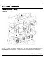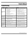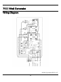
1
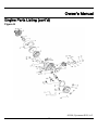
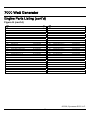
PREFACE
Thank you for purchasing products from SYCAMORE SCS, LLC. We appreciate your business.
The following manual is only a guide to assist you and is not a complete or comprehensive manual of
all aspects of maintaining and repairing your generator. The equipment you have purchased is a
complex piece of machinery. We recommend that you consult with a dealer if you have doubts or
concerns as to your experience or ability to properly maintain or repair your equipment. You will
save time and avoid the inconvenience of having to go back to the store if you choose to write or call
us concerning missing parts, service questions, operating advice, and/or assembly questions. Our
gasoline generators have some of the following features:
•
•
•
•
•
•
•
Lightweight construction
Air cooled, four stroke gasoline internal combustion engine
Recoil starter
Large, spark arrestor muffler
Circuit protector
AC Outlets
Low oil level sensor
Air-cooled gasoline generators are widely used when electrical power is scarce. Our generators
provide a portable solution in supplying power for field operations during project construction.
This manual will explain how to operate and service your generator set.
If you have any questions or suggestions about this manual, please contact your local dealer or us
directly. Consumers should notice that this manual might differ slightly from the actual
product as more improvements are made to our products. Some of the pictures in this manual
may differ slightly from the actual product as well.
© 2006, Sycamore SCS, LLC. - Rev. 1
7000 Watt Generator
Table of Contents
Table of Contents................................................................................................................................................. 2
Safety Guidelines – Definitions ............................................................................................................................ 4
Save These Important Safety Instructions! .................................................................................................. 4
General Precautions ............................................................................................................................................ 5
Carbon Monoxide ......................................................................................................................................... 5
Gasoline and Oil........................................................................................................................................... 5
Hot Components .......................................................................................................................................... 6
Power Output ............................................................................................................................................... 6
Work Area .................................................................................................................................................... 6
Electrical Safety............................................................................................................................................ 7
Personal Safety ............................................................................................................................................ 8
Generator Use and Care .............................................................................................................................. 9
Servicing....................................................................................................................................................... 9
Heart Pacemakers........................................................................................................................................ 9
Installation .................................................................................................................................................. 10
Mechanical ................................................................................................................................................. 11
Chemicals................................................................................................................................................... 11
Noise .......................................................................................................................................................... 12
Extension Cord........................................................................................................................................... 12
Assembly............................................................................................................................................................ 13
Wheel and Handle Assembly ..................................................................................................................... 13
Wheel Assembly......................................................................................................................................... 13
V-Leg Support Assembly............................................................................................................................ 13
Handle Assembly ....................................................................................................................................... 14
Specifications ..................................................................................................................................................... 15
General Parts Listing.......................................................................................................................................... 16
Figure A...................................................................................................................................................... 16
Generator Parts Listing ...................................................................................................................................... 18
Figure B...................................................................................................................................................... 18
© 2006, Sycamore SCS, LLC.
2
Owner's Manual
Panel Parts Listing ............................................................................................................................................. 19
Figure C...................................................................................................................................................... 19
Engine Parts Listing ........................................................................................................................................... 20
Figure D...................................................................................................................................................... 20
Figure E...................................................................................................................................................... 22
Figure F ...................................................................................................................................................... 23
Figure G ..................................................................................................................................................... 24
Figure H...................................................................................................................................................... 25
Installation .......................................................................................................................................................... 27
General Location ........................................................................................................................................ 27
Support and Mounting ................................................................................................................................ 28
Grounding................................................................................................................................................... 28
Operation ........................................................................................................................................................... 29
Before Starting the Generator .................................................................................................................... 29
Starting ....................................................................................................................................................... 30
Powering 120 Volt AC Tools and Equipment: ............................................................................................ 31
Inspection, Cleaning, and Maintenance ............................................................................................................. 32
Trouble Shooting................................................................................................................................................ 33
Wiring Diagram .................................................................................................................................................. 34
Compliance ........................................................................................................................................................ 35
Limited Warranty ................................................................................................................................................ 36
_________________________________________________________________________________________
WARNING! READ AND UNDERSTAND ALL SAFETY PRECAUTIONS IN THIS MANUAL
BEFORE OPERATING.
FAILURE TO COMPLY WITH INSTRUCTIONS IN THIS
MANUAL COULD RESULT IN PERSONAL INJURY, PROPERTY DAMAGE, AND/OR
VOIDING OF YOUR WARRANTY. SYCAMORE SCS WILL NOT BE LIABLE FOR ANY
DAMAGE BECAUSE OF FAILURE TO FOLLOW THESE INSTRUCTIONS.
© 2006, Sycamore SCS, LLC.
3
7000 Watt Generator
Safety Guidelines – Definitions
This manual contains important information that you need to know and understand in order to
ENSURE YOUR SAFETY and to PREVENT EQUIPMENT PROBLEMS. The following symbols help
you recognize this information. Please read the manual and pay attention to the notifications that
follow these symbols.
WARNING! WARNINGS INDICATE CERTAIN OR STRONG POSSIBILITY OF PERSONAL
INJURY OR DEATH IF INSTRUCTIONS ARE NOT FOLLOWED.
CAUTION: CAUTIONS INDICATE A POSSIBILITY OF EQUIPMENT DAMAGE IF
INSTRUCTIONS ARE NOT FOLLOWED.
Note: Notes give helpful information.
WARNING! IMPROPER OPERATION OR MAINTENANCE OF THIS PRODUCT COULD
RESULT IN SERIOUS INJURY AND PROPERTY DAMAGE. READ AND UNDERSTAND
ALL WARNINGS AND OPERATING INSTRUCTIONS BEFORE USING THIS EQUIPMENT.
WHEN USING POWER TOOLS, BASIC SAFETY PRECAUTIONS SHOULD ALWAYS BE
FOLLOWED TO REDUCE THE RISK OF PERSONAL INJURY.
Save These Important Safety Instructions!
Read and understand all of these safety instructions. Be sure to retain them for
future use.
© 2006, Sycamore SCS, LLC.
4
Owner's Manual
General Precautions
WARNING! FAILURE TO FOLLOW THESE INSTRUCTIONS CAN RESULT IN SEVERE
INJURY OR DEATH.
CAUTION: FAILURE TO FOLLOW THESE INSTRUCTIONS CAN ALSO RESULT IN
DAMAGE TO THE TOOL AND/OR THE ITEM YOU ARE WORKING ON.
Carbon Monoxide
When this tool is running, ensure that the area is well ventilated.
engine in an enclosed area without an exhaust evacuation system.
Never run the
WARNING! THE EXHAUST CONTAINS POISONOUS CARBON MONOXIDE GAS THAT
CAN CAUSE LOSS OF CONSCIOUSNESS AND MAY LEAD TO DEATH. CARBON
MONOXIDE IS KNOWN TO CAUSE CANCER, BIRTH DEFECTS, AND OTHER
REPRODUCTIVE HARM.
Gasoline and Oil
This product requires oil and fuel. Attempting to start the engine without oil will ruin
the engine and void the warranty. Work in well ventilated areas. Keep cigarettes,
flames, or sparks away from the work area or where gasoline is stored.
WARNING! GASOLINE IS EXTREMELY FLAMMABLE AND IS EXPLOSIVE UNDER
CERTAIN CONDITIONS. KEEP OUT OF REACH OF CHILDREN.
•
•
•
•
•
•
•
•
Gasoline fuel and fumes are flamm able and potentially explosive. Use proper fuel storage and
handling procedures. Always have multiple ABC class fire extinguishers nearby.
Keep the generator and surrounding area clean at all times.
Fuel or oil spills must be cleaned up immediately. Dispose of fluids and cleaning materials as
per any local, state, or federal codes and regulations. Store oily rags in a covered metal
container.
Never store fuel or other flammable materials near the generator.
Do not smoke or allow sparks, flames, or other sources of ignition around the engine or fuel tank.
Fuel vapors are explosive.
Keep grounded conductive objects such as tools away from exposed or live electrical parts and
connections to avoid sparking or arcing. These objects could ignite fumes or vapors.
Do not refill the fuel tank while the engine is running or while the engine is still hot. Do not
operate a generator with known leaks in the fuel system.
Use only the engine manufacturer’s recommended fuel and oil.
© 2006, Sycamore SCS, LLC.
5
7000 Watt Generator
General Precautions (cont'd)
Gasoline and Oil (cont'd)
•
Excessive buildup of unburned fuel gases in the exhaust system can create a potentially
explosive condition. This buildup can occur after repeated failed start attempts, valve testing,
or hot engine shutdown. If this occurs, open exhaust system drain plugs and allow the gases to
dissipate before attempting to restart the generator.
Hot Components
WARNING! ENGINE AND EXHAUST SYSTEM PARTS BECOME VERY HOT AND
REMAIN HOT FOR SOME TIME AFTER ENGINE SHUT OFF. WEAR INSULATED
GLOVES OR WAIT UNTIL THE ENGINE AND EXHAUST SYSTEM HAVE COOLED
BEFORE HANDLING THESE PARTS.
Power Output
This generator is not designed to power sensitive electronic equipment (including computers and
medical devices) without the addition of an approved line conditioner, which is sold separately.
CAUTION: ATTEMPTING TO POWER SENSITIVE ELECTRONIC EQUIPMENT WITHOUT
THE USE OF AN APPROVED LINE CONDITIONER MAY CAUSE DAMAGE TO THE
EQUIPMENT.
SYCAMORE SCS IS NOT RESPONSIBLE FOR ANY DIRECT OR
INDIRECT DAMAGE CAUSED BY FAILURE TO USE AN APPROVED LINE
CONDITIONER.
Work Area
•
Keep your work area clean and well lit.
accidents.
•
Do not operate power tools in explosive environments such as in the presence of flammable
liquids, gases, or dust. Generators create sparks which may ignite dust or fumes.
Keep bystanders, children, and visitors away while operating a generator. Provide barriers or
shields as needed.
•
Cluttered benches and dark areas invite
© 2006, Sycamore SCS, LLC.
6
Owner's Manual
General Precautions (cont'd)
Electrical Safety
•
Grounded tools must be plugged into an outlet, properly installed, and grounded in
accordance with all codes and ordinances. Never remove the grounding prong or
modify the plug in any way. Do not use any adapter plugs.
•
Grounding provides a low-resistance path to carry electricity away from the user in the event of
an electrical malfunction.
Double insulated tools are equipped with a polarized plug where one blade is wider than the
other. This plug fits into a polarized outlet in one way, only. If the plug does not fit fully in
the outlet, reverse the plug. If it still does not fit, contact a qualified electrician to install a
polarized outlet. Do not change the plug in any way. Double insulation eliminates the need
for a three-wire grounded power cord and a grounded power supply system.
Avoid body contact with grounded surfaces such as pipes, radiators, ranges, and refrigerators.
There is an increased risk of electric shock if your body is grounded.
Do not expose generator to rain or wet conditions. Water entering a generator will increase the
risk of electric shock.
Do not abuse the power cord. Keep power cords away from heat, oil, sharp edges, or moving
parts. Replace damaged power cords immediately. Damaged power cords increase the risk
of electric shock.
When operating a power tool outside, use outdoor extensions cords marked "W-A" or "W".
These extension cords are rated for outdoor use, and reduce the risk of electric shock.
All connections and conduits from the generator to the load must be installed by trained and
licensed electricians, only. Installations must be in compliance with all relevant local, state,
and federal electrical codes and standards, and other regulations where applicable.
For fixed installations, the generator must be earth-grounded before operation in accordance with
all relevant electrical codes and standards.
Do not attempt to connect or disconnect wires to the load while standing in water or on wet or
soggy ground.
Do not touch electrically energized parts of the generator and interconnecting cables or
conductors with any part of the body or with any non-insulated conductive object.
•
•
•
•
•
•
•
•
•
© 2006, Sycamore SCS, LLC.
7
7000 Watt Generator
General Precautions (cont'd)
Electrical Safety (cont'd)
•
•
•
•
Before servicing equipment powered by the generator, disconnect the equipment from its power
input.
Keep all electrical equipment clean and dry. Replace any wiring where the insulation is
cracked, cut, abraded, or otherwise degraded. Replace terminals that are worn, discolored, or
corroded. Keep terminals clean and tight.
Insulate all connections and disconnected wires.
Guard against electric shock. Prevent body contact with grounded surfaces such as pipes,
radiators, ranges, and refrigerators.
Personal Safety
•
Stay alert. Watch what you are doing and use common sense when operating a
generator. Do not use a generator while tired or under the influence of drugs,
alcohol, or medication. A moment of inattention while operating generators may
result in serious personal injury.
•
Dress properly. Do not wear loose clothing or jewelry. Contain long hair. Keep your hair,
clothing, and gloves away from moving parts. Loose clothes, jewelry, or long hair can be
caught in moving parts.
Avoid accidental starting. Make sure the power switch is in its "STOP" position and disconnect
the spark plug wire when not in use.
Remove adjusting keys or wrenches before turning on the generator. A wrench or a key that is
left attached to a rotating part of the generator may result in personal injury.
Do not overreach. Keep proper footing and maintain balance at all times.
Use safety equipment. Always wear eye protection. Wear ANSI approved safety impact eye
goggles. Dust masks, non-skid safety shoes, hard hats, or hearing protection must be used for
appropriate conditions.
Do not overload the generator. Use the appropriate generator for your application. The
correct generator working at the rate for which it is designed, will do the job better and safer.
Do not use the generator if the power switch does not turn the generator on or off. Any
generator that cannot be controlled by the power switch is dangerous and must be fixed or
replaced.
•
•
•
•
•
•
© 2006, Sycamore SCS, LLC.
8
Owner's Manual
General Precautions (cont'd)
Generator Use and Care
•
•
•
•
•
Make sure the power switch is in its "STOP" position and disconnect the spark plug wire before
making any adjustments, changing any accessories, or storing the generator. Such preventive
safety measures reduce the risk of starting the generator accidentally.
Store idle generators out of reach of children and other untrained persons. Generators are
dangerous in the hands of untrained users.
Maintain generators with care. Do not use a damaged generator. Tag damaged generators
"DO NOT USE" until repaired.
Check for misalignment or binding of moving parts, broken parts, and any other condition that
may affect the generator's operation. If damaged, have the generator serviced before using.
Many accidents are caused by poorly maintained generators.
Use only accessories that are recommended by the manufacturer for your model. Accessories
that may be suitable for one generator may become hazardous when used on another.
Servicing
•
•
•
Maintain labels and name plates on the generator and engine.
These carry important
information. If unreadable or missing, contact SYCAMORE SCS immediately for a replacement.
Generator servicing must be performed by qualified repair personnel only.
Service or
maintenance performed by unqualified personnel could result in a risk of injury.
When servicing a generator, use only identical replacement parts and follow all appropriate
instructions in this manual.
Use of unauthorized parts or failure to follow maintenance
instructions may create a risk of electric shock or injury.
Heart Pacemakers
WARNING! PEOPLE WITH PACEMAKERS SHOULD CONSULT THEIR PHYSICIAN(S)
BEFORE USING THIS PRODUCT.
ELECTROMAGNETIC FIELDS IN CLOSE
PROXIMITY TO A HEART PACEMAKER COULD CAUSE INTERFERENCE TO OR
FAILURE OF THE PACEMAKER.
© 2006, Sycamore SCS, LLC.
9
7000 Watt Generator
General Precautions (cont’d)
Installation
•
•
•
•
•
•
•
•
•
•
•
•
Ensure installation meets all applicable local and national safety and electrical codes. Have
installation performed by a qualified licensed electrician or building contractor.
All electrical work, including the earth-ground connection, should be completed by a licensed
electrician.
Any separate fuel storage or generator supply facility must be built or installed in full compliance
with all relevant local, state, and federal regulations.
It is recommended to use the generator only in well ventilated outdoor areas. A running
gasoline engine will generate carbon monoxide. This colorless and odorless gas can cause
serious injury or death if inhaled.
If the generator is installed indoors, exhaust fumes must be piped out of the building using
leak-free and heat resistant piping. Pipes and soundproofing insulation should not use any
flammable materials nor should they be installed near any flammable objects. Generator
exhaust fumes must be within legal limits and installation must always meet local building codes.
If the generator is installed outdoors, it must be weatherproofed and should be soundproofed.
It should not be run outdoors without adequate protection to the generator and wiring conduit.
The generator weighs approximately 235 lbs. Without mechanical aid, lifting the generator off
the ground will require two or more people. Never lift the generator using any part of the
engine or alternator.
Connect lifting equipment to the frame of the generator, only. Before lifting the generator with
equipment, ensure that the equipment and supporting structure are in good condition and are
rated to lift the intended load.
Keep all personnel away from the suspended generator during relocation.
The supporting floor or ground surface should be level and strong enough to safely hold the
weight of the generator. If the surface is not level, strong cross members should be placed
underneath the lower side of the generator frame. Ensure that cross members run the full
length of the generator frame.
For trailer installation, the generator should be mounted in the middle of the trailer and over the
wheels. The trailer must be capable of supporting the weight of the generator, accessories,
and all contents (tools, etc.).
Install weatherproofing and sound insulation only when it is not raining nor snowing to avoid
trapping moisture within the generator or within surrounding insulation.
© 2006, Sycamore SCS, LLC.
10
Owner's Manual
General Precautions (cont'd)
Mechanical
•
•
•
•
•
•
•
•
•
Always make sure the power switch is in its "STOP" position. Disconnect the spark plug wire
and allow the engine to completely cool before carrying out maintenance.
Check for damaged parts. Before using the generator, any part that appears damaged should
be carefully checked to determine that it will operate properly and perform its intended function.
Check for alignment and binding of moving parts, any broken parts or cracked mounting fixtures,
and any other condition that may affect proper operation.
The generator is designed with safety guards for protection against contact with moving parts.
In any case, care must still be taken to protect personnel and equipment from other mechanical
hazards when working in the vicinity of the generator.
Do not operate the generator without safety guards. While the generator is running, do not
attempt to reach around the safety guard for maintenance or any other reason.
Keep hands, arms, long hair, loose clothing, and jewelry away from moving parts. Be aware
that when engine parts are moving fast they cannot be seen clearly.
Keep access doors closed and locked when access to the generator is not required.
When working on or in the vicinity the generator, always wear protective clothing including ANSI
approved safety gloves, safety eye goggles, and safety hats.
Do not alter or adjust any part of the generator that is assembled and supplied by the
manufacturer.
Always follow and complete scheduled engine and generator maintenance.
Chemicals
•
•
Avoid contact with hot fuel, oil, exhaust fumes, and hot solid surfaces.
Avoid body contact with fuels, oils, and lubricants used in the generator. If swallowed, seek
medical treatment immediately. If fuel is swallowed, do not induce vomiting. For skin contact
with fuel, immediately wash with soap and water. For eye contact with fuel, immediately flush
eyes with clean water and seek medical attention.
© 2006, Sycamore SCS, LLC.
11
7000 Watt Generator
General Precautions (cont'd)
Noise
Prolonged exposure to noise levels above 85 dB is hazardous to hearing. Always wear ANSI
approved ear protection when operating or working around the generator while it is running.
Extension Cord
If an extension cord (not included) is required, make sure to use only UL approved cords.
should have the correct gauge and length according to the following table:
Cords
Cord Lengths
Nameplate Amps (@ full load)
0'·50'
50'·100'
100'·150'
150'·200'
0-5
16
16
12
12
5.1 - 8
16
14
10
-
8.1 - 12
14
12
-
-
12.1 -15
12
10
-
-
15 - 20
10
10
-
-
© 2006, Sycamore SCS, LLC.
12
Owner's Manual
Assembly
Wheel and Handle Assembly
Confirm that the following sub-assembly components are included:
•
•
•
•
•
•
1
2
4
2
1
2
•
•
•
•
•
Wheel Axle
Heavy Duty Wheels
Large Washers
Cotter Pins
Front Stand-off Support V-Leg
Support V-Leg Mounting Screws
1
1
1
3
3
Handle
Handle Mounting Bracket
Back Plate (Mounting Bracket)
Hinge Bolt Mounting Nuts
Three Inch Mounting Bolts
Wheel Assembly
Perform the following tasks to install the heavy duty wheels onto the generator assembly:
1. Insert axle through brackets located on the bottom cross bar of the frame.
2. Center axle in frame and place each wheel over each end of the axle, then insert axle end into the
hole located in the center of the wheel hub.
3. Place each large washer over the axle ends and insert axle through center of washer until washer
is flush against wheel hub.
4. Insert straight side of cotter pin into one of the holes located at both ends of the axle rod and
thread the cotter pin through the hole until pin snaps into place.
5. Repeat using the second cotter pin on the opposite end of the axle to secure the opposite wheel
to the axle assembly.
V-Leg Support Assembly
Perform the following tasks to install the V-leg support bracket:
1. Align V-leg support mounting holes with the mounting holes on the bottom of the frame.
2. Insert one mounting bolt completely through each mounting hole.
3. Twist mounting screws to catch the threads in the frame mounting holes and weld nuts and tighten
until support leg is secure.
© 2006, Sycamore SCS, LLC.
13
7000 Watt Generator
Assembly (cont'd)
Handle Assembly
Perform the following tasks to install the handle onto the generator frame:
1. On the side of frame with mounting holes, place back plate in the middle of handle bracket and
frame. Handle bracket should have handle mounting holes facing downward.
2. Align frame, back plate and handle bracket mounting holes.
3. Insert one mounting bolt through handle bracket, back plate, frame, and into mounting nut.
Twist mounting nut lightly.
4. Insert the second mounting bolt through the second mounting hole. Twist mounting nut until nut,
frame, back plate, and handle bracket surfaces are flush.
5. Return to first nut and tighten.
6. Align handle mounting holes with mounting holes on handle bracket.
7. Insert mounting bolt completely through handle and bracket.
8. Install a mounting nut onto bolt and tighten. Make sure handle can swivel.
© 2006, Sycamore SCS, LLC.
14
Owner's Manual
Specifications
Electrical
Current Output
120-240VAC @ 50/25A, 60Hz 12V DC
Continuous/Rated Wattage
6,000
Peak Wattage
8,000
Outlets
two 120V 20A outlets
one 120V 30A twist lock outlet
one 120V/240V 30A twist lock outlet
one 12V DC outlet
Gasoline Engine
Horsepower
13HP
Type
4-cycle OHV air-cooled recoil start
Displacement
389cc
Oil Capacity
1.16 quart (1.1 liter)
EPA Approved
yes
Type
unleaded gasoline
Capacity
5.5 gallons (21 liters)
Running Time
7 hours (approx.)
Fuel Gauge
included
Approximate Weight
235 lbs
Operating Noise Level
76 dB (approx.)
Fuel
Weight
Noise Level
© 2006, Sycamore SCS, LLC.
15
7000 Watt Generator
General Parts Listing
Figure A
This list is provided for reference purposes only. All repairs and part replacement should be
performed by a qualified technician. Some parts may not be available as single replacements.
© 2006, Sycamore SCS, LLC.
16
Owner's Manual
General Parts Listing (cont’d)
Figure A (cont’d)
ITEM
NO.
A01
1
ITEM
NO.
A38
A02
1
A39
A03
PSYCG7000EA03
4
A40
HEX NUT M8
PSYCG7000EA04
4
A41
BACK PLATE
PSYCG7000EA41
1
SPRING WASHER Ø8.2 x Ø16
PSYCG7000EA05
4
A42
FLAT WASHER Ø8.2 x Ø13
PSYCG7000EA42
2
SOCKET HEAD BOLT M8 x 30
PSYCG7000EA06
4
A43
TOP COVER
HEX BOLT M8 x 248
PSYCG7000EA07
1
A44K
A08
BOWL WASHER Ø9 x Ø17.5
PSYCG7000EA08
1
A44
A09
NUT M8
PSYCG7000EA04
1
A45
A10
ALTERNATOR
PSYCG7000EA10
1
A46
A11
FLANGED NUT M6
PSYCG7000EA11
1
A47
WASHER Ø6.6 x Ø22
PSYCG7000EA47
4
A12
SCREW M6 x12
PSYCG7000EA12
1
A48
FLANGED BOLT M6 x20
PSYCG7000EA48
4
A13
MUFFLER
PSYCG7000EA13
1
A49
FUEL TANK
PSYCG7000EA49
1
A14
DOUBLE SIDED M8 x 25 SCREW
PSYCG7000EA14
2
A50
FILTER NET
PSYCG7000EA50
1
A15
HEX NUT M8 x 13
PSYCG7000EA15
2
A51
FUEL TANK CAP GASKET
PSYCG7000EA51
1
A16
SPRING WASHER Ø8.2 x Ø13
PSYCG7000EA16
4
A52
FUEL TANK CAP
PSYCG7000EA52
1
A17
MUFFLER GASKET
PSYCG7000EA17
2
A53
FUEL GAUGE
PSYCG7000EA53
1
A18
MUFFLER CONNECT PIPE
PSYCG7000EA18
1
A54
FUEL COCK
PSYCG7000EA54
1
A19
RUBBER PAD
PSYCG7000EA19
2
A55
BACK COVER
PSYCG7000EA55
1
A20
FLANGED BOLT M8 x 14
PSYCG7000EA20
2
A56
LEFT COVER
PSYCG7000EA56
1
A21
BOTTOM FOOT
PSYCG7000EA21
1
A57
WHEEL
PSYCG7000EA57
2
A22
FLANGED NUT M8
PSYCG7000EA22
2
A58
WASHER Ø16.2 x Ø30
PSYCG7000EA58
4
A23
FRONT COVER
PSYCG7000EA23
1
A59
SPLIT PIN Ø3 x 25mm
PSYCG7000EA59
2
A24
FLANGED BOLT M5 x 8
PSYCG7000EA24
24
A60
AXLE
A25
BATTERY
NA
1
A61K
PSYCG #
QTY
ENGINE 13HP
PSYCG7000EA01
FLANGE
PSYCG7000EA02
SOCKET HEAD BOLT M10 x 25
A04
A05
A06
A07
A26K
DESCRIPTION
PSYCG #
QTY
ACORN NUT M8
PSYCG7000EA38
1
HANDLE BRACKET
PSYCG7000EA39
1
HEX SOCKET SCREW M8 x 60
PSYCG7000EA40
2
PSYCG7000EA43
2
PSYCG7000EA44K
1
NUT FLANGED M6
PSYCG7000EA11
4
BUSHING
PSYCG7000EA45
4
RUBBER GASKET
PSYCG7000EA46
4
TANK MOUNTING KIT (Includes A44-48)
FUEL TUBE KIT (Includes A61 & 62)
PSYCG7000EA60
1
PSYCG7000EA61K
1
PSYCG7000EA26K
1
A61
FUEL TUBE
PSYCG7000EA61
1
A26
TIE DOWN HOOKS
PSYCG7000EA26
2
A62
CLAMP
PSYCG7000EA62
2
A27
BATTERY TIE DOWN
PSYCG7000EA27
1
A63
STARTER
PSYCG7000EA63
1
A28
WING NUT M6
PSYCG7000EA28
2
A64
STARTER SOLENOID
PSYCG7000EA64
1
PSYCG7000EA29
4
A65
SMALL FLANGED BOLT M6 x 8
PSYCG7000EA65
6
A29
A30K
BATTERY TIE DOWN KIT (A26-28)
DESCRIPTION
ISOLATOR (RUBBER MOUNT)
ISOLATOR BOLT KIT (Includes A29-A33)
PSYCG7000EA30K
1
A66
MUFFLER COVER
PSYCG7000EA66
1
HEX BOLT M10 x 25
PSYCG7000EA30
4
A67
HEX BOLT M10 x 40
PSYCG7000EA67
2
A31
WASHER Ø10.2 x Ø20
PSYCG7000EA31
12
A68
ACORN NUT M10
PSYCG7000EA68
2
A32
SPRING WASHER Ø10.2 x Ø16
PSYCG7000EA32
8
A69
MUFFLER INSULATION BOARD
PSYCG7000EA69
1
HEX NUT M10
PSYCG7000EA33
8
A70
WASHER Ø6.6 x Ø15.5
PSYCG7000EA70
2
NA
1
A71
HANDLE GRIP
PSYCG7000EA71
1
PSYCG7000EA35
1
A72
FLAT SCREW M6 x10
PSYCG7000EA72
2
A30
A33
A34
FRAME
A35
RIGHT COVER
A36
SOCKET BOLT M8 x 55
A37K
A37
HANDLE BRACKET KIT (Includes A38-42)
HANDLE
PSYCG7000EA36
1
A73
SPRING WASHER Ø8.2 x Ø13
PSYCG7000EA16
1
PSYCG7000EA37K
1
A74
FLAT WASHER Ø8.2 x Ø13
PSYCG7000EA42
8
PSYCG7000EA37
1
© 2006, Sycamore SCS, LLC.
17
7000 Watt Generator
Generator Parts Listing
Figure B
ITEM
NO.
B01
B02
B03
B04
B05
B06
B07
B08
B09
B10
B11
B12
B13
B14
B15
B16
DESCRIPTION
COOLING FAN
ROTOR
DIODE
Ø 32 WASHER
Ø 32 CLAMP
BEARING
DRIVE END BRACKET
ENCLOSING BAND
STATOR
ALTERNATOR BACK COVER
HEX BOLT M8 x 210
WASHER Ø 8.2 x ф16
CAPACITOR SHELF
OVAL HEAD BOLT M5 x 8
CAPACITOR 24-28 μƒ
CAPACITOR FASTENER
PSYCG #
QTY
PSYCG7000EB01
PSYCG7000EB02
PSYCG7000EB03
PSYCG7000EB04
PSYCG7000EB05
PSYCG7000EB06
PSYCG7000EB07
PSYCG7000EB08
PSYCG7000EB09
PSYCG7000EB10
PSYCG7000EB11
PSYCG7000EB12
PSYCG7000EB13
PSYCG7000EB14
PSYCG7000EB15
PSYCG7000EB16
1
1
4
1
1
1
1
1
1
1
4
4
1
1
1
2
ITEM
NO.
B17
B18
B19
B20
B21
B22
B23
B24
B25
B26
B27
B28
B29
B30
B31
DESCRIPTION
ALTENATOR COVER
OVAL HEAD BOLT M5 x 12
SCREW M8 X 250mm
WASHER Ø 8mm
NUT M8
OVAL HEAD BOLT M6 x 14
WASHER Ø7mm
REGULATOR
OVAL HEAD BOLT M5 x 8
REGULATOR SHELF
SPRING WASHER Ø8.2 x Ø13
DIODE FRAME
RUBBER PAD
GROUND PLATE
OVAL HEAD BOLT M5 x 6
PSYCG #
QTY
PSYCG7000EB17
PSYCG7000EB18
PSYCG7000EB19
PSYCG7000EB20
PSYCG7000EA04
PSYCG7000EB22
PSYCG7000EB23
PSYCG7000EB24
PSYCG7000EB25
PSYCG7000EB26
PSYCG7000EA05
PSYCG7000EB28
PSYCG7000EB29
PSYCG7000EB30
PSYCG7000EB31
1
4
2
1
1
2
2
1
2
1
4
1
2
1
1
© 2006, Sycamore SCS, LLC.
18
Owner's Manual
Panel Parts Listing
Figure C
ITEM
NO.
C01
C02
C03
C04
C05
C06
C07
C08
C09
C10
C11
C12
C13
C14
C15
C16
C17
C18
C19
DESCRIPTION
CIRCUIT BREAKER 20A WITH NUT
BREAKER 20A NUT
CIRCUIT BREAKER 25A WITH NUT
BREAKER 25A NUT
OVAL HEAD BOLT ST4 x 10
AMP METER
VOLT METER
SPRING WASHER Ø3.2x Ø 5
HEX NUT M3
FLANGED BOLT M6 x 18
CONTROL PANEL
KEY
STARTER SWITCH NUT
STARTER SWITCH WITH NUT
HOUR METER W/ BRACKET AND NUT
HOUR METER BRACKET
HOUR METER NUT
GROUND BOLT M8 x 20
NEGATIVE DC PORT
PSYCG #
QTY
PSYCG7000EC01
PSYCG7000EC02
PSYCG7000EC03
PSYCG7000EC02
PSYCG7000EC05
PSYCG7000EC06
PSYCG7000EC07
PSYCG7000EC08
PSYCG7000EC09
PSYCG7000EC10
PSYCG7000EC11
PSYCG7000EC12
PSYCG7000EC13
PSYCG7000EC14
PSYCG7000EC15
PSYCG7000EC16
PSYCG7000EC17
PSYCG7000EC18
PSYCG7000EC19
2
2
2
2
2
1
1
8
8
4
1
1
1
1
1
1
1
1
1
ITEM
NO.
C20
C21
C22
C23
C24
C25
C26
C27
C28
C29
C30
C31
C32
C33
C34
C35
C36
C37
DESCRIPTION
DC FUSE
POSITIVE DC PORT
HEX NUT M4
SPRING WASHER Ø4.2 Xø6
WASHER Ø4..2 xØ10
OVAL HEAD SCREW M4X12
4 PRONG SOCKET NEMA L14-30
3 PRONG SOCKET NEMA L5-30
DUPLEX SOCKET NEMA L5-20
CONTROL PANEL BOX
OUTLET TRAP
WIRING HARNESS
FIBER WASHER Ø6.2 xØ12
WASHER Ø3.2 xØ7
OVAL HEAD BOLT M4 x 10
DECORATIVE CUPREM NUT M8
HEX CUPREM NUT M8
CUPREM WASHER Ø8.2 xØ16
PSYCG #
QTY
PSYCG7000EC20
PSYCG7000EC21
PSYCG7000EC22
PSYCG7000EC23
PSYCG7000EC24
PSYCG7000EC25
PSYCG7000EC26
PSYCG7000EC27
PSYCG7000EC28
PSYCG7000EC29
PSYCG7000EC30
PSYCG7000EC31
PSYCG7000EC32
PSYCG7000EC33
PSYCG7000EC34
PSYCG7000EC35
PSYCG7000EC36
PSYCG7000EC37
1
1
6
6
6
6
1
1
1
1
1
1
4
8
4
1
1
3
© 2006, Sycamore SCS, LLC.
19
7000 Watt Generator
Engine Parts Listing
Figure D
© 2006, Sycamore SCS, LLC.
20
Owner's Manual
Engine Parts Listing (cont’d)
Figure D (cont’d)
ITEM
NO.
D01
D02
D03
D04
D05
D06
D07
D08
D09
D10K
D10
D11
D12
D13
D14
DESCRIPTION
PSYCG #
QTY
KNURL HEAD SCREW M5X20mm
AIR FILTER COVER
GASKET
AIR FILTER B
ELEMENT FITTING PLATE
M6 FLANGE NUT
PLATE
AIR FILTER CASE
CHOKE AIR VALVE
GASKET KIT (Includes D10, 12, 13, 14)
INLET GASKET
CARBURETOR
CARBURETOR GASKET
CARBURETOR INSULATOR
INSULATOR GASKET
PSYCG7000ED01
PSYCG7000ED02
PSYCG7000ED03
PSYCG7000ED04
PSYCG7000ED05
PSYCG7000EA11
PSYCG7000ED07
PSYCG7000ED08
PSYCG7000ED09
PSYCG7000ED10K
PSYCG7000ED10
PSYCG7000ED11
PSYCG7000ED12
PSYCG7000ED13
PSYCG7000ED14
1
1
1
1
1
2
1
1
1
1
1
1
1
1
1
ITEM
NO.
D15
D16
D17
D18
D19
D20
D21
D22
D23
D24
D25
D26
D27
D28
DESCRIPTION
STUD BOLT M8 XM6x108
AIR PIPE CLIP
AIR PIPE A 14cm
UNILATERAL VALVE
AIR PIPE B 9cm
M5 FLANGED NUT
M6 FLANGED NUT
BRACKET
GASKET
PAN HEAD SCREW M5X15
PAN HEAD SCREW M6X15
AIR FILTER C
PAN HEAD SCREW M5X15
AIR FILTER A
PSYCG #
QTY
PSYCG7000ED15
PSYCG7000ED16
PSYCG7000ED17
PSYCG7000ED18
PSYCG7000ED19
PSYCG7000ED20
PSYCG7000EA11
PSYCG7000ED22
PSYCG7000ED23
PSYCG7000ED24
PSYCG7000ED25
PSYCG7000ED26
PSYCG7000ED24
PSYCG7000ED28
2
4
1
1
1
6
1
1
1
1
1
1
6
1
© 2006, Sycamore SCS, LLC.
21
7000 Watt Generator
Engine Parts Listing (cont’d)
Figure E
ITEM
NO.
E01
E02
E03
E04
E05
E06
DESCRIPTION
KEY 4 x 13
CRANK
FLANGED BOLT M8 x38
CONNECTING ROD CAP
CONNECTING ROD
PISTON PIN
PSYCG #
QTY
PSYCG7000EE01
PSYCG7000EE02
PSYCG7000EE03
PSYCG7000EE04
PSYCG7000EE05
PSYCG7000EE06
1
1
2
1
1
1
ITEM
NO.
E07
E08
E09K
E09
E10
E11
DESCRIPTION
PISTON PIN CIRCLIP
PISTON
RING KIT (E9, 10, 11)
OIL RING
2ND COMPRESSION RING
1ST COMPRESSION RING
PSYCG #
QTY
PSYCG7000EE07
PSYCG7000EE08
PSYCG7000EE09K
PSYCG7000EE09
PSYCG7000EE10
PSYCG7000EE11
2
1
1
1
1
1
© 2006, Sycamore SCS, LLC.
22
Owner's Manual
Engine Parts Listing (cont’d)
Figure F
ITEM
NO.
F01
F02
F03
F04
F05
F06
F07
F08
DESCRIPTION
CLAMP
PAN HEAD SCREW M5 X35
SPRING
REGULATING SPRING
LINK ROD
GOVERNOR ARM
SQUARE HEAD BOLT M6
WASHER Ø8.2 Xø16
PSYCG #
QTY
PSYCG7000EF01
PSYCG7000EF02
PSYCG7000EF03
PSYCG7000EF04
PSYCG7000EF05
PSYCG7000EF06
PSYCG7000EF07
PSYCG7000EF08
1
1
1
1
1
1
1
1
ITEM
NO.
F09
F10
F11
F12
F13
F14
F15
DESCRIPTION
COVERNOR SHAFT CLIP
COVERNOR SHAFT
FLANGED NUT M6
BACK SPRING
AIR FLOW COVER
FLANGED BOLT M6 x 12
OIL SEAL GOVERNOR SHAFT
PSYCG #
QTY
PSYCG7000EF09
PSYCG7000EF10
PSYCG7000EA11
PSYCG7000EF12
PSYCG7000EF13
PSYCG7000EF14
PSYCG7000EF15
1
1
1
1
1
3
1
© 2006, Sycamore SCS, LLC.
23
7000 Watt Generator
Engine Parts Listing (cont’d)
Figure G
ITEM
NO.
G01
G02
G03
G04
G05
G06
G07
G08
G09
G10
DESCRIPTION
CYLINDER HEAD GASKET
INTAKE VALVE
CYLINDER HEAD
EXHAUST VALVE BUSHING
VALVE SPRING
INTAKE VALVE RETAINER
EXHAUST VALVE RETAINER
SPARK PLUG
LOCATING RING
EXHAUST VALVE
PSYCG #
QTY
PSYCG7000EG01
PSYCG7000EG02
PSYCG7000EG03
PSYCG7000EG04
PSYCG7000EG05
PSYCG7000EG06
PSYCG7000EG07
PSYCG7000EG08
PSYCG7000EG09
PSYCG7000EG10
1
1
1
1
2
1
1
1
2
1
ITEM
NO.
G11
G12
G13
G14
G15
G16
G17
G18
G19
G20
DESCRIPTION
PUSH ROD
PUSH ROD GUIDE
ROCKER SCREW
VALVE ROCKER ARM
ADJUSTER
M6 x0.75 NUT
FLANGED BOLT 10x1.25x80-8.8
AIR FLOW GUIDE
FLANGED BOLT M6 x12
OIL SEAL INTAKE
PSYCG #
QTY
PSYCG7000EG11
PSYCG7000EG12
PSYCG7000EG13
PSYCG7000EG14
PSYCG7000EG15
PSYCG7000EG16
PSYCG7000EG17
PSYCG7000EG18
PSYCG7000EF14
PSYCG7000EG20
2
1
2
2
2
2
4
1
1
1
© 2006, Sycamore SCS, LLC.
24
Owner's Manual
Engine Parts Listing (cont’d)
Figure H
© 2006, Sycamore SCS, LLC.
25
7000 Watt Generator
Engine Parts Listing (cont’d)
Figure H (cont’d)
ITEM
NO.
H01K
H01
H02
H03
H04
H05
H06
H07
H08
H09
H10
H11
H12
H13
H14
H15
H16
H17
H18
H19
H20
H21
H22
H23K
H23
H24
ITEM
NO.
H25
H26
H27
H28
H29
H30
H31
H32
H33
H34
H35
H36
H37
H38
H39
H40
H41
H42
H43
H44
DESCRIPTION
PSYCG #
QTY
PSYCG7000EH01K
PSYCG7000EH01
PSYCG7000EH02
PSYCG7000EH03
PSYCG7000EH04
PSYCG7000EH05
PSYCG7000EH06
PSYCG7000EH07
PSYCG7000EH08
PSYCG7000EH09
PSYCG7000EH10
PSYCG7000EH11
PSYCG7000EH12
PSYCG7000EA42
PSYCG7000EH14
PSYCG7000EH15
PSYCG7000EH16
PSYCG7000EH17
PSYCG7000EF14
PSYCG7000EH19
QT
Y.
1
3
1
1
1
1
4
1
1
1
2
1
1
1
1
1
1
1
2
2
RING SEAL
CRANKCASE COVER
OIL SEAL Ø52 x Ø35 x 8
FLANGED BOLT M8 x 40
CYLINDER HEAD GASKET
INSIDE SHEILD
CYLINDER HEAD COVER
GAS PIPE
HEAD COVER BOLT M6 x 60
FLANGED BOLT M6 x 12
II DA
RUBBER BAND
FLANGED BOLT M6 x 12
BRACKET
FLANGED BOLT M6 x 25
ELECTRIC MAGNET
ENGINE HOLE COVER
BEARING 6202
BALANCER SHAFT
FLANGED BOLT M6 x 12
PSYCG7000EH25
PSYCG7000EH26
PSYCG7000EH27
PSYCG7000EH28
PSYCG7000EH29
PSYCG7000EH30
PSYCG7000EH31
PSYCG7000EH32
PSYCG7000EH33
PSYCG7000EF14
PSYCG7000EH35
PSYCG7000EH36
PSYCG7000EF14
PSYCG7000EH38
PSYCG7000EH39
PSYCG7000EH40
PSYCG7000EH41
PSYCG7000EH42
PSYCG7000EH43
PSYCG7000EF14
2
1
1
7
1
1
1
1
1
1
1
1
1
1
2
1
3
2
1
3
LOCATING RING
PSYCG7000EH20
2
H45
AIR FLOW GUIDE
PSYCG7000EH45
1
CAMSHAFT
VALVE LIFTER
GEAR CASE SEAL KIT (Includes H23 & 27)
CRANK CASE GASKET
OIL LEVEL PLUG
PSYCG7000EH21
PSYCG7000EH22
PSYCG7000EH23K
PSYCG7000EH23
PSYCG7000EH24
1
2
1
1
1
H46
H47
H48
H49
CYLINDER HEAD RUBBER WASHER
WASHER Ø6 x Ø10
OIL CAP
HEAD COVER WASHER
PSYCG7000EH46
PSYCG7000EH47
PSYCG7000EH48
PSYCG7000EH49
1
1
1
1
DESCRIPTION
PSYCG #
PULL START ASSEMBLY (H01-04)
FLANGED BOLT M6 x 18
RECOIL STARTER
HEX NUT M16 x 1.5
STARTER PULLEY
FAN COVER
FLANGED BOLT M6 x 12
FLYWHEEL FAN
FLYWHEEL
IGNITION COIL
BOLT M6 x25
OIL SEAL Ø52 x Ø35 x 8
SPEED REGULATING WHEEL
FLAT WASHER Ø8.2 x Ø13
CRANKCASE
FLANGED BOLT M12 x 16
WASHER Ø 17
OIL SENSOR
FLANGED BOLT M6 x 12
CRANK CASE BEARING 6207
© 2006, Sycamore SCS, LLC.
26
Owner's Manual
Installation
Note: Prior to powering tools and equipment, make sure the generator's rated voltage,
wattage, and amperage capacity (120-240VAC @ 50/25AMPs) is adequate to supply all
electrical loads that the unit will power. If powering exceeds the generator's capacity,
it may be necessary to group one or more of the tools and/or equipment for connection to
a separate generator.
Electrical and other permits may be required for the installation of emergency power systems.
Investigate your local building and electrical codes before installing this unit. Installation must be
completed by licensed contractors.
WARNING! THE GENERATOR WEIGHS APPROXIMATELY 235 POUNDS. USE CARE
WHEN LIFTING. ENSURE USE OF THE PROPER HOISTING OR LIFTING EQUIPMENT
WHEN MOVING IT TO THE INSTALLATION LOCATION. ALWAYS CONNECT LIFTING
LINES TO THE FRAME OF THE GENERATOR.
General Location
•
•
•
•
•
•
Make sure to locate and install the generator outdoors where air for cooling is readily available.
Install the generator so that the air inlets and outlets are not blocked by obstructions such as
bushes, trees, or snow drifts. Locating it in the path of heavy winds or snowdrifts may require
the placement behind a barrier for protection. In normal weather conditions, the air vent should
face the prevailing wind direction.
Install the generator on a raised concrete slab or other area where rain drainage or flood waters
cannot reach it.
Consider maintenance requirements when installing. Generator placement should allow for four
feet of access to all sides of the unit for maintenance purposes.
Place the generator as close as possible to the electrical tools and equipment being powered to
limit the need for and reduce the length of extension cords.
If the generator is located indoors, the engine exhaust must be ventilated to the outdoors using
leak-proof, heat resistant, and flexible tubing.
© 2006, Sycamore SCS, LLC.
27
7000 Watt Generator
Installation (cont'd)
Support and Mounting
Mount the generator on a concrete slab capable of supporting the weight of the generator and any
accessories. The slab must extend beyond all sides of the frame by at least one foot. Contact a
cement contractor for slab specifications if necessary. Attach the frame to the concrete slab using
⅜ inch diameter expansion anchor bolts (not supplied).
Grounding
Note: It is recommended that only a trained and licensed electrician perform this
procedure.
Connect a #6 AWG grounding wire (not included) from the ground connector on the generator (C18 on
the control panel) to a grounding rod (not included) that has been driven at least 24 inches deep into
the earth. The grounding rod must be an earth-driven copper or brass rod (electrode) which can
adequately ground the generator.
© 2006, Sycamore SCS, LLC.
28
Owner's Manual
Operation
Note: The parts listings above are helpful fo r locating the controls mentioned below.
CAUTION: PRIOR TO USING THE GENERATOR SET FOR THE FIRST TIME, THE
ENGINE MUST BE FILLED WITH APPROXIMATELY ¾ QUART OF A HIGH QUALITY SAE
10W-30 GRADE ENGINE OIL. TO DO SO, UNSCREW AND REMOVE THE ENGINE'S
OIL LEVEL PLUG (DIPSTICK) LOCATED AT THE BOTTOM OF THE ENGINE
CRANKCASE. FILL THE ENGINE'S CRANKCASE UNTIL THE OIL LEVEL READING IS
AT THE UPPER MARKED LINE ON THE OIL LEVEL PLUG. DO NOT OVERFILL OIL.
TO FINISH, SCREW THE OIL LEVEL PLUG BACK INTO THE OIL FILL HOLE.
Before Starting the Generator
1. Check that the generator power switch
(“START SWITCH”) is in its "STOP"
position.
2. Before the first use, remove the fuel tank
cap and fill the fuel tank with unleaded
gasoline. When fueling, be sure that the
fuel strainer is in place. Replace the fuel
tank cap and check the engine's fuel
gauge for the amount of unleaded gasoline
in the fuel tank. If necessary, refill the
fuel tank with unleaded gasoline.
The
generator must be turned off and cooled
down before refilling the fuel tank.
3. Before each use, check oil and fill if
needed.
© 2006, Sycamore SCS, LLC.
29
7000 Watt Generator
Operation (cont’d)
Starting
1. Make sure that all tools and equipment to be powered by the generator are not plugged into the
unit while the engine is started.
2. Open the fuel valve. Turn lever to the “ON” position.
3. Close the choke lever by turning it to the “START” position
(about ⅛ inch clearance)
4. Turn the key clockwise to the “RUN” position
5. Handle start:
Hold the start handle loosely and pull it slowly several
times to allow the gasoline to flow into the engine's
carburetor. Then hold the start handle firmly and pull the
rope hard and fast. Pull the rope all the way out using
two hands if needed. If necessary, repeat several times
until the engine starts.
6. Electric starter:
Turn the key clockwise to the “START” position and return
the key to the “RUN” position once the engine has started.
Do not use the starter for more than 5 seconds at a time.
If the engine fails to start, release the switch and wait 10
seconds before operating the starter again.
7. BATTERY (optional: for units with electric starters, only):
Batteries contain electrolyte fluid or battery acid.
Batteries emit hydrogen gases during charging.
The
slightest spark will ignite hydrogen and cause an
explosion.
Note: The customer is responsible for purchasing a battery
for the unit. The battery capacity is at 28Ah~36Ah.
8. Allow the engine to run for several seconds.
lever to the “RUN” position.
Then open choke all the way by turning choke
© 2006, Sycamore SCS, LLC.
30
Owner's Manual
Operation (cont'd)
Powering 120 Volt AC Tools and Equipment:
1. Prior to connecting tools and equipment, make sure the generator's rated voltage, and amperage
capacity (120-240VAC @ 50/25AMPs) is adequate to supply all electrical loads that the unit will
power. If powering exceeds the generator's capacity, it may be necessary to group one or more
of the tools and/or equipment for connection to a separate generator.
CAUTION: ATTEMPTING TO POWER SENSITIVE ELECTRONIC EQUIPMENT WITHOUT
THE USE OF AN APPROVED LINE CONDITIONER MAY CAUSE DAMAGE TO THE
EQUIPMENT.
SYCAMORE SCS IS NOT RESPONSIBLE FOR ANY DIRECT OR
INDIRECT DAMAGE CAUSED BY FAILURE TO USE AN APPROVED LINE
CONDITIONER.
2. Once the generator is running, simply connect the power cords of 110/120 volt AC powered tools
and equipment into the 110/120 volt AC dual outlets.
Note: The generator features an AC Non-Fuse Circuit Breaker to protect the AC circuit in
case of an overload. Should an overload occur, the breaker will “trip” to its off position
causing the generator to automatically shut down. In this case, refer to Step #1 above
in this section. Then, reset the circuitry system by turning the circuit breaker to its on
position.
Restart the generator and continue powering the remaining tools and
equipment.
3. When finished using the generator, turn the start switch to its "STOP" position. Turn the fuel
valve to its “OFF” position.
4. Disconnect all electrical powered tools and equipment from the generator's 110/120 volt AC duel
outlets.
5. After the engine and generator have completely cooled, store generator in a safe, clean, and dry
location (if not already installed).
© 2006, Sycamore SCS, LLC.
31
7000 Watt Generator
Inspection, Cleaning, and Maintenance
WARNING! ALWAYS MAKE SURE THE GENERATOR POWER SWITCH IS IN ITS
“STOP" POSITION. DISCONNECT THE SPARK PLUG WIRE FROM THE ENGINE AND
ALLOW SUFFICIENT TIME FOR THE ENGINE AND GENERATOR TO COMPLETELY
COOL BEFORE PERFORMING ANY INSPECTIONS, MAINTENANCE, OR CLEANING.
•
Before each use, inspect the generator.
-
•
•
•
•
•
•
•
Check for:
Loose screws
Misaligned or binding moving parts
Cracked or broken parts
Damaged electrical wiring, or
Any other condition that may affect safe operation.
If an engine problem occurs, have it checked by a qualified service technician before further use.
Do not use damaged equipment.
Before each use, make sure the engine's oil and gas levels are adequate. If necessary, fill the
crankcase until the oil level is even with the oil fill hole or at the upper level on the oil level cap.
Also fill the gas tank with gas until the fuel gauge shows full.
Before each use, remove all debris with a soft brush, rag, or vacuum.
Lubricate all moving parts using premium quality and lightweight machine oil.
Every 20 hours of use, drain old engine oil and
replace with approximately ¾ quart of high quality
SAE 10W-30 grade engine oil.
DO NOT
OVERFILL OIL.
Every 300 hours of use, have a qualified and
certified technician perform thorough maintenance
on the generator and engine.
For long term storage, either drain fuel into a
suitable
container
or
add
a
fuel
preservative/stabilizer (not included) to prevent
fuel breakdown.
© 2006, Sycamore SCS, LLC.
32
Owner's Manual
Trouble Shooting
Problem
Engine will not start
or runs rough when
started.
Cause
Solution
1.
2.
3.
4.
5.
6.
7.
8.
9.
10.
11.
12.
13.
1.
2.
3.
4.
5.
6.
7.
8.
9.
10.
11.
12.
13.
Generator switch set to "STOP".
Fuel valve is in the “OFF” position.
Dirty air cleaner.
Out of gasoline.
Bad gasoline.
Loose or disconnected spark plug wire.
Bad spark plug.
Water in gasoline.
Over choking.
Low oil level.
Excessive rich fuel mixture.
Intake valve stuck open or closed.
No compression.
Set switch to "RUN".
Turn fuel valve to the “ON” position.
Clean or replace air cleaner.
Fill fuel tank.
Drain gas tank and fill with fresh fuel.
Connect wire to spark plug.
Replace spark plug.
Drain gas tank; fill with fresh fuel.
Close choke. Set to “START” position.
Fill crankcase to proper level.
Contact your local service dealer.
Contact your local service dealer.
Contact your local service dealer.
Engine is running but
No AC output.
1. Circuit breaker open.
2. Connected device is faulty.
3. The capacitor or the diode is damaged.
1. Reset circuit breaker.
2. Connect a device in good condition.
3. Change the capacitor or diode.
Engine runs but gets
bogged down when
loads are connected.
1.
2.
3.
4.
1.
2.
3.
4.
Engine lacks power.
1. Load is too high.
2. Dirty air filter.
3. Engine needs to be serviced.
1. See "Operation" section.
2. Replace air filter.
3. Contact your local service dealer.
1. Out of gasoline.
2. Problem with engine.
1. Fill fuel tank.
2. Contact your local service dealer.
1. Choke is opened too soon.
2. Carburetor is running too rich or too lean.
1. Move choke to halfway position till engine
runs smoothly.
2. Contact your local service dealer.
Engine shuts down
during operation.
Engine hunts or
surges.
Electrical short is present.
Generator is overloaded.
Engine speed too low.
Generator circuit shorted.
Disconnect shorted electrical load.
Refer to "Operation" section.
Contact your local service dealer.
Contact your local service dealer.
© 2006, Sycamore SCS, LLC.
33
7000 Watt Generator
Wiring Diagram
© 2006, Sycamore SCS, LLC.
34
Owner's Manual
Compliance
UNITED STATES ENVIRONMENTAL PROTECTION AGENCY, WASHINGTON, DC 20460
2005 Model Year Certificate of Conformity
•
•
•
•
Manufacturer: Ningde CUE Electrical and Machinery CO., LTD.
Certificate Number: CUE -NRSI-05-02
Effective Date: 3/10/2005
Date Issued: 3/10/2005
Merrylin Zaw-Mon, Director, Certification and Compliance Division, Office of Transportation and Air
Quality.
Pursuant to Section 213 of Clean Air Act (42 U.S.C. section 7547) and 40 CFR 90, and subject to the
terms and conditions prescribed in those provisions, this certificate of conformity is hereby issued for
the following small non-road engine family, more fully described in the documentation required by 40
CFR 90 and produced in the stated model year.
This certificate of conformity covers only those new small non-road engines which conform in all
material respects to the design specifications described in the documentation required by 40 CFR 90
and which are produced during the model year stated on this certificate. This certificate of
conformity does not cover small non-road engines imported prior to the effective date of the
certificate.
This certificate of conformity is conditional upon compliance of said manufacturer with the averaging,
banking, and trading provisions of 40 CFR Part 90, Subpart C both during and after model year
production. Failure to comply with these provisions may render this certificate void ab initio. The
HC +NOX family emission limit (FEL) is: g/k W-hr.
It is a term of this certificate that the manufacturer shall consent to all inspections described in 40
CFR 90.126 and 90.506 and authorized in a warrant or court order. Failure to comply with the
requirements of such a warrant or court order may lead to revocation or suspension of this certificate
for reasons specified in 40 CFR 90. It is also a term of this certificate that this certificate may be
revoked or suspended or rendered void ab initio for other reasons specified in 40 CFR 90.
This certificate does not cover small non-road engines sold, offered for sale, introduced, or delivered
for introduction into commerce in the U.S. prior to the effective date of the certificate.
© 2006, Sycamore SCS, LLC.
35
7000 Watt Generator
Limited Warranty
SYCAMORE SCS warrants to the original purchaser who uses the product in a consumer application
(personal, residential or household usage) that all products covered under this warranty are free from
defects in material and workmanship for two years from the date of purchase. All products covered
by this limited warranty which are used in commercial applications (that is, income producing
applications) are warranted to be free of defects in material and workmanship for 90 days from the
date of original purchase. Products covered under this warranty include air compressors, air tools,
service parts, pressure washers, and generators.
SYCAMORE SCS will repair or replace, at SYCAMORE SCS's sole option, products or components
which have failed within the warranty period. Service will be scheduled according to the normal
work flow and business hours at the service center location and the availability of replacement parts.
All decisions of SYCAMORE SCS with regard to this limited warranty shall be final.
This warranty gives you specific legal rights and you may also have other rights which vary from
state to state.
RESPONSIBILITY OF ORIGINAL PURCHASER (initial user):
•
To process a warranty claim on this product, DO NOT return item to the retailer. The product
must be evaluated by an Authorized Warranty Service Center. For the location of the nearest
Authorized Warranty Service Center contact SYCAMORE SCS at 1-800-801-2051.
•
Retain original cash register sales receipt as proof of purchase for warranty work. Purchaser
must complete the product registration form and return to SYCAMORE SCS with proof of
purchase within 90 days of purchase.
•
Use reasonable care in the operation and maintenance of the product as described in the
Owner’s Manual(s).
•
Deliver or ship the product to the nearest Authorized Warranty Service Center.
any, must be paid by the purchaser.
•
If the purchaser does not receive satisfactory results from the Authorized Warranty Service
Center, the purchaser should contact SYCAMORE SCS.
Freight costs, if
© 2006, Sycamore SCS, LLC.
36
Owner's Manual
Limited Warranty (cont'd)
THIS WARRANTY DOES NOT COVER:
•
•
Merchandise sold as reconditioned, used as rental equipment, or used as floor or display models.
Merchandise that has become damaged or inoperative because of ordinary wear or misuse;
exposure to cold, heat, rain, or excessive humidity; use of improper chemicals, negligence,
accidents, or failure to operate the product in accordance with the instructions provided in the
Owners Manual(s) supplied with the product; improper maintenance; the use of accessories or
attachments not recommended by SYCAMORE SCS; unauthorized repair or alterations.
•
•
Repair and transportation costs of merchandise determined not to be defective.
Costs associated with assembly, required oil, adjustments, or other installation and start-up
costs.
•
Expendable parts or accessories supplied with the product which are expected to become
inoperative or unusable after a reasonable period of use.
•
Merchandise sold by SYCAMORE SCS which has been manufactured by and identified as the
product of another company, such as gasoline engines. The product manufacturer's warranty, if
any, will apply.
© 2006, Sycamore SCS, LLC.
37
7000 Watt Generator
Limited Warranty (cont’d)
•
ANY INCIDENTAL, INDIRECT OR CONSEQUENTIAL LOSS, DAMAGE, OR EXPENSE THAT MAY
RESULT FROM ANY DEFECTS, FAILURE OR MALFUNCTION OF THE PRODUCT IS NOT
COVERED BY THIS WARRANTY. SOME STATES DO NOT ALLOW THIS EXCLUSION, SO IT
MAY NOT APPLY TO YOU.
•
IMPLIED WARRANTIES, INCLUDING THOSE OF MERCHANTABILITY OR FITNESS FOR A
PARTICULAR PURPOSE, ARE LIMITED TO ONE YEAR FROM THE DATE OF ORIGINAL
PUCHASE. SOME STATES DO NOT ALLOW LIMITATIONS ON HOW LONG AN IMPLIED
WARRANTY LASTS, SO THE ABOVE LIMITATIONS MAY NOT APPLY TO YOU.
SYCAMORE SCS, LLC
12540 Westport Rd. Ste. 2
Louisville, KY 40245
Ph (800) 801-2051
(502) 292-4850
© 2006, Sycamore SCS, LLC.
38