1
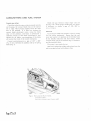
SUPPLEMENTARY INFORMATIONT
FOR
4'2 LITRE
ccB.,
TYPE AND 2+2 CARS
(sERrES
2)
This Supplement covers the variations between the
4.2 Litre (Series 2) ss¡tt Type,212 (Series 2) and
the 3.8 Litre versions of the ttEtt Type. Insert the
Supplement at the end of the 3.8 Litre "E" Type
Seryice Manual, Publication No. E.123.
:
ISSUED BY
JAGU,4,R CARS LIMITED,
Tclcphone
2221 (P.B.X.)
ALLESLEY
COVENTRY,
Code
I]ENTLEY'S SECOND
Publication No. El56ll
ENGLAND
Tclegraphic Addres
"JAGUÀR", COVENTRY Tetcx Jt622
INDEX TO SECTIONS
SECTON TITLE
GENERAL INFORMATION
CARBURETTERS AND
COOLING SYSTEM
EY
FY
AUTOM,ATIC TRANSMISSION
FFY
FRONT SUSPENSION
JY
REAR AXLE
HY
IY
(POWER-ASSISTED)
IIY
LY
WHEELS AND TYRES ..
MY
BODY AND EXHAUST SYSTEM
NY
HEATING AND WINDSCREEN WASHER
OY
ELECTRICAL AND INSTRUMENTS
EXHAUST EMISSION CONTROL
AIR.CONDITIONING REFRIGERATION EQUIPMENT
RY
SECT¡OF.¡ A
GENERAL INFORMAT¡Oh¡
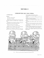
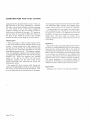
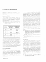
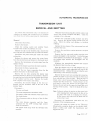
The Routine Maintenance Service periods have been
increased to 3,000 mile (5,000 km.) stages as follows:-
1,000 MILES (1,600 KM.)
1.
2.
3.
FREE SERVICE
Road test and check for oil, petrol, hydraulic
fluid or cooiant leaks.
Check torque loading of cylinder head nuts.
Checkoilorfluidlevelsandtopupas necessary:-
(a) Brake reservoirs,
(b) Clutch reservoir (if fitted),
(c) Power steering reservoir (if fitted),
(d) Top up carburetter hydraulic dampers and
check carburation,
(e) Battery,
(f)
Screen washer bottle,
(g) Radiator header tank (add anti-freeze when
necessary),
(h) Manual gearbox,
(i) Final drive unit.
4,
Drain and refill
5.
(a) Engine sump,
(b) Automatic transmission unit (if fitted).
Actjust front band on automatic transmission
unit (if fitted).
Check driving belts for correct tension.
6.
7.
8.
9.
10.
11.
12.
13.
14.
15.
Clean and adjust contact-breaker points.
Check all brake pipe unions, petrol pipe unions,
and hoses for leakage.
Check tightness of all front and rear suspension
bolts and nuts.
Cheok tightness ofnuts on all steering connections
including colurnn universal joints.
Check tightness of road wheel nuts and wheel
alignment.
Check tyres for damage and adjust pressures.
Check operation of all lights and systems.
Check door locks and bonnet release control,
Lubricate all grease nipples (excluding wheel
bearings).
Page AY.s.1
3,000 MILES (5,000 KM.)
CHECK SERVICE
Repeat these servicing items at the under-mentioned
subsequent periods:9,000 miles (15,000 Km.)
15,000 miles (25,000 Km.)
21,000 miles (35,000 Km.)
27,000 miles (45,000 Km.)
33,000 mileS (55,000 Km.)
39,000 miles (65,000 Km,)
45,000 mileS (75,000 Km.)
51,000 miles (85,000 Km.)
57,000 miles (95,000 Km.)
63,000 miles (105,000 Km.)
69,000 miles (115,000 Km.)
l
Check oil or fluid levels and top up as necessary
(a) Engine sump,
:-
(b) Brake reservoirs,
(c) Clutch reservoir (if fitted),
(d) Power steering reservoir (if fitted),
(e) Top up carburetter hydraulic dampers and
check carburation,
(f)
Battery,
1g) Screen washer bottle,
(h) Radiator header tank (add anti-freeze
when necessary),
gearbox,
(i) Manual
2.
3.
4.
5.
fi) Final drive unit.
Check driving belts for correct tension.
Examine brake pads for wear and check operation
of brake stop lights.
Examine tyres for damage and adjust pressures.
Check tightness of road wheel nuts.
6,000 MILES (10,000 KM.)
MINOR SERVICE
:
Repeat these servicing items at the under-mentioned
Subsequent periods:18,000 miles (30,000 Km.)
30,000 miles (50,000 Krn.)
42,000 miles (70,000 Km.)
54,000 miles (90,000 Km.)
66,000 miles (110,000 Km.)
1
.
Check oil or fluid levels and top up as necessary
(a) Brake reservoirs,
(b) Clutch reservoir (if fitted),
(c) Power steering reservoir (if fitted),
:-
(d) Top up carburetter dampers,
(e) Battery and check connections,
,
(f)
2.
3.
+.
5.
6.
7.
Screen washer bottle,
(e) Radiato¡ header tank (add anti-freeze
when necessary),
Fage AY.s.2
8.
(h) Manual gearbox or automatic transmission
unit,
(i) Final drive unit.
Drain and refill:(a) Engine sump. Fit new oil filter elffnent
and seal.
Check driving belts for correct tension.
Check brake pads for wea¡ and advise wear-rate
to owner.
Check tyres for damage and tread depth. If
uneven wear evident, check wheel alignment.
Adjust pressures.
Check tightness of road wheel nuts.
Check headlamp alignment and functioning of
mandatory lights including stop lights.
Lubricate all grease nipples, excluding wheel
bearings.
MrLES (20,000 KM.)
II{AJOR SERVICE
12,000
Repeat these servicing items at the under_mentioned
subsequent periods:24,000 miles (40,000 Km.)
48,000 miles (80,000 Km.)
60,000 miles (100,000 Km.)
L
Check oil or fluid levels and top up as necessary
(a) Brake reservoirs,
5.
:_
9.
10.
I
Screen washer bottle,
(g) Radiator header tank (add anti_freeze
13.
(i) Final drivsunir.
Drain and refill:(a) Engine sum.p.
and seal,
Fit
1,
new oil filter element
14.
lights
including stop lights and alignment of heádlamps,
Check tyres for damage and tread depth. If
uneven wear evident, check wheel alignment.
Adjust pressures.
Oil can lubrication of door locks, bonnet hinges
and locks, boot hinges and lock, seat slides, fuel
(b) Manual gearbox. Clean overdrive filter (if
filler flap hinges, control linkages.
fitted),
15. Detect and report any oil, petrol, water, hydraulic
fluid leakage and damaged hoses or other
(c) Final drive unit (if .powr_Lok, differential
3.
4.
Check driving belts lor wear and tension.
Adjust top timing chain if required.
Lubricate all grease nipples including front
and
rear wheel bearings.
Check all suspension and exhaust mountings
for
security.
Check all steering connections, ball joints etc.,
for security and wear.
Check brake pads f.or degree of wear and advise
wear-rate to owner.
12. Check functioning of all mandatory
when necessary),
(h) Autornatic transmission,
2.
Lubricate distributor.
6.
7.
8.
(b) Clutch ¡eservoir (if fitted),
(c) Power steering reservojr (if fitted),
(d) Top up carburetter hydraulic aalp..s,
(e) Battery and check connections,
(f)
Clean and adjust contact breaker points.
Check
of centrifugal advance mechanism.
operation
fitted. Use only special Umited slip oil).
Renew sparking plugs.
damaged parts,
Renew air cleaner element and fuel line filter
element.
36,000 MrLES (60,000 KM.)
MÀIOR SERVICE
Repeat these servicing items at the under_mentioned
subsequent
5.
period:-
14000 miles (120,000 Km.)
I
.
Check oil or fluid levels and top up as necessary
'6.
7.
E.
:_
(a) Clutch reservoir (if fitred),
(b) power steering reservoir (if fitted),
(c) Top up carburetter hydraulic daÁpers,
(d) Battery and check connections,
(e) Screen washer bottle,
(f) Radiator header tank (add anti_freeze
9.
10.
when necessary),
2.
(g) Automatic transmìssion,
(h) Final drive uni
Drain and refill:(a) Engine sump. Fit new oil filter element
and seal,
(b) Manual gearbox. Clean overdrive filter (if
firted),
3.
4.
(c) Braking system. Retract wheel cylinder
prstons to expell all old fluid,
(d) Final drive unir (if .powr_Lok, differential
f,tted. Use only special iimited slip oil).
Renew sparking plugs
Renew
element.
air cleaner element and fuel line filter
I
L
12.
Clean and adjust contact breaker points. Check
operation of centrifugal advance mechanism.
Lubricate distributor.
Check driving belts for wear and tension.
Adjust top timing chain if required.
Lubricate all grease nipples including front and
rear wheel bearings.
Check all suspension and exhaust mounting for
security.
Check all steering connections, balljoints etc., for
security and wear.
Check brake pads for degree of wear and advise
wear-rate to ownei.
Check functioning of all mandatory lights
including stop lights and alignment olheadlamps.
13. 'Check tyres for damage and tread d.epth. If
74.
15.
uneven wear evident, check wheel alignment.
Adjust pressures.
Oil can lubrication of door locks, bonnet hinges
and lock, boot hinges, and lock, seat slides, fuel
filler flap hinges, control linkages.
Detect and report any oil, petrol, water, hydraulic
fluid leakage and damaged hoses or other
damaged parts.
Page AY.s.3
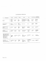
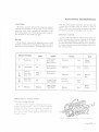
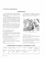
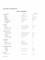
RECOMMENDED LUBRICANTS
MOBIL
Component
CASTROL
Mobil
Super or
Engine
Mobil
Special
Upper cylinder
lubrication
Distributo¡ oil can
ooihts
bil
can lubrication
Gearbox
Final Drive Unit
(not'Powr-Lok')
Mobil.,
{
I
J
uppeiluoe
3iÏ"'
or
U.C.L'
U.C.L.
Castrol
Shell
Super
Esso Extra
oil
Motor Oil
zowl40
HYPoY
Spirax
90 EP
Esso Gear Oil
GP 90/140
Castrolease
Retinax
GTX
Mobilube
Castrol
90
åï'0"
Shelt
Moto¡
10W/30
Esso Exira Motor
oil 20w/40
Oii
castrollo
Mobiloil
A
GX
Esso Extra
Shell
B.P.
ESSO
SHELL
Esso
DUCKHAM
e2o-so
or
SuPer
ViscoStatic
."15-1r1ll.
lóü",Ïä"
low/40
e55oo
u.c.L.
Adcoid
Liquid
Regent
Q20-50
30
Hypoid
Lubricant
Donax U.
Energol
SAE
30
Gear Oil
c^E
90 EP
90
iòwl¡o
U.C'L.
Havoline
Muitigear
EP.9O
Front wheel bearings
Rear wheel bearings
Distributor cam
Final drive half-shafts
LM
Steering tie-rods
Wheei swivels
Door hinges
Steering housing
Automatic
transmission unit
Power steering system
Page AY.s.4
Mobilfluid
200
Castrol
T.Q,
A
Shell
Donax
T6
Esso
Multi-purpose
Grease
H
Esso
Automatic
Transmission
Fluid
Energrease
L.2
LB
10
Automatic
$;ar-r;mission
Type A
Nolmatic
Marfak
All
PurPose
Texamatic
Fluid
SECTION
B
ENGINE
DATA
Q¡msheft
'004" to '006'(.10 to .15 mm.)
Permissible end float
Connecting Rod
Big end-Diameter clearance
to '0033'(.037 to .083 mm,)
'0015o
Crankshaft Main Boarings
2'750' to 2.7505' (69.85 to 69.86 mm.)
1$'(39.06 mm.)
1å'
+ .001' (34.37 mm. *
-'0005"
.025 mm.)
-'0125
mm.
-Reâr
-Intermediate
llft" I.O02' (30.96 mm. +
.05 mm.)
Cylinder Block
Bore size for fitting liners
3.761' ta 3.762"
(94.03
Outside diameter of liner
3.765' to 3.766'
(94'13 to 94.15 mm.)
.003"
Overall length of liner
to 94.05 mm,)
to .005' (.08 to
6'959" to 6,979' (17.39
.13 mm.)
to
17.45 cm.)
ENGINE
Piston and Piston Rings
Gudgeon pin
Piston
..
bore
rings-Width Compression
Oil Control
.
.
Piston rings-Thickness
'8571'to '8753" (2'188 to 2'1883 mm.)
'0770' to'0780' (l'97 to 2'@ mm.)
Self expanding (Maxiflex)
'151"
to '158" (3'775 to 3'95 mm.)
Piston rings-Gap when fitted to cylinder bore
Oil Control
Page BY.s.2
'015" to '033" ('38 to '82 mm.)
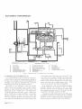
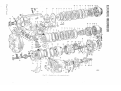
E
NGI NE
L
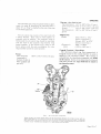
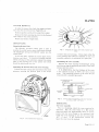
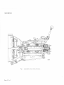
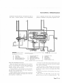
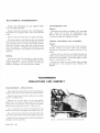
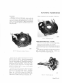
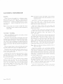
Cross sectional
rie*'ol
the engine.
Page BY.s.3
ENGI N E
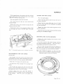
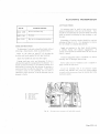
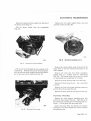
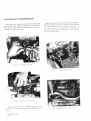
ENGINE REMOVAL AND REF¡TTING
REMOVAL
Remove the revolution counter generator complete
Remove the bonnet.
with
Disconnect the battery.
Drain the cooling system and cylinder block;
conserve the coolant if antifreeze is in use.
Slacken the clip on the breather pipe; unscrew the
two wing nuts and withdraw the top of the air cleaner.
Disconnect the petrol feed pipe from under the
centre carburetter.
Slacken the clamps and remove the water hoses
from the cylinder head and radiator to the header tank.
Slacken the two clamps and withdraw the water pump
hose. Remove the heater hoses from the inlet
manifold.
Disconnect the brake vacuum hose from the inlet
manifold.
Pull off the two Lucar connectors from the fan
thermostat control in the header tank.
Remove the two bolts securing the header tank
mounting bracket to the front cross member. Remove
the two nuts and two bolts securing the header tank
straps to the radiator and fan cowl. Withdraw the
header tank complete with mounting bracket and
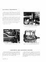
Disconnect
the throttle linkage at the
rear
carburetter.
Disconnect:The two coil leads.
The water temperature transmitter.
The battery cabie and solenoid switch cable
from the starter.
'
exhaust downpipe from the manifold. Unclip the
pipes at the silencers and withdraw the downpipes.
Collect the sealing rings between the pipes and the
manifold.
On standard transmission cars, proceed as follows:Remove the seats. Remove the knob and locknut
from the gear lever. Remove two hexagon headed
setscrews and two chromium-plated nuts and detach
the radio/ash tray console panel from the gearbox
tunnel. If a radio is fitted,
disconnect the electrical
cables from the control head to enable the panel to be
completely removed.
On2l2
cars, raise the central
arm-rest;lift out the
bottom panel; withdraw five self-tapping screws and
remove the central arm-rest. Lift off the trimmed
cover panel from the gearbox tunnel.
On all other cars, withdraw two pan-headed screws
and two seat belt attachments before lifting off the
trimmed cover. Withdraw the self-tapping screws
and remove the gearbox cover.
Disconnect the reverse lamp cables from the switch
straps.
,
cables.
Remove the four nuts and washers securing each
on the gearbox top cover.
Disconnect the speedometer drive cable from the
gearbox.
Remove the clutch slave operating cyiinder from
the clutch cover.
Disconnect the propeller shaft.
The output cables from the alternator.
On automatic transmission cars, proceed as follows:'Withdraw the t¡ansmission dipstick and unscrew
The engine earth strap from the left hand side
the dipstick tube from the transmission oil pan.
member.
Place the selector lever
in L and, from underneath
Withdraw the oil filter canister; catch the escaping
oil in a drip tray.
the car, unscrew the nut securing the selector cable
adjustable ball joint to the transmission lever. Release
Remove the crankshaft pulley, damper and drive
the nut securing the outer cable clamp to the abutment
bracket.
belt. Mark the pulley and damper to facilitate refìtting. Remove the ignition timing pointer from the
sump,
Page BY.s.4
Remove the speedometer drive cable
transmission extension housing.
from
the
ENGINE
Disconnect the transmission oil cooler pipes from
the right hand side of the radiator block and from the
transmission
unit,
Withdraw the clips and remove
the pipes.
Disconnect the kickdown cable at the rear of the
cylinder head.
Remove the central arm-rest and lift offthe trimmed
cover panel from the gearbox tunnel. Withdraw the
drive screws securing the cover plate on the trans_
mission tunnel. Disconnect the propeller shaft.
new bolts must be fitted and the torsion bars
re-set.
Support the engine by means of two individual
lifting tackles using the hooks provided on the cylinder
head. Insert a trolley jack under the transmission
(or gearbox) and support the transmission.
Remove the self-locking nut and washer from the
engine stabiliser.
Remove the bolts securing the rear engine mounting
engine
plate. Remove the bolts from the front
mountings.
For all models, proceed as follows:_
Remove the nuts securing the torsion bar reaction
tie plate on each side and tap the bolts back flush with
the face of the tie plate. With the aid of a helper,
place a lever between the head of the boltjust released
and the torsion bar. Exert pressure on the bolt head
to release the tension on the upper bolt. Remove the
nut and tap the upper bolt back flush with the face of
Raise the engìne on the lifting tackles and, keeping
the combined engine and transmission assembly level,
move forwards ensuring that the water pump pulley
clears the sub-frame
raise the front
and upwards.
top cross member. Carefr_rlly
of tbe engine and r.vithdraw forwards
REFITTING
Refitting is the reverse of the removal procedure.
After the unit is in place, it is important that the engine
the tie plate. Withdraw the bolts securing the tie
plate on each side to the body underframe ihannels
through the side members. Tap the tie plate off the
four bolts.
stabiliser is adjusted and that the clutch slave cylinder
is mounted correctly.
Note: Failure to relieve the tension on the upper bolts
when tapping them back to the tie plate will
result in stripping the threads. If this occurs,
On automatic transmission2] 2 cars, the kickdown
cable must be adjusted and the manual linkage
connected in accordance with the instructions given
in Section FF.
Page BY.s.S
ENGINE
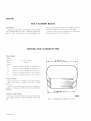
THE CYLINDER BLOCK
OVERÉIAUL
Reboring is normally recommended when the bore
wear exceeds '006" ('15 mm). Reboring beyond the
limit of .030' ('76 mm) is not
recommended and,
when the bores will not clean out at '030" ('76 mm),
liners anci standard size pistons should be fitted.
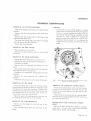
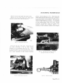
The worn liners must be pressed out from below
utilising the stepped block illustrated.
PISTONS AND GUDGEON PINS
Piston Grades
Gracie
Identification
To suit cylinder
3'75
bore size
(93.25mm
Letter
F
.G
,H
J
K
3'6250' to 3'6253" (92'015 to 92'0826 mm.)
3'6254' ro 3'6257" (92'0852 to 92'0928 mm.)
3'6258' to 3'6261" (92'0953 to 92'1029 mm.)
3'6262" to 3'6265" (92'1055 to 92'l 13l mm.)
3'6266' to 3'6269" (92'1156 ro 92'l123 mm.)
Oversize Pistons
Oversize pistons are available in the following sizes:
+.010" l'25 mm.) +'020' ('51 mm.) +'030"
( 76 mm.).
There are no selective grades in oversize pistons as
grading is necessaty purely for factory production
methods.
3'ozcitso'5mm)-]
I
Tapered Periphery Rings
All engine units are fitted with tapered periphery
piston rings and these must be fitted the correct way
up.
Page BY.s.6
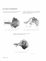
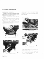
i32rrl
Fig.
2.
Stepped block
for
c-t'linder
lintt t ettntal.
ENGINE
The narrowest part of the ring must be fitted upper-
most; to assist in identifying the narrowest face a
ietter "T" or "Top" is marked on the side of the ring
to be fitted uppermost.
Ring gapwhen fitted to bore
Top compression .015'to .020" (.38 to .51 mm.)
Lowercompressìon.010" to .015" (.254 To,3g mm.)
Scraper
'015" 1o.045" (.38 to 1.143 mm.)
Side clearance in .00i " to .003" (.02 to .07 mm.)
groove
The oil control ring consists of two steel rails with
a spacer between. These rails are held together on
assembly with an adhesive. The expander, which is
fitted inside the oil cont¡ol ring, should be assembled
with the ends of the expander ring (internal ring)
butted together. If the internal ring is fitted to the
piston groove with the ends overlapping, the outer
Gudgeon Pins
Grades
Clearance in
plston
(Red) '8753" to .8154"
(22'23 to 22.24 mm.)
(Green) .8752" to .8753"
(22.22 to 22.23 nm.)
'0001" 1o.0003"
(.0025 to .0076 mm.)
ring assembly cannot be seated properly.
Cargraph Treatment-Fiston Rings
The chromium plated ring (top compression) is
Cargraph treated on the outside diameter to assist in
Pistons
Skirt clearance
'0007" to '0013' (.0 ì 8 to .03 mm.)
(measured at
bottom of skirt at
to gudgeon pin
pin axis)
90
bedding in the chromium surface. This coating is
coloured Red for identification purposes and should
not be removed. Excess oil or grease may be removed
with clean paraffin but rings should mt be soakerl in
any degreasing agent.
ftßmn'¡
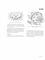
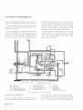
Fig.
3.
The titning gear arrongenrcnt.
when f,.tting a new lower timing chain, set the in¡ermediate damper (A)
in light contact with the
chain *'hen there is a r" (l mmr !ap between rtr. irùu.r rìip;;;;;'iih.'t;;riånl"i
uo¿y. In rhe case
of a worn chain.'Ser
the san rB) ma:y have ro be ¡ncreãse¿ i"'í*i¿ lã,1ìì";il;;;;; rhe chain
and rhe
cvlinder block.
rËe rower aímpèr tcr ir riúiri-ãåìru.t wirh rhe chain.
Page BY.s.7
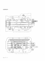
ENGINE
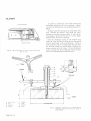
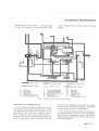
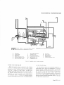
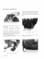
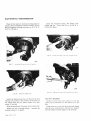
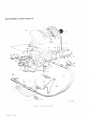
Fig.4. Longittnlinal settìott ttf tltc
olL
enginc
SUMP
REMOVAL
Drain the sump; disconnect the oil return pipe and
end and withdraw forward.
remove the crankshaft damPer.
REFITTING
Remove the self-locking nut and washer from the
top of the engine stabiliser. Screw down the lower
flanged washer to the limit of the stud thread.
Sling the engine from the rear lilting loop and raise
the engine approximately l" (25'4 mm.).
Refitting is the reverse of the removal procedure but
care must be taken to ensure that the rear oil seal is
positioned correctly. Adjust the engine stabiliser
Remove the sump securing screws, lower the lront
Page BY.s.8
after refitting.
Check for oil leakage after refilling the sump and
running the engine.
E
NGI NE
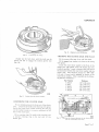
VALVE GUIDES
Valve guides have circlips fitted to ensure positive
location in the cylinder head. These valve guides
are chamfered at the upper ends and have the outside
diameter reduced at the lower end
"lead-in" when fitting.
to provide a
Oil seals are also fitted to the inlet valve guidea second groove being machined in the guide above
the circlip groove to seat the oil seal.
Checking Valve Guides
Examine the guides for evidence of wear in the bore.
The clearance between the valve stem and the guide
when new is '001"-.004" ('025-.10 mm).
If it is found necessary to renew worn valve guides,
they must be fitted in accordance with the following
instructions and only genuine factory replacement
parts used.
Valve Guide-Replacement
Heat the cylinder head by immersing in boiling
water for 30 minutes. With a piloted drift, drìve out
the old valve guide from the cornbustion chamber end.
Note: If carbon deposits around the valve guide in the
combustion chamber are quite heavy, they
be
cleaned off thoroughly before
attempting to drive out the old valve guide.
should
The valve guide (2) wiil be identified by the
machining of one circular groove on the shank of the,
guide: valve guide (l) will not have the groove.
When removing worn guides, care must be taken to
identify each individual guide to its particular bore iq.
the cylinder head.
Replacement guides are ayailable in the following
.
sizes and will have identification g¡ooves machined in
the shank as noted:I st oversize
'503" to .504"
(one groove)
(12.776 to 12.801 mm.)
2nd oversize
.506" fo.501"
(two grooves)
(12'852 to 12.877 mm.)
.511" to.512"
3rd oversize
(three grooves) (12.979 to 13.005 mm.)
Valve guides with one groove should only be fltted
as replacements for those originaly fitted without a
groove: the bore in the cylinder head will not require
reaming before fitting.
Guides with two grooves should be used as replace_
ments for those with one groove and guides with three
grooves
fòr those with two. Cylinder head bores
should be reamed
Valve Guide
'n,.,;J"^"'
to the following dimensrons:_
.s05"1'333;., ez.az,,'1,3å3
ii.ì
.5r0'l'333; (tz.ss'-" 1.3å3
ii l
grooves)
"t;Jå"'"
grooves)
Valve guides when fitted during engine assembly are
to the following dimensions and may be fltted in
mixed form.
(l) .501" r.o.502" (12.70 r.o 12.725 mm.)
(2) .503'to .504" (12.'176 ro 12.801 mm.)
Ream to Size
',,
Coat the valves with graphite grease and fit the
circlips. Reheat the cylinder head. With a piloted
drift, drive in the valve guide from the top until the
cirolip registers in the groove machined in the guide
bore of the cylinder head. Visually check that the
circlip has seated correctly.
Page BY.s,9
sEcTtoN c
CARBU RETTERS
CÄRBURETTERS
SYSTEM
washers together with the three gaskets.
Disconnect the throttle linkage
Removal
Drain the cooling
AND FUEL
at the rear
car-
buretter.
system.
Remove the three banjo union bolts and six fibre
Disconnect the battery.
washers from the float chambers.
Slacken the hose clip securing the water hose from
the inlet manifold to the header tank. Remove the
hose.
Ensure that the three float chamber filters are not
mislaid.
Disconnect the mixture control outer and inner
Disconnect the two electrical connections from the
thermostat fan control in the header tank.
Remove the throttle return springs,
Unclip hose connection to breather pipe.
Remove the two butterfly nuts at the carburetter
trumpets and remove the air cleaner elbow.
Remove the carburetter trumpet lrom the car_
buretters having ¡emoved the six nuts and spring
Fig.
I.
cables.
Remove the suction pipe from the front carburetter.
Disconnect the brown/black cable from the oil
pressure switch.
Slacken the clips and disconnect the heater pipes at
the water manifold and below the inlet manifold.
On 2-12 cars fitted with automatic transmission,
disconnect the kickdown cable at the rear of the
cylinder head.
Refitting the mìxture connol rods with the jet levers against the stops.
Page CY.s.1
CARBURETTERS
AND FUEL
SYSTEM
Remove the inlet manifold complete with
the
carburetters and linkage.
Remove the four nuts and spring washers, together
with the return spring bracket from each carburetter'
Remove all three carburetters together.
If
necessary, remove the mixture control linkage
from each carburetter by removing the split pins and
withdrawing the clevis Pins,
Refitting
Refrtting is the reverse of the removal ptocedure
except that new gaskets should be fitted to the inlet
manifold, to either side of the heat insulating gasket
and also to the carburetter trumpet flanges,
Adjust the kickdown cable as detailed on page
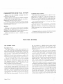
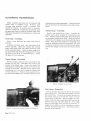
CARBURETTER TUNING
The method of tuning carburetters is identical with
that given for 3'8 litre "E" Type cars, however, the
idting speed on standard transmission cars should be
?00 r.p.m, in order to eliminate any chatter from the
constant mesh gears in the all-synchromesh gearbox.
On automatic transmission 212 cars, the idling
speed should be 500 r.P.m.
The fuel feed line fi.lter incorporates a renewable
frbre filter element. This element should not be
cleaned but must be renewed every 12,000 miles.
When renewing, the two sealing washers should also
be replaced.
If sediment build-up is excessive, the element should
be renewed more frequently than stated above.
1FFY.s.24.
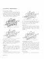
THE FUEL SYSTEM
THE PETROL PUMP
(O) is bounded by a fleiible plastic spring loaded
diaphragm (L) contained by the vented cover (P)'
Description (Fig. 2)
Sealing of the diaphragm (L) is provided by the rubber
sealing ring (L.2).
The magnetic unit consists of an iron coil housing,
an iron core (Q), an iron armature (Al) provided with
The pump consists of three main assemblies, the
main body casting (A); the diaphragm armature and
magnet assembly (M) contained within the housing;
and the contact breaker assembly housed within the
end cap (T2). A non-return valve assembly (C) is
affixed to the end cover moulding to assist in the
circulation ofair through the contact breakerchamber.
The main fuel inlet (B) provides access to an inlet
air bottle (I) while access to the main pumping
chamber (N) is provided by an inlet valve assembly.
This assembly consists of a Melinex valve disc (F)
permanently assembled within a pressed-steel cage'
held in position by a valve cover (E1)'
The outlet from the pumping chamber is provided
by an identical valve assembly which operates in the
reverse direction. Both inlet and outlet valve assemblies
together with the filters are held in position by a clamp
plate (H). The valve assemblies may be removed by
detaching the clamp plate (H) after removing the selftapping screws. A filter (E) is provided on the delivery
side of the inlet valve assembly. The delivery chamber
Page CY.s.2
a central spindle (P1) which is permanently united
with the diaphlagm assembly (L1)' a magnet coil (R)
and a contact breaker assembly consisting of parts
(P2), (U1), (U), (T1) and (V)' Between the coil
housing and the armature are located eleven spherically
eáged roliers (S). These rollers locate the armature
(41) centrally within the coil housing and peimit
freedom of movement in a longitudinal direction.
The contact breaker consists of a bakelite pedestal
moulding (T) carrying two rockers (U) and (U1) which
are both hinged to the moulding at one end by the
rocker spindle (Z). These rockers are interconnected at
their top ends by means of two small springs arranged
to give a throw-over action. A trunnion (P2) is carried
by the inner rocker and the armature spindle (Pl) is
screwed into this trunnion' The outer rocker (U) is
fitted with two tungsten points which contact with
corresponding tungsten points which form part of the
CARBURETTERS
AND FUEL
SYSTEM
L
L2
D
(J
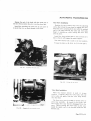
A
Fig,
2.
The
Petrol pump.
WARNING: If at any time, it
becomes necessary ro blow
through the fuel feed pipes the outlet pipes must be disconnected
from the pumps. Failure to observe this procedure will cause
the Melinex valves to be displaced or damaged.
Page CY.s.3
CARBURETTERS
(þ
AND FUEL
SYSTEM
connected \'/ith one ehd of the coil.
The other end of the coil is connected to a terminal
As the armature nears the end of its stroke the throwover mechanism again operates, the tungsten points
(W) while a short length of flexible wire (X) connecting
remake contact and the cycle of operations is repeated.
the outer rocker to one of the screws holding the
pedestal moulding onto the coil housing provides an
earth return to the body of the pump. It is important
that the body of the pump be effectively earthed to
the body of the vehicle by means of the earthing
The spring blade (V) rests against the small projection moulding (T) and it should be set so that, when
the points are in contact, it is deflected away from the
spring blade
terminal provided on the flange of the coil housing.
moulding. The gap at the points should be approximately '030' (75 mm.) when the rocker (U) is
manually deflected until it contacts the end face of the
coil housing.
OPERATION
'When
the pump is at rest the outer rocker (U) lies
in the outer position and the tungsten poìnts are in
contact. Current passes from Lucar connector (W)
through the coil and back to the blade (V), through
the points and to earth, thus energising the coil and
attracting the armature
(Al).
The armature, together
urith the diaphragm assembly, then retracts thereby
sucking petrol through the inlet valve into the pumping
(N). When the armature has travelled
chamber
nearly to the end of its stroke, the throw-over
mechanism operates and the outer rocker moves
rapidly backwards, thus separating the points and
breaking the circuit.
, The spring (Sl) then reasserts itself forcing the
armature and diaphragm away from the coil housing.
This action forces petrol through the delivery valve
at a Íate determined by the requirements of the engine.
Page CY.s.4
REMOVAL
Remove both inlet and outlet pipes from the side of
the pump by withdrawing the banjo bolt and washers.
Disconnect the electrical feed cable to the pump by
unscrewing the knurled knob on the end of the pump.
Remove the two self-locking nuts attaching the pump
to the bracket and withdraw the two washers from
each stud. The pump can now be withdrawn from the
bracket leaving the two rubber grommets in position.
The rubber grommets in the brackets should be
examined for deterioration and replaced if necessary,
otherwise excessive petrol pump noise may result.
REFITTING
Refitting is the reverse of the removal procedure.
AND FUEL
CARBURETTERS
SYSTEM
t\ ll
tut
t8 l9
lrl,l
F
Ëe
,u
i,
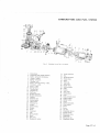
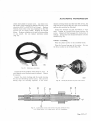
Fig.
3.
Exploded view of
l. Pump body.
2. Diaphragm and spindle assembly.
3. Roller-armature centralising.
4. Washer-impact.
5. Spr.ing-armature.
6. Housing-coil.
7. Sc¡ew-securing housing-2 B.A.
8, Connector-e a¡th.
9. Screw- -4 B.A.
10. Spring washer.
I l. Terminal tag.
12. Terminal tag.
13.' Earth
tag.
14. Rocker pivot pín.
15. Rocke¡ mechanism.
16. Pedestal.
17. Terminal stud.
18. Spring washer.
19. Lead washe¡.
20. Terminal nut.
21. Washer.
22. Contact blade.
23. Washer.
24. Screw.
25. Condenser.
26. CIip.
27. Spring washer.
28. Screw.
29. End cover.
30. Shakeprocf washer.
the;:ttol
I
28
pump.
31. Lucas connecto¡.
32. Nut.
33. Insulating sleeve.
34. Clamp plate.
35. Screw.
36. Valve cap.
37. Inlet valve.
38. Outlet valve.
39. Sealing washer.
40. Filter.
41. Gasket.
42. Vent valve.
43. Sealing band.
44. Joint.
45. Inlet ai¡ bottle cover.
46. Dished washer.
47. Spring washer.
48. Screw.
49. Outlet connection.
50. Fibre washer.
51. Cover.
52. Screw.
53. 'O' ring.
54. Diaphragm barrier.
55. Sealing washer.
56. Diaphragm plate.
57. Diaphragm.
58. Spring end cap.
59. Diaphragm spring.
Page CY.s.5
CARBURETTERS
AND FUEL
SYSTEM
of the delivery flow-smoothing
device should only be undertaken if the
operation of it is faulty, and if the necessary
equipment for pressure-testing after assembly
is available. On this understanding proceed
Note: Dismantling
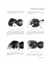
DISMANTLING (Fie.3).
Contact Breaker
Remove the insulated sleeve (33), terminal nut (32),
and connector (31), together with its shakeproof
washer (30). Remove the tape seal (if fitted) and
take off the end-cover.
Unscrew the 5 B.A. screw (24) which holds the
contact blade (22) to the pedestal (16) and remove the
condenser (25) from its c1ip. This will allow the
washer (23), terminal tag (1 1), and the contact blade
to be removed.
as follows:
Remove the four 4 B.A. screws (52) securing the
delivery flow-smoothing device vented cover (51),
remove the cover, the diaphragm spring (59), rubber
'O' ring (53), spring cap (58), diaphragm (57), barrier
(54), diaphragm plate (56) and sealing washer (55).
Remove the single 2 B.A. screw (48), securing the
inlet air bottle cover (45). Remove the cover and
gasket (44).
Unscrew the inlet and outlet connections.
Coil housing and diaphragm
Unscrew the coil housing securing screws (7), using
thick-bladed screwdriver
to avoid damaging
a
the
screw heads.
Remove the earthing screw (9).
The coil housing (6) may now be removed from the
body (1). Next remove the diaphragm and spindle
assembly (2) bV taking hold of the diaphragm and
unicrewing it anti-clockwise until the armature spring
(5) pushes the diaphragm away from the coil housing.
It is advisable to hold the housing over the bench so
that the 1 I brass rollers (3) will not fall on the ff.oor.
The diaphragm and its spindle are serviced as a unit
and should not be separated.
INSPECTION
If gum formation has occurred in the fuel used in
the pump, the parts in contact with the fuel will have
become coated with a substance similar to varnish'
This has a strong stale smell and may attack the
neoprene diaphragm. Brass and steel parts so affected
can be cleaned by being boiled in a 20 per cent'
solution of caustic soda, dipped in a strong nitric acid
solution and finally washed in boiling water. Light
alloy parts must be well soaked in methylated spirits
and then cleaned.
Pedestal and rocker
Remove the end-cover seal washer (21), unscrew the
terminal nut (20), and remove the lead washer (19).
This will have flattened on the terminal tag and thread
and is best cut away with cutting pliers or a knife.
Uhscrew the two 2 B.A. screws (28), holding the
pedestal to the coil holrsing, remove the earth terminal
tag (13) together with the condenser clip (26). Tip
the pedestal and withdraw the terminal stud
(17)
from the terminal tag (12). The pedestal (16) may now
be ¡emoved with the rocker mechanism (15) attached.
Pr-rsh
out the hardened steel pin (14) which holds the
rocker lnechanism to the pedestal and separate the
4.
Tlte terntinal offattgettrcnl.
two.
Fig.
Body and valves
A-Doublc coil
Unscrew the two Phillips screws (35) securing the
valve clamp plate (34), remove the valve caps (36),
valves (37) and (38), sealing washers (39) and fìlter (40).
Page CY.s,6
B-Cable
spt ing waslrcr.
tag.
C Leatl ¡'ather.
l)-C¡unl(t sunk nut.
CARBURETTERS
AND FUEL
SYSTEM
Clean the pump and inspect for cracks, damaged
joint faces and threads.
Examine the plastic valve assemblies for kinks or
damage to the valve plates. They can best be checked
by blowing and sucking with the mouth.
Check that the narrow tongue on the valve cage,
which is bent over to retain the valve and to prevent it
being forced out ofposition, has not been distorted but
allows a valve lift of approximately S in. (1.6 mm.).
Examine the delivery flow-smoothing device diaphragm, barrier, plate, sprìng, and spring cap for
damage. if in doubt, renew the diaphragm.
Examine the inlet air bottle cover for damage.
Examine the valve recesses in the body for damage and
if it is impossible to remove the corrosion,
or if the recess is pitted, the body must be discarded.
corrosion;
Clean the filter
fractures, renew
if
with a
brr-rsh and examine for
Fig.
necessary.
5.
Attaching the pedestal to the coil housing.
Examine the coil lead tag for security and the lead
insulation for damage.
Examine the contact breaker points for signs of
burning and pitting; if this is evident, the rocker
assembly and spring blade must be renewed.
obtain the correct "throw over" action; it is also
essential that the ¡ockers are perfectly free to swing on
the pivot pin and that the arms are ñot binding on the
Iegs of the pedestal.
Examine the pedestal for cracks or other damage, in
to the narrow ridge on the edge of.the
rectangular hole on which the contact blade rests.
Examine the non-return vent valve in the end-cover
for damage, ensure that the small ball valve is free to
Assemble the square-headed 2 B.A. terminal stud to
the pedestal, the back of which is recessed to take the
move.
square head.
particular
Examine the diaphragm for signs of deterioration.
Renew the following parts:
all fibre and cork
'O' section sealing rings, rollers
showing signs of wear oll periphery, damaged bolts,
washers, gaskets, and
and unions.
If
necessary the rockers can be squared up
with
a
pair of thin-nosed pliers.
Assemble the 2 B.A. spring washer (l) (Fig. 5), and
put the terminal stud through.the 2 B.A. terminal tag
(2), then fit the lead washer (3) and the coned nut (4)
with its coned face to the lead washer. (This makes
better contact than an ordinary flat washer and nut).
Tighten the 2 B.A. nut and finally add the endASSEMBLY
Pedestal and rocker
Note: The steel pin which secures the rocker mechanism to the pedestaÌ is specially hardened and
must not be replaced by other than a genuine
S.
U. part.
Jnvert the pedestal and fit the rocker assernbly to it
by pushing the steel pin (14, Fig. 3) through the small
holes in the rockers and pedestal struts. Then position
the centre toggle so that, rvith the inner rocker
spindle in tension against the re¿rr olthe contact point,
the centre to-egle spring is above the spindle on which
the rvhite rollers run. This positioning is important to
cover seal washer (5).
Assemble the pedestal to the coil housing by
fitting the two 2 B.A. pedestal screws (6), ensuring
that the spring washer (7) on the left-hand screw
(9 o'clock position) is between the pedestal and the
earthing tag
(8).
When a condenser is fitted, its wire
clip base is placed under the earthing tag and
the
spring washer is not required.
Tighten the screws, taking care to prevent the
earthing tag (8) from turning, as this will strain or
break the earthing ff.ex. Do not tighten the scrervs or
the pedestal will crack.
Do not fit the contact blade at this stage.
Page CY.s.7
CARBURETTERS
AND F[.'EL
SYSTEM
Diaphragm assembly
Place the armature spring into the coil housing with
its larger diameter towards the coil (5, Fig. 3).
Before fitting the diaphragm make sure that the
impact washer is ûtted to the armature. (This is a
small neoprene washer that fits in the armature recess).
Do not use jointing compound or dope on the dia-
phragm.
Fit the diaphragm by inserting the spindle in the
hole in the coil and screwing it into the threaded
trunnion in the centre of the rocker assembly.
Screw in the diaphragm until the rocker will not
"th¡ow over" ; this must not be confused with jamming
the armature on the coil housing internal steps.
Fit the I 1 brass centralizing rollers (3, Fig. 3) by
turning back the diaphragm edge and dropping the
rollers into the coil recess. The pump should be held
in the left hand, rocker end downwards, to prevent
the rollers from falling out.
Fit the contact blade and adjust the finger settings as
in "Contact gap setting", then carefully
described
remoYe the contact blade.
This is done to prevent the roliers from falling oui
when the coil housing is placeci on the bench prior
to fitting the body, and is not intended to stretch the
diaphragm before tightening the body screws.
Body components
The valve assemblies are retained internaliy in the
body by a clamp plate secured with self-tapping
screws (35, Fig. 3). The ìnlet valve recess ín the body
is deeper than the outlet recess to aliow for the filter
and extra washer. Another feature of these pumps is
the incorporation of an air bottle on the inlet and a
flow-smoothing device on the deiivery side.
The inlet air bottle is a chamber in the body casting
blanked off by a simple cover anci joint washer held
by a single screw. The delivery flow-smoothing
device is formed by a perforated metal plate which
is in contact with a plastic barrier backed by a rubber
diaphragm, all heid in position by a spring and endcap retained by a vented cover. This assembly seals
the delivery chamber in the body.
Screw in the inlet and outlet connections with their
sealing rings. Assemble the outlet valve components
into the outless recess in the following order, first a
joint washer, then the valve, tongLte side downwards,
then the valve cap.
Assemble the inlet valve into the inlet recess as
follou,s: first a joint washer, then the filter, dome
side downwards, then another joint washer, followed
by the valve assernbly, tongue side upwards, then the
valve cap,
Take care that both valve assemblies nest down into
their respective recesses, place the clamp plate on
top, and tighten down firmly to the body with the two
SCTCWS.
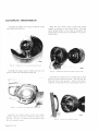
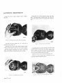
Fig.
6.
Setting the diaphragnt.
Holding the coil housing assembly in the left hand
in an approximately horizontal position (see Fig. 6),
push the diaphragm spindle in with the thumb of the
right hand, pushing firmly but steadily. Unscrew the
diaphragm, pressing and releasing with the thumb of
the right hand until the rocker just "throws over".
Now turn the diaphragm back (unscrew) to the nearest
hole and again 4 holes (two-thirds of a complete
turn). The diaphragm is now correctly set.
Press the centre of the armature and fit the retaining fork at the back of the rocker assembly.
Page CY.s.8
Replace the inlet air bottle cover with its joint
washer and tighten down the central screlv.
Place the sealing washer in the bottom of the
delivery flow-smoothing device recess, follow this with
the perforated diaphragm plate, dome side downwards,
then the plastic barrier, followed by the rubber diaphragm. Insert the "O" section sealing ring into the
recess and ensure that it seats evenly. Place the
diaphragm spring, large end tcwards the vented cover,
into the cover, place the spring end-cap on the small
end of the spring, pass the assembly tool through the
cover, spring, and end cap and turn it through 90"
so that tension may be applied to the spring during
assembly. Finally fit the spring and cap assembly onto
the diaphragm, tighten the four retaining screws, and
CARBURETTERS
release
AND FUEL
-l
l-
the assembly tool. The pump should be
pressure-tested after disturbance of the flow_smoothing
device.
Body attachment
Fit the joint washer to the body, aligning the screw
/:'
holes.
l,:
-;t
SYSTEM
'o7 0" (r . zs
t
xx)
'oos '(.t zsnx)
llltrt
.)' s
Offer up the coil housing to the body, ensuring
correct seating between them.
Line up the six securing screw holes, making sure
that the cast lugs on the coil housing are at the bottom,
'/
/t
insert the six 2 B.A. screws finger-tight. Fit the earth_
1'l:
retain their position; a displaced roller will cut the
diaphragm. It is not necessary to stretch the diaphragm
belore tightening the securing screws.
I,
ing screw with its Lucar connector.
Remove the roller retaining fork before tightening the
body securing screws, making sure that the rolìers
Tighten the securing screws in sequence as they
appear diametrically opposite each other.
f3õE3l
Contact blade (Fig. 7)
Fit the contact blade and coil lead to the pedestal
with the 5 B.A. washer and screw. The condenser
Fig.
7.
Rocker and tontact t lcarances,.
should be fitted with the tag placed under the coil lead
tag.
blade so that the points are
a
;:,*: fff :'"îi::"?: :'* ;iì:
overs the other. As the contact
blade is provided with a slot fo¡ the attachment screw,
some degree of adjustment is possible.
Tighten the contact blade attachment screw when
the correct setting is obtained.
Page CY.s.9
CARBURETTERS
AND FUEL SYSTEM
Check the gap betrveen rocker finger and coil
Contact gap setting
housin,e rvith a feeler gauge, bending the stop finger.
il necessary, to obtain a gap ol 070-:005 in.
(1.8-l_.13 mnr.).
Check that when the outer rocker is pressed onto the
coil housing, the contact blade rests on the narrow
rib or ridge rvhich projects slightly above the main
face of the pedestal. If it does not, slacken the
contact blade attachment screw, slving the blade
clear of the pedestal, and bend it downwards a
sufficient amount so that rvhen repositioned it rests
against the rib lightly, over-tensioning of the blade
rvill restrict the travel of the rocker mechanism'
Correct positioning gives a gap of '035" +'005'
('9+'13 mm.) between the pedestal and tip of spring
bìade (Fig. 7).
End-cover
TLrck all spare cable into position so that ìt cannot
foul the rocker mechanism. Ensure that the end-
cover seal rvasher is in position on the terminal stud,
fit the
bakelite end-cover and lock washer, secure
with the brass nut, fit the terminal tag or connector,
and the insulated sleeve.
The pump js now readY for test.
After test, replace the rubber sealing balld over the
end cover gap and seal with adhesive tape.
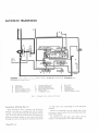
Fig. 8. Tht lt¡tt¡tirttt rtf'lltc ltt'ltrtl ptrttt¡t.
( l-'i.rttl
lttal
cotr¡tt'l,.
/ll.r¿I r/totr'r lt¡Ltttìtttt ilt t,pL'tt
Page CY.s.l0
2-\üll(t
ttt¡ulel
SECTION D
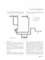
COOLING SYSTEM
'E' Type
series 2 have a sealed cooling system with
a vertical flow radiator and an expansion tank.
The thermostat is retained in a revised housing.
The radiator top tank incorporates a plain (nonpressure) cap, the pressure cap being fitted to the
expansion tank mounted on the bulkhead.
PRESSURE CAP RATING
WithStandardEquiprnent ..
7lb.
With Air-Conditioning Sysrem
l3 lb.
Instructions for filling or checking the coolant level
in the system differ lrom those stated for earlier cars
fitted with the cross flow radiator. as follows:-
Filling Up
Remove the radiator and expansion tank filler caps.
Fill the radiatol to the bottom ol
the filler neck.
Replace the filler cap and tighten down lully.
Top up the expansion tank to the hall-way ntark,
refit the cap and tighten down lully.
Checking the Coolant Level
IMPORTANT: The coolant level must be checked at
the expansion tank and NOT at the
radiator top tank.
Cl'reck when the systent is COLD.
Renrove the pressure cap and top up to the halfl-way
mark in the tank.
Replace the pressure cap and tighten down fully.
Refilling the Cooling SystemImportant
When refilling the cooling system following
complete drainage, place the heater tempera-
ture control in the "Hot" position to allow
the heater circuit to be filled with coolant.
Re-check the level alter running the engine
lor a short period.
THE RADIATOR
Removal
Release the filler cap, open the drain tap and drain
the cooling system. Conserve the coolant
il
anti-
freeze is ìn use.
Discolrnect the multi-pin socket lronr the lelt-hand
side ol the bonnet.
Renrove tr¡,o bolts. sell-locking lruts and rvashers
securing the bonnet linkage to the sub-frame.
Withdraw two hexagon-headed pivot pins and
to the sub-frame
front low'er cross tube, and remove ihe bonnet
washers securin_e the bonnet pivot
assembly.
Release the l-rose clips and disconnect the
bottont hoses lrom the radiator.
Fig. l, The expansiott tank atd pressure cap.
(lnset shows Íhe pressure cap frted to cars *'ith
À i r-Cottdi
t
ioni ttg Equiptnett t ¡.
Note: Care must be taken to ensure that the radiator
and the expansion tank filler caps are not
reversed.
top and
Disconlrect the oil cooler pipes (2 + Z automatic
transmission cars only) and blank off the unions to
prevent loss of oil.
Remove si.t setscrews securing the cor.vl to the
matrix side brackets. Disconnect the fan thermostat
switch cables at the cable.junction.
Release the radiator- duct panel from the bottom
ol the nlatrix b1, r'emovin_e t\^,o setscrews.
Remove the t\\,o bottom fixing nuts and rubber
mounting
u ashers.
Page DY.s.1
COOLING SYSTEM
Lilt oLrt tllc |adiutor l1]atrix alld collect the rubber
viashcrs fìtted bct*ccn thc bottolr tank and the
nrountirrg brackcts.
NOTE : Il air-conditioning equiptriertt is fitted to the
car, the condelrscr unit sliould be lelt irl
position after renroval ol the two setscrcws
seculing thc sicle support brackets to the
tì1at
r¡x.
DO NOT DISTURB THE HOSE
CON-
NECTIONS AT TFIE CONDENSER UNIT.
IT IS DANGEROUS FOR AN Ur.'QLTALIFIED PERSON TO ATTEMPT TO DISCONNECT OR REI\IOVE ANY PART OF
THE AIR-CONDITIONING SYSTEI\,{.
Care nr ust be takcn rvhcn reltloving
Refitting
Refitting is the l'everse
ol
the l'enroraì llrocccl Lt t'c
Rcncrv all
To aroid distortion ol tìre flangc laces clo lrot
gaskets.
ovcr-tighterr tlte
ntLts
RADIATOR COWL
Removal
Discolltrect the cablcs lronl the
Renrove six setscreu's securitlg
rad
triitl fall lllotors'
tlle col'l to the
iator aud l'enrove the cou'l colnplctc rvith
falr
motors alrd nrottnting brackets.
Refitting
Relìtting is tlre l'everse ol the removal proccdure'
tlre
radiator matrix that the fins ol the condelrscr
are not danraged.
FAN I\,{OTORS
move the fan cowi as detailed above.
Renrove three nuts and setsct'ervs sccuritrg cach lall
mounting bracket to the corvl and clctach the brackct
Re
Refitting
Refitting is the reverse of the renroval procedure.
bly.
Renrove lour uuts and washers sccltring cach nlotot
and detach the motor units lrom thc brackets.
assenr
TT{ERMOSTAT
The thermostat differs lronl that stated on
D. 8. in
lespect
ol
Page
the nrounting only.
Renloval
Drain sr.rfficient coolant from the systenl to allow
to lalI below the thermostat.
Disconncct tllc thrcc hoscs [l'ottt tllc thcrlttortltt
the level
hoLrsing.
Rcnrore thlce nuts and rvashcrs arld dctaclt tltc
housirrg to gairr access to the therlrtostlrt.
Page DY.s.2
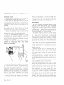
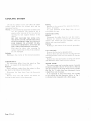
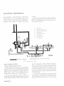
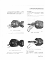
WATER PUMP
The water pump and mounting remain basically
the same as detailed in the 3.8 'E'Type Service Manual
with the exception of the pump body and the impeller
(See Fig. No. 3) which have been redesigned to give
a higher flow rate of coolant.
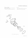
It is important to note when fitting the impeller
to the spindle that the dimension shown in Fig. 2
is obtained when measured with a feeler gauge.
COOLII.TG SYSTEM
3
5
I
o
U
I
I
@
7
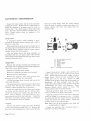
s4.
Fig.
3.
E.rplotled yicx, uf the woter pnnp.
Fãao¡l
'Ol5
(e ar
!'9¡3
r
oz uu)
I . I mpeller.
2. Seal.
3. Th rower.
4. Spindle and bearing assembly.
5. Gasket.
6. Pump body.
7. Allen-headedlockscrew.
8. Locknut.
9. Pulley carrier.
0. Pu l ley.
I L Spring washer.
12. Setscrew.
13. Drive belt.
14. Adaptor for heater return pipe.
15. Copper washer.
1
4050A
Fig.
2.
Sectioned view of *'ater puntp.
Page D y-s-3
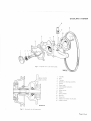
SECTION E
CLUTCH
CL UTC H
THE CLUTCH UNIT
Ð
Iì
4
60
ll
li
I
,tl
I
t2
wzl
6. Fulclum ling
7 Diaphragm spring
8. Cover pressing.
9. Release plate.
10. Retainer.
I. Dliverr plate.
2 Prcssure plate
I R-ivet.
4. Centre sleeve
-5. Belleville washer.
Fig.
l.
l. Tab washer.
Il. Setscl'ew.
ll. Retainer.
14. Rclcase bearing
I
Exploded view o.[ tltc rliuphta¿¡nt spritq cluttlt.
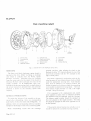
SERVICING
coincide, and that, when refitting the clutch
The Borg irnd Beck d iaphragnr spring clutch is
serviced in the U.K. ONLY by fitting an exchange
unit which is available fronl the Works, Spares
Division. Coventry. IndividL¡al parts ¿lre available
lrom the sanre source for the repair ol this clutch in
Overseus Mlrkets u'here exchan-se units may not be
reudily u\rilrble. lT IS ESSENTIAL when over-
dou,el holes coincides with the
haLrlirrg the diaphra-arrt sprirtg clLrtch. to ri-eidly observe
the service instrLtctions detailed belorv and particular
attcntion is dntivtr
req
u
i
to the necessar)'special
tools
red
GENERAI- INSTRUCTIONS
To enlble the balance of the rtsserrrbly to be preserved ¿rlter disnrlntlin-g. there are corresponding
pilint m¿rrks on the cover plate and driving plate. In
addition. there are corresponding reference numbers
stamped in the flanges of the cover and drivin-e plate.
When reassembling ensure that the markings
Page EY.s.2
flywheel, the letter
edge
"8"
stan.rped adjacent
"8"
to
the
to one ol the
stamped on the
ofthe flywhecl.
Thc clutch is balanced in conjunction with the fìywheel by means of loose balance pieces rvhich are fitted
Lrnder the appropriate secLrling bolt. Each balance
piece must be refitted in its original position. the
nunlber starnped on the belance u,eight corlesponding
to the nLrmber stamped on the covor plate. There are
thlee balance iveights stam¡red l. 2 and 3. the rreight
stirmped 3 being the heaviest.
If it is necessary to fit a replacement unit, clutch
units supplied as spares have no reference numbers
anci therefore must be balanced with the flywheel.
The balance weight number should be stamped on
the cover adjacent to the weight position. The letter
'B' should be stamped on the cover opposite the 'B'
on the flywheel.
ll the graphite release bearing ring is badly rvorn it
should be replaced by a complete bearin-e assentbìy.
cLUTCI-{
CLUTCH REMOVAL
In order to remove the clutch, the engine and gearbox must first be removed (see page B.y.s.4).
Remove gearbox and clutch housing from engine.
Remove the bolts securing the clutch to the flywheel
and withdraw the clutch assembly.
Retain any balance weight fitted.
DISMANTLING
Removing Release Plate
The centrally moLrnted release plate is held in
position by a small centle sleeve which passes through
the diaphragm spring and belleville washer into the
release plate.
To lree the plate, collapse the centre sleeve with a
hammer and chisel. To avoid any possible damage
whilst carrying or.tt this operation, support the release
plate in the locating boss of the special tool which
should be held firmly in a vice.
Separating the Pressure Plate from Cover pressing
Knock back the locking tabs and remove the three
setscrews securing the pressure plate to the straps
Fig.
3.
Coltapsing
,,n ,:l!{:,.',rrre with
a hantncr anct
riveted to the cover pressing. These straps within the
cover pressing must NOT be detached as this is an
assembly reduced to ìts minimum as a spare part,
Dismantling the Cover Assembly
Remove the rivets securing the diaphragm spring
and fulcrum rings by machining the shank of the rivets
using a spot face cutter.
IT IS ESSENTIAL that the thickness of the cover
is not reduced in excess of .005' (. 127 mm.) at any
point. The remaining portions of the rivets may be
removed with a standard pin punch.
THIS DIMENSION HUSI NOT
-,Lt"*5
COVER
ULCRUIl RINGS
D APHRi{G¡1
5PRING
RIVET
Fig.
¿L
|1771
Do nor reduce the thickness of tlrc coter pres.sing
itt c-rcess of .005" (. 127 ntn.\.
REBUILDING
The Cover Assembly
Fig.
2.
Clutclt and
f .t,t'lteel balant.ìn.g
Prior to rebuilding, check the cover pressing for
distortion. Bolt the cover firmly to a ffat surface
plate and check that measurements taken at various
points lrom the cover flange to the machined land
inside the cover pressing do not vary by rnore than
'007" (.2 mm.). If the measuremenr exceeds this
figure the cover must be replaced.
Page E.Y.s.3
CL UTC H
To achieve a satisfactory result when riveting the
diaphragm spring into the cover pressing, a special
tool must be fabricated to the specifications given in
Fig. 6.
All parts except the spring can be made from mild
COVER PRESSING
SURFACE PLATE
Fig.
5. ' The nu'a:;urenrcnt "A"
B
Flat rvasher
Nut.
F
C
Setsc rerv
G
D
S
pring
H
A
tttu.rt
'007" ('2 mnt.).
E
Washer
Tube.
Washer.
Bolt.
nol rort b.t'ntore thatt
steel. Position the fulcrum ring inside the cover
pressing so that the location notches in the ftrlcrum
ring engage a depression betlveen tlvo of the larger
diameter holes in the cover pressing.
Place the diaphragm spring on the fulcrum ring
inside the cover and line the long slots in the spring
with the small holes in the cover pressin-e. Locate a
further fulcrum ring on the diaphragm spring so that
the Ìocation notches are diametrically opposite the
location notches in the first ring. Fit new shouldered
rivets, ensuring that the shouldered portion of each
seats on the machined land inside the cover.
s''BAR
SIZE
Fig.
-
6.
Dimcnsion rtf special tool Jòr cotnpressìng llte
diaplragnt spring x'hcn rit'eting the .spring to
LOter Ptessulg.
Page E.Y.s.4
CLUTCH
M33
Fig.
7.
Assenbly of cover pressing and.[ulcrunt ring.
Place the base of the special tool on to the rivet
heads. Invert the clutch and base plate.
Fit the collar to the large bolt and fit the large bolt
complete with spring, spider and collar into the tapped
hole in the base. Position the three setscrews on the
spider so that they contact the cover pressing. Tighten
down the centre bolt until the diaphragm spring
becomes flat and the cover pressing is held firmly by
the setscrews.
Rivet securely with a hand
Fig.
8.
punch.
Cltttch antl bose plate inyerred.
Fig.
9,
Tighten down the large nut so !hat thc cliaphragtn
spring is conrpressed flat.
:
FrSf.
l0
Riveting v'ith a hand prrnch,
Page E.Y.s.5
CLUTCH
Ässembling the Pressure Plaie to Cover Fressing
Before lsser.nbling ïhe ¡tressltre plate to the covel'
iuessins. examine the piate ibl'lrrly signs ol r+'ear.
'r.hoirld it have been darrageci or have excessive
Position the pressure plate inside the covel'assernbly
so that the lugs on the pìate engage the slots in the
cover pressing. fnsert the three setscrews throtrgh
the straps rvhich are riveted to the cover pressing and
Iock with the tab washet's.
:cor-rne, it is stron-eiy recommencied that a new plate is
íìtted. lf. horvever, renewal ol the pressure plate is not
cossible, glinding of the original unit may be under-
iaken by a conlpetent rnachinist, bearing in milrd that
incorrect grinding oithe plate may seriously affect the
operation oi lhe ciutch. IN NO CIRCUMSTANCES
MUST THE P!ì.ESSURE PLATE tsE GROUND TO
ATHICKNESS CF
:-ESS
THAN
1,010' (21.178 mm.)
Fitting a New Release Plate
A
speciat
tool (Part No. SSC.805) is
available
lrom ALrtomotive Products Ltd., Service and Spares
Division, Banbury, England, for completion of this
operation. Ensrtre that all parts of the clutch and
special tool are clean.
Grip the base ol the tool jn a vice and place the
locating boss into the cotlnterbore ol the base plate.
Place the release plate. face downwards, into the
counterbore of the locating boss.
Appìy a Iittle high rnelting point grease to the tips
diaphragm spring fingers and position the
plate friction face upwards, on to the
pressure
clr,rtch,
release plate.
of the
Staking guidc
4
W rrshc r.
_i
Locirting hasc
Fig. I l.
Page E.Y.s.6
Spet
ial Trntl
Busc plate.
Knullerl nut
Pu nch
(.çSCJü-s).
Fig 12,
Fittin.!: tltc vl¿ev' und ball¿tillc tttthet
'
CLUTCH
Fig.
t3.
Staking tlte sleeve to the release plate.
Place the belleville washer, concave surface towards
the spring, on to the centre of the diaphragm spring
and then push the centre sleeve through the spring
into the reiease plate.
Fie 14. Centralising the driven plate on the flywheel by
means of a duntnty plate.
Drop the special washer into the sleeve and insert
the staking guide into the centre of the assembly. Fit
the knurled nut to the thread on the staking guide,
tighten down until the whole assembly is solid. Using
the special punch, stake the centre sleeve in six places
into the groove in the release plate.
box.
Centralize the plate on the flywheel by means
of the dummy shaft (a constant pinion shaft may be
used for this pr-rrpose). Secure the cover assembly
rvith the six setscrews and spring washers, tightening
REFITTING
Place the driven plate on the flywheel, taking care
that the larger part of the splined hub faces the gear-
the screws a turn at a time by diagonal selection.
Ensure that the "8" stamped adjacent to one of the
dowel holes coincides with the "B" stamped on the
periphery of the flywheel.
Page E.Y.s.7
CLUTCH
CONDITION OF CLUTCH FACINGS
The possibility of further use of the friction facings
of the clutch is sometimes raised, because they have a
polished appearance after considerable service. It is
natural to assume that a rough surface will give higher
frictional value against slipping. but this not correct.
Since the introduction ol non-metallic facings of the
moulded asbestos type, in selvice a polished surface is
a common experience, but it must not be confused
with a glazed surface which is sometimes encountered
due to the conditions discussed below.
generated by slip which occurs under normal
starting conditions. The burning off of the small
amount of lubricant has the effect of gradually
darkening the facings, but provided the polish on
the facings remains such that the grain of the
material can be clearly distinguished,
little effect on ciutch performance.
(c) Should increased quantities of oil or grease obtain
access to the facing, one or two conditions, or a
combination of the two, may arise, depending
The ideal smooth or polished condition will provide
upon the nature of oil, etc.
a normal contact, but a glazed surface may be due to a
(i) The oil may burn off and leave on the surface
a carbon deposit which assumes a high
glaze and causes slip. This is a very definite,
though very thin deposit, and in general it
film or a condition introduced, which entirely alters
the frictional value of the facings. These two conditions might be simply illustrated by the comparison
between a polished wood and a varnished surface. In
hides the grain of the material.
the former the contact is still made by the original
material whereas, in the latter instance, a film of dried
(ii) The oil. may partially burn and leave a
resinous deposit on the facings, . rvhich
frequently produces a fierce clutch, and
may also cause a "spinning" clutch due to
tendency of the facings to adhere to the
varnish is interposed between the contact surfaces'
The following notes are issued with a view to giving
useful information on this subject:-
has been in use for some little
perfect
conditions (that is, with the
time under
working
on true and polished or
facings
clutch
ground surfaces of correct material, without the
presence of oi1, and with only that amount of slip
(a) After the clutch
.
'
which the clutch provides for under normal conditions) then the surface of the facings assumes
flywheel or pressure plate face.
(iii) There may be a combination of (i) and (ii)
conditions which is likely to produce a
judder during clutch engagement.
condition.
Still greater quantities of oil produces a black
soaked appearance to the facings, and the effect
may be slip, fierceness, or judder in engagement,
etc., according to the conditions. If the conditions under (c) or (d) are experienced, the
clutch driven plate should be replaced by one
Should oil in small quantities gain access to the
clutch in such a manner as to come into contact
with the facings, it will burn off due to the heat
fitted with new facings, the cause of the presence
of oil removed and the clutch and flywheel face
thoroughly cleaned.
'a high polish, through which the grain of
the
material can be clearly seen. This polished facing
is of mid-brown colottr and is then in a perfect
(b)
it has very
Page E.Y.s.8
(d)
CLUTCH
FAULT FINDING
SYMPTOM
Drag or Spin
CAUSE
REMEDY
(a) Oil or grease on the driven plate facings.
(b) Misalignment between the engine and
Fit new facings or replace plate.
Check over and correct the alignment.
splined clutch shaft.
(c) Air in clutch system.
"Bleed" system. Check all unions
and
plpes.
(d) Bad external leak between the clutch
Renew pipe and unions.
master cylinder and the slave cylinder.
(e) Warped or damaged pressure plate or
Renew defective part.
clutch cover.
(f)
Driven plate hub binding on splined
shaft.
Clean up splines and lubricate with
small quantity of high melting point
grease.
(g) Distorted driven plate due to the weight
of the gearbox being allowed to hang on
clutch plate during assembly.
Fit new driven plate assembly using a
jack to take overhanging weight of the
gearbox.
(h) Broken facings of driven plate.
(i) Dirt or foreign matter in the clutch.
Fit new facings, or replace plate.
Dismantle clutch from flywheel and
clean the
are free.
unit;
see
that all working parts
Caution: Never use petrol
for cleaning out clutch.
Fierceness or
Snatch
(a) Oit or grease on driven plate facings.
or
paraffin
Fit new facings'and ensure isolation of
clutch from possible ingress of oil or
grease.
(b) Misalignment.
(c) Worn out driven plate
Slip
Judder
Check over and correct alignment.
Fit new facings or replace plate.
facings.
(a) Oil or grease on dliven plate facings.
(b) Seized piston in clutch slave cylinder.
Fit new facings and eliminate cause.
(c) Master cylinder piston sticking.
Free off piston.
(a) Oil, grease or foreign matter on driven
Fit new facings or driven plate.
Renew parts as necessary.
plate lacings.
(b) Misalignment.
(c) Bent splined shaft or buckled driven
Check over and correct ali_snment.
plate.
Fit new shaft or driven plate
assembly.
Page E.Y.s.9
CLUTCH
FAULT FINDING
Tick or Knock
REMEDY
CAUSE
SYMPTOM
Rattle
(continued)
(a)
(b)
(c)
(d)
(e)
Damaged driven plate.
Excessive backlash in transmission.
Wear in transmission bearings.
I
Fit new parts
as necessary.
Bent or worn splined shaft.
Release bearing loose on throw out fork.
Hub splines worn due to misalignment.
Check and correct alignment then fit
new driven plate.
Fracture of
Driven Plate
(a) Misalignment distorts the plate and
causes it to break or tear round the hub
Check and correct alignment and fit new
driven plate.
or at segment necks.
(b) lf the gearbox during assembly be allowed
to hang with the shaft in the hub, the
Fit new driven plate
assembly and
ensure satisfactory re-assembly.
driven plate may be distorted, leading to
drag, metal fatigue and breakage.
Abnormal
Facing Wear
Page E.Y.s.l0
Usually produced by over-loading and by
excessive clutch slip when starting,
In the hands of the operator.
SECTION F
GEARBOX
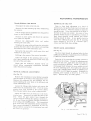
DESCRIPTION
The gearbox is of the four speed type with baulk-ring synchromesh on all forward gears. With the exception of
reverse, the detents for the gears are incorporated in the synchro assemblies, the three synchro balls engaging with
grooves in the operating sleeve. The detent lor reverse gear is a spring loaded ball which engages on a groove in
the
selector rod.
Two interlock batls and a pin located at the front of selector rods prevent the engagement of two gears at the
same time.
The gears are pressure fed at approximately 5 lb. per sq. in. (0'35 kg/cm.z) from a pump driven from the rear of the
mainshaft.
DATA
Identification number
Open 2 seater and F.H. Coupe
t J-t
KE 101 onwards
KJS 101 onwards
Ratios
I
2.933:1
1.905:l
Reverse
st gear
2nd gear
lst
3rd gear
1.389:1
4th gear
1.000:'l
3.378:1
gear-end float on mainshaft .005" to '007' ('13-'18 mm.)
to '008" (.13-.20 mm.)
3rd gear-end float on mainshaft '005" to '008" (.13-.20 mm.)
Countershaft gear unit end float .004" to .006" ('10-'15 mm.)
2nd gear-end float on mainshaft '005"
RECOMMENDED LUBRICANTS
Mobilube
GX
90
Spirax
90 E.P.
Esso Gear Oil
Gear Oil
cP 90it40
Multigear
SAE 90 E.P.
Lubricant EP90
Page
FY.s.i
GEARBOX
il
-rir-
(
I
I
ft(
)
l.í
Fig. l. Lon¡¡ittulinal v(tiott of tlttttl¡ ¿tnl ¡¡tatbot
Page FY.s.2
GEARBOX
GEAR,BOX ÐISMANTLING
REMOYAI- OF CLUTCH HOUSING
Important:
Detach the springs and remove the carbon thrust
Ensure that the rear washer (pegged to casing)
drops down in a clockwise direction looking from
the rear to avoid trapping the washer with the
reverse gear when driving the mainshaft forward
(see Fig. 2). This is effected by rocking the
bearing.
Unscrew the two nuts and remove the clutch slave
cylinder.
Remove the allen screw, push out the fulcrum pin
and detach the clutch fork.
Tap back the locking tabs and break the locking
wire and remove the eight setscrews.
Detach the clutch houbing.
gearbox casing and moving the reverse lever
backwards and forwards, or by pushing the
washer down with a piece of wire bent at right
angles.
REMOVAL OF TOP COVER
Place the gear lever in neutral.
Remove the eight setscreu,s and two nuts and
off the lid.
lift
R.EMOVAL OF REAR EXTENSION
Engage first and reverse gears to lock the unit.
Remove the split pin and unscrew the flange nut.
Withdraw the flange.
Remove the four setscrews and detach the rear
covef.
Remove the speedometer pinion and bush assembly
after unscrewing the retaining bolt.
Ð-
Withdraw the speedometer driving gear fronr the
mainshaft.
Remove the seven setscrews and withdrar¡, the
extension.
Collect the distance piece and oil pump driving pin.
REMOVAL OF OIL PUMP
From the inside face of the rear extension break
the staking and remove the three countersunk screws
securing the oil pump gear housing. Withdraw the
housing by entering two of the securing scrervs into
the tapped holes in the housing; sc¡ew in the two
screws evenly until the hor-rsing is free.
Mark the gears with marking ink so that they can
be replaced the same way up in the housing.
REMOVAL OF COUNTERSHAFT
Remove the fibre plug frorn the lront end
countershaft.
of
2.
Ensure that the rear,wash.er (intlicatal by arrov,) clrops
tlovtt itt a clockwise diraction.
REMOVAL OF CONST,ANT PINION SHAFT
Rotate the constant pinion shalt until the cutaway
portions of the driving gear are facing the top and
bottom of the casing otherwise the gear will foul the
countershaft.
With the aid of two levers ease the constant pinion
shaft and front bearing assembly forward until it can
be withdrawn (see Fig. 3).
DISMANTLING THE CONSTANT PINION
the
Drive out the counte¡shaft lrom the front of the
caslng.
Fig.
SHAFT
Remove the roller bearing from inside the constant
pinion shaft. On early cars, a spacer was also fitted
along with the needle roller bearing.
Page F.Y.s.3
GEARBOX
Tap back the tab washer and remove the large nut,
tab washer and oil thrower.
Tap the shaft sharply against a metal plate to dis-
Tap or press the mainshaft through the rear bearing
ensuring that the reverse gear is kept tight against the
first gear (see Fig. 5).
lodge the bearing.
REMOVAL OF MAINSHAFT
Rotate the mainshaft until one of the cutaway
portions in 3rd¡Top synchro hub is ìn line with the
countershaft (see Fig. a), otherwise the hub will
foul the constant gear or the countershaft.
Fig.
5.
Tapping the ntainshalt through the rear bearing.
Remove the rear bearing from the casing and fit a
hose clip to the mainshaft to prevent the reverse gear
from sliding off
Fig.
3.
þIt'ith the aid
of two levers
(see Fie. 6).
ease the conslant pinion shaft
forv'ard.
Fig.
6.
Removal of the mainshaft. Note the hose clip rttted to
lhe nninshaft lo relq¡n llte ret,erse gear.
Slacken the reverse iever bolt until the lever can be
moved to the rear.
Lift out the mainshaft forward and upward.
Lift out the countershalt gear unit and
Fie 4
Rotata the ttninshaft until one o.f the cuta*,ay portions
in SrdiTop s¡,nchro hub iç in line vitlÌ the ruunlershaft.
Page F Y.s.4
the needle bearings and retaining rings.
\Mithdraw the reverse idler shaft and
gear.
collect
lift out the
GEARBOX
DISNIANTLING THE MAINSHAFT
DISIVIANTLING THE SYNCHRO ASSE]\,IBT,\'
Note: The needle roller.s are
-craded on diameter and
rnust be kept in sets for their respective
Completely sur¡ound the synchro assentbly *ith a
cloth and pLrsh out the synchro hub fro¡n the operating
sleeve. ColÌect the synchro balls and sprines, and the
thrLrst melnbers, plungers and springs.
positions.
Remove the hose clip.
Withdraw the reverse gear frotr the mainshaft.
DISMANTLING TOP COYER
Withdraw the lst gear and collect the 120 needle
rollers, spacer and
sleeve.
Withdraw the 1st/2nd synchro assembly and collect
the two loose syncltro-rings.
Withdraw the 2nd speed gear and collect the 106
needle rollers leaving the spacer on the mainshaflt.
Tap back the tab washer and remove the large nut
retaining the 3rdlTop synchro assembly to the main_
shaft.
Withdraw the 3rd/Top synchro assembly from the
mainshaft and collect the two loose synchro-rings.
Withdraw the 3rd speed gear and collect
needle rollers and spacer.
Unscrew the self-locking nLrt and remove the
double coil spring, washer, flat rvasher and fibre
washer secLrring the gear lever to the top cover.
Withdraw the gear lever and collect the remaining
fibre washer.
Remove the locking wire and unscrew the selector
rod retaining screws.
Withdraw the 3rd/Top selector rods and collect the
selector, spacing tube and interlock ball. Note the
loose interlock pin at the front end of the lst/2ncl
selector rod.
Withdraw the reverse selector rod and collect the
reverse fork, stop spring and detent plr-rnger.
the
106
Withdraw the lst/2nd selector rod and collect the
fork and short spacer tube.
GEARBOX RE.ASSEMBLING
ASSEMBLING THE SYNCHRO ASSEMBLIES
The assembly procedure for the 1st,'2nd and 3rd, Top
synchro assemblies is the same.
Note: Although the 3rdiTop and lst/2nd synchro
hubs are similar in appearance they are not
identical and to distinguish them a groove is
machined on the edge of the 3rd/Top synchro
hub (see Fìg.7).
Assemble the synchro hub to the operating sleeve
with;
(i)
The wide boss of the hub on the opposite side to
the wide chamfer end of the sleeve (see Fig. g).
(ii) The three ball and springs in line with the teeth
having three detent grooves (see Fig. l0).
Fig.
7.
Identifcat iotr gt oove5-3rd/Top, synchro assentbl¡,.
Page FY.s.5
GEARBOX
Fit the three springs.
plr-rnqers and thrLtst mernbers
positions
correct
with glease: press down the
to their
thr¡,rst nrenrbers ¿rs tir ¿rs possible. Fit the three springs
¿rnd balls to tlre renr¿rining holes w'ith grease.
Fig.
8.
Assenbl,t,ol synchto hub.
Pack up the synchro hub so that holes for the ball
¿rnd springs are exactly level with the top of the
operating sleeve (see Fig.
Fig. l0
Fitting tlte s)'nchnt htú in tlte
sleev¿'
ll).
Compress the springs with ¿ large hose clip or a
piston ring clarÌp os shown in Fig. 12 and careftrlly
lilt off the synchro assernbly from the packin-q piece.
Depress the hLrb slightly and push down the thrr,lst
with a scre$'driver until they engage lhe
groove
in the operating sleeve (see Fig l3).
neutraì
members
@
Et88l
Fig.
9.
Sltowing llte tela¡ire posilions ol the detent ball,
Page FY.s,6
plttttget atrl lhnßt nt(ltb(t
Fig. 11. Fitting rlte springs, plungers an¿ tlttusl ttrcntb¿r.r
G EARB
Fig.
Fig.
12.
Contpressing lhe .rprings.
14.
OX
Tapping the hub into position.
CHECKING THE CLUSTER GEAR END FLO.{T
Finally tap the hub down until the balls can be
heard and felt to engage the neutral groove (see
Fig. 14).
Fit the reverse idler gear, lever and idler shaft.
Fit the pegged rear washer to its boss on the casing
with
grease.
Locate the outer thrust washer to the front of the
cluster gear with grease; lower the cluster gear into
position carefully. Insert a dummy shaft and check
the clearance between the rear thrust washer and the
cluster gear. The clearance should be .004,,-.006,
('10 mm.-15 mm.) and is adjusted by means of the
outer thrust washers. This is available in the following selective thicknesses
Part Number
c.1862/3
c.1862
c.1862/t
c.1862/2
c.1862/4
:-
Thickness
'152' (3.86 mm.)
'156" (3'96 mm.)
'159" (4.04 mm.)
'162'(4.11 mm.)
'164" (4'17 mm.)
Er?El
Fig. 13. Pushing down the Ihrust
mentbers.
.oo4:
ood(o-.rs"")_=:F
ASSEMBLING THE CLUSTER GEAR
Fit one retaining ring in the front end of the cluste¡
gear. Locate the 29 needle roller bearings with grease
and fit the inner thrust washer ensuring that the peg
on the rvasher locates in a groove machined on the
face of the cluster gear.
a
Fit a retaining ring, 29 needie roller bearings and
second letaining ring to the rear end of the
cluster gear.
Fig.
15.
Checking the clearance between the rear thrust washer
and the countershøft cluster gear.
Page FY.s.7
GEARBOX
ASSEMBLING THE CONSTÄNT PINION
SHAFT
Assembling is the reverse of the dismantling procedure but care must be taken to ensure that the
bearing is seated squarely on the constant pinion shaft.
ASSEMBLING THE MÄINSHÄ.FT
The re-assembly of the nainshaft is the reverse of
the dismantling instructions br.rt the following jnstructions should be noted.
(i) The end float of the gears on the mainshaft is
given in "Data" at the beginning of this section
and if found to be excessive the end float can
only be restored by the fitting of new parts.
(ii) The needle rollers which support the gears
on
the mainshaft are graded on diameter and rollers
of one grade only must be used for an individual
gear. The grades are identified by /1, /2, and
,''3 after the part number.
(iii) The "E" Type constant pinion,
countershaft and
3rd speed gear have a groove machined around
the periphery of the gear, see Fig. 16. This is to
distinguish the "E" Type gears from those fitted
to the same type of gearbox on other modeis
which have different ratios.
(iv) Fit a hose clip to prevent the reverse gear from
sliding off when assembling the mainshaft to the
caslng.
ÄSSEMBLING THE GEARS TO THE CASING
Withdrav,ç' the dummy shaft from the cluster gear
and, at the same time, substitute a thin rod keeping
both the dummy shaft and the rod in contact until the
dummy shaft is clear of the casing. The thin rod
allows the cluster gear to be lou'ered sufficiently in the
casing for insertion of the mainshaft.
Fit a new paper gasket to the front face of
the
caslng.
Enter the mainshaft through the top of the casing
and pass the rear of shaft through the bearing hole.
Enter the constant pinion shaft at the frolrt of the
casing with the cutaway portions of the tooth driving
member at the top and bottom.
Tap the constant pinion shaft into position and
into the spigot
enter the front end of the mainshaft
bearing of the constant pinion shaft.
Hold the constant pinion shaft in position and
a hollow drift tap the rear bearing into positiorr.
with
Withdraw the thin rod from the front bore of the
cluster gear approximately half wa¡, and lever the
cluster gear upwards, rotating the mainsl.raft and
constant pinion shaft gently until the cluster gear
meshes. Carefully insert the countershaft from the
rear and withdraw the rod. Fit the key locating the
countershaft in the casing.
REFITTING REAR EXTENSION
Refit the gears to the oil pump the same way as
removed, having previously coated the gears and
the inside of the pump body with oil. Secure the
pump housing with the three countersnnk screws and
retain by staking.
Fit a new paper
gasket
to the rear face of the
casing.
Fit the distance piece and driving
pump in the rear extension.
pin to the oil
Offer up the rear extension and secure with the
seven screws.
Fig.
16.
Sho*'ing thc groorc *,hich identifes lhe'E'
Page FY.s.8
t.t,pc geats.
Frt the speedometer driving gear to the mainshaft.
GEARBOX
Fit the speedometer driven gear and bush with the
hole in the bush in line with the hole in the casing
and secure with the retaining bolt.
Fit
a new gasket to the rear cover face.
Fit a new oil
seal
to the rear cover with the lip
facing forward.
Fit the rear cover to the extension noting that
the
setscrew holes are offset.
Fit the four bolts tq the companion flange, slide
on the flange and secure with flat washer with split
pln.
FITTING THE TOP COVER
Fit a new paper gasket.
Ensure that the gearbox and the top cover are in
the neutral position.
Ensure that the reverse idler gear is out of mesh
with the reverse gear on the mainshaft by pushing
the lever rearwards.
Engage the selector forks
with the grooves in the
synchro assemblies.
Secure the
top cover with the nuts and bolts noting
that they are of different lengths.
REFITTING THE CLUTCH HOUSING
Refitting the clutch housing is the reverse of the
removal procedure.
Fit a new oil seal to the clutch housing with the
lip of the seal facing the gearbox. The oil seal has a
metal flange and should be pressed in fully.
uìãd
Fig. 17.
Re-assentbled gearhox
prior to reJitting oJ'top
cover.
RE-ASSEMBLING THE TOP COVER
The two clutch housing securing bolts adjacent to
the clutch fork trunnions are secured with locking
wire; the remainder are secured with tab washers.
Note: After refitting the gearbox, run the car in top
gear as soon as possiblç to attain the necessary
mainshaft speed to prime the oil pump.
(see Fig. 20).
Re-assembly ol the top cover is the reverse of the
dismantling instructions. When assembling the selector
rods do not omit to fit the interlock balls and pin.
Renew the
"O" rings on the
To adjust the
selector rods.
reverse plunger
fit the plunger
and
spnng.
Fit the ball and spring and start the screw and
locknut; press the plunger inwards as far as possible
and tighten the screw to lock the plunger.
Slowly slacken the screr¡,until the plunger
is
released and the ball engages with the circular groove
in the plunger. Hold the screw and tighten the
locknut.
Fig.
I8.
The oil pump.
Page F,Y.s.9
GEARBOX
Fig 19. Plan ricv ol
gLttt lto-r
sltr¡r'in! ttl¿cl,¡r attan,{¿tttott
@
I
Fig.20
Page F Y.s, 10
l'ic¡ t¡l th¿ ttntlt'ttitlt t¡l tltt'tLtP ttttL't
SECTION FF
AUTOMAT¡C TRANSM ISSION
GENERAL DAT
lst Cear reduction
2nd Gear reduction
3rd Gear reduction
Reverse Gear reduction
AUTOMATIC SHIFT
I
tìe
SPEEDS
'2'88:l Final Drive
Throttle
Upsh ifis
Position
t- 2
Min
7-
2-
3
M.P.H.
DI
inr u nr
Futl
Kickdown
9
38-44
52-56
MinimLrnr
D2
-
t4
8-
8l
8
2373
37
20
-24
t4
23- 37
73- 8t
Full
Kickdown
Ze¡o
t2-20
60
K.P.H.
D
Minimum
ll-14
13-
23
Full
6I _11
37-
60
Kickdown
83-90
Minimum
D2
Full
K
ickdorvn
Zero
lr8-130
t3-
613
32-39
23
37- 60
il8- t30
96
l9 -32
Page
FFy.s..l
AUTOMATIC TRANS M ISSIO N
AUTOMATIC SHIFT SPEEDS
(continued;
l85x15 SP 4l HR Tyres-3.31:l Final Drive
Throttle
Position
Upshilts
t-
2
Downshifts
2-
3
3- 2
3-
|
2-l
M.P.H.
Minimum
DI
Full
Kickdown
ó-
8
33-40
45-49
Full
Kickdown
L
t3
6;2
70-
18
ll 5870-
Minimum
D2
il-
58
7 - 13
t9- 33
63-'tI
62
l9-
33
78
63-
7l
13
7
Zera
3l7-2t
l7
1
-2t
13
60
l0-
l8
5-
1t
K.P.H.
Minimum
DI
Full
Kickdown
9-
t3
s3-64
73-80
Minimum
Full
Kickdown
L
93 - t00
2l
t8
|3l
2I
-
t26
l0l -
18- 2t
93 - I00
|3 - 126
|3l-
ll3
-
Zero
t0l
53
I
14
28
values are permissible.
2E-34
2t
53
- il4
96
Note: Shilt points are approximate and not absolute values.
-34
Re¿rsonable devi¿rtions
16
lrom the above
-29
AUTOMATIC TRANSMISSION
TIGHTENING TORQUE FIGURES
tb. ft.
kgm.
Front pump to transmission
case bolts
17-
22
Front servo to transmission
case bolts
30-
35
Rear servo to transmission case bolts
n-
45
Centre support to transmission case bolts
20-
25
Upper valve bcdy to lower valve body bolts
48-
l0
Pressure regulator assembly to transmission case bolts
17-
22
Extension assembly to transmission case bolts
28r0-
t3
Case asselnbly-gauge hole plug
t0-
t5
Oil pan drain plug
25-
30
Rear band adjusting screw lock nut
35-
40
Front band adjusting screw lock nut
20-
2s
Detent lever attaching nut
35- N
Companion flange nut
m- tn
Bearing retainer to extension housing bolts
28-
Control valve body to transmission
Oil pan to transmission
case bolts
case bolts
Front pump cover attaching
screws
Rear pump cover attaching screws
],
(6.30 mm.)
6
33
lb. in.
hgm-
25-35
- 0-Æ
G58 - 0.69
0.24 - 0.35
058 - 0.69
D58 - &69
ù24 - ù35
ù24 - o'35
ù24 - t35
ùtr - Gl6
G08 - 0.17
50-60
Rear pump attaching screws Nos. lG-24
20-30
Governor inspection cover attaching screws
50-60
Covernor valve body to counterweight screws
50-60
Governor valve body cover screws
20-30
Pressure regulat<-rr cover attaching screws
20-30
Control valve body
20-30
screws
Control valve body plug
Control valve lower body plug
- 3.04
4.t5 - 4.70
5'53 - 6.22
2'76 - 3-46
o-55 - 0.83
1.il - 1.38
2.35 - 3.04
3'87 - 4-s6
r.38 - t'80
1.38 - 2.07
3.M - 4-1s
4-70 - 5.53
2.76 - 3-46
4.to - 5-53
12.4 - 16.58
3.87 - 4.56
2.35
i0-14
7-15
o.29
Page FF Y.s.3
AUTOMATIC TRANSMISSION
SPEelAt
SF:RVICE TOOLS
Service tools are not available from [lorg-\À'arlrlr
Linlited. Distributors and Dealers shoLrlcì obtairl Lll;
lollowing tools illustrated in this m¿tnttal fiotlr Mes.t -'
V. L. Churchill & Co. Ltd.. London Rc¡rtd. Davctllt'r"
N
orthants.
Spring beiLm torc¡ue u'rench (trsed in conJurlctlon
u'ith the lollou,irrg adaptor) (C B.\\.-5474--50).
Rear band adjusting adâptor (C.8.W.547r\-50-2),
Tolqire screw'driver
(Lrsed
ill
conjLrnction with the
lìrllow ing ¿rd¿rptor) (C. 8.W.548).
Flont band adjLrsting adaptor (C I1.W.548-2).
Flont band setting gaLrge (C.8.W.34).
Circlip pliers (Lrsed rv ith "-1" points) (706ó).
Description
Mainshalt end play gauge (C8.W.33).
Rear clutch s¡rrirrg compressttr
(C.B,W. 374 Lrsed rvith W.G.37).
Benclr cradle (C.W.G.35).
HydraLrlic pressLtre test grttlge equiprrent (C. U \\
used w'ith adaptor C.B.W. lA-54).
Front clLrtch pistolt asselnbl-v sleele (C'W.G.42)'
Rear ¡runrp dischar-ce tltbe rellol'er (C'W'G.45).
Rear clutch piston assembl¡' 5¡..u. (C.W.G.4l).
lA
AUTOMATIC TRANSM ISSION
DESCRIPTION AND OPERATION
The Model 8 autonratic tratrsllrission incorpol'ates ¿t
ffLrid torqr-re converter in place ol the Lrstral fì¡;u heel
ancl cl utch. The cotrverter is cotrpled to a hyclrltrlìcally operated planetary gearbox which provides thrce
forward ratios and reverse. All f-orrvard ratios lll'e
autonratically engaged itr ¿Lccordance u'ìth acceleratot'
position rtnd car speed.
Overridin-c control by the driver is available Lrporr
denlund lol engine braking by mantrill selection ol'
" L".
t'oRQUE CONVERTER
The leittLrre of Lrsing a hydraulic converter ill conj unctron r,i'ith a three-speed atrtolnatic gearbor
provides rì rlreilns of obtaining a snrooth application
ol engine po\\'er to the driving ivheels and additiortal
engine torque nrultiplication to the lst and 2nd gears
ol the gearbox.
The converter also provides extrenle lou'-speed
flexibility w'hen the geirrbox is in 3rd -sear and, dLte to
the ability ol nLrltiplying engine torqite, it provides
good ucceler¡tion lrom verl' lori' road speed s'ithotrt
having to resorI to a don'n-shilt in the gearbox.
Torque nrLrltiplication fronr the converter
infìnitely i'ariable betu'een the ratios of 2:l tnd 1:1.
Thc speed range. dLrrint u hich the torque mtrltiplicution can be achieved. is also variable, depending
is
Lrpon the llccelerlìtor position.
Page FF Y.s.4
The hydraLrlic torqr-re corl\'ertel'for use in collunction with the atttonratic gearbox has a me¿tn flLrid
-j
cilcuit dirtntetel ol' I l" (27'9 ct't't ).
It is ol the single-phase, thl'ee-cle rnent ty[]e, colll¡rrising an inrpeller connected to the erlgine crankshaft,
ir turbiue connected to the inpLrt sh¿rlt ol the gearbox.
and a stutot'ntortnted on a sprag-ty¡le one-rvay cllttch
orr a trxed hLrb projecting frorl tlre gearbox
::llJl"t,.O
THE GEAR SET
The planetary gear set cousists of tu'o sun gears.
two sets ol pinions, a ¡linion carrier. and a ring gear.
Helical, involr-rte tooth lorllls ¿tre used throLrghoLtt.
Pou'er enters the gear set vi¿t tlle sr-rn gears. ln all
lorrvard ge¿trs power enters throtlgh the l-ol'rvard sun
gear; in reverse, po\\'er enters throtrsh lhe reverse sun
gear. Pos'er leaves the -cear set b¡- the ring gear. The
pinions are used to transnrit pori er f-ronr the sttll gears
to the ring ge¿ìr. In reverse a single set of pinions is
rLsed. ri hich crirses the rin-e gear to rotate in the
opposite direction to tlre srtn genr. ltr foru'ard gears
a doLrbìe set ol pinions is Lrsed to câtLse the ring eear
to rotlte in the sartre direction as tlre sttn gear The
carrier locates the pinions in their correct l'rositit.rlls
relative to the sLrn gears rtnd the ring gear (arrd alscl
fornrs a reaction nreltlber lor certlLi¡l conditiolls). Thc
r,urious mechlLltical latios ol the gclLr set ¿lre obtained
by the eng¿tgenlerlt ol- lr1:i¡¡1¡¡¡¡.all¡' opcrated nrLrltidisc clLrtches and brake bands.
ÂUTO Mê.TIC TRANS M ISSI O N
CLUTCIIES
Multi-disc clutches operated by hydraulic pistons
connect the converter to the gear set. ln all forward
gears the front clutch connects the converter to the
forward sun gear; lor reverse the rear clutch connects
the converter to the rev'erse sun gear.
holds the planet carrier stationary and provides the
lsl. gear ratio of 2'40:l a¡d, in l.eve¡se, a ratio of
1 00:1. The front band holds the revel-se sun gear
stationary to plovide the 2nd gear ratio of I .46:1.
ONE-WAY CLUTCH
In D1, a one-w¿ty clutch is used in place of the rear
band to prevent anti-clockwise rotation of the planet
BANDS
Brake bands, operated by hydraulic servos, l.rold
elements of the gear set stationary to effect an output
speed and a torque increase. In Lockup the rear band
carlier, thus providing the lst gear ratio
ol 2.40:1 .
1-his one-way clutch, allou,iltg the gear set to freervheel
in
l st gear, provides smooth ratio changes from I st to
2ncl, and vice-versa.
Selector Position
Lock-r-rp
Front
ClLrtch
Rear Band
Sprag Clutch
Front
ClLrtch
Planet
Sprag Cltrtch
Lock-up
Drive One
Drive
Carrier
Front Clutch
Front Banrl
Tr.vo
Dlive One
Drive Two
For"va rd
Seccnd ary
]\{ECHANICAL POIYER FLO\ry
First Gear (Lockup
selected)
The front clutch is applied, cotltectins the converter
to the lol'rv¿rrd sLrlr setr. The re¿tr band is appliecl.
holding the planet carrier statìonal-\,. the
-senr set
pro.,'iding ihe leduction of 2 40:l . The re."erse sun
qear roilitr-s ft-er-]¡" in the opposite direction to the
frriri irrcl \un gelrr.
Fig.
l. hlcclnnit'ul povcr.flov--.ltt
,gcûr
lL)
.\¿lo(t((l
I'age Ftr Y.s.5
AUTO MATIC TRANS MISSI ON
First Gear (Drive I selected)
The front clutch is applied, connecting the converter
to the forward sun gear. The one-way clutch is in
opèration, preventing the planet carrier from rotating
anti-clockwise; the gear set provides the reduction ol
2'40:1. When the vehicle is coasting the one-way
clutch over-runs and the gear set freewheels.
Fig.
4.
Mechanical power
flow-3rd
gear (D) selected.
set. The front and rear bands are also released. In
"P" the Front Servo Apply and Release and Rear
Servo circuits are pressurised while the engine
running, so that the rear band is applied.
is
Reverse Gear
Fìg.
2.
Mechanical povt,er
flo*,-lst
gcar (D) selected
The rear clutch is applied, connecting the converter
reverse sun gear. The rear band is applied,
to the
holding the planet carrier stationary, the gear set
providing the reduction of 2'00:1 in the reverse
direction.
Fig. 3. Mechanit'al power flow-2nd gear (L or D2)
selected.
Second Gear (Lockup or Drive 2 selected)
Again the front clutch is applied, connecting the
gear. The front band is
applied, holding the reverse sun gear stationary; the
converter to the forward sun
gear set provides the reduction
ol
l'46:1.
Third Gear
Again the front clutch is applied, connecting the
converter to the lorward sun gear. The rear cÌutch is
apptied, connecting the converter also to the reverse
sun gear; thus both sttn gears are locked to-gether and
the gear set rotates as a unit, providing a ratio of I : l.
Fig.
5.
Mechanical povter flow-Reverse (R) selected,
THE HYDRÄULIC SYSTEM
The hydraulic system ccntains a front and rear
pump, both of the internal¡'external gear pattern,
picking up fluid frorn the oil pan through a common
strainer. Shift control is provided by a centrifugally
operated hydraulic governor on the transmission out-
put shaft. This governor works in conjunction with
v¿lves in the valve body assembly lccated in the base
of the transmission. These valves regulate fluid
pressure and direct it to appropriate transmission
components.
Neutral and Park
ìn neutral the front and rear clutches are off, and
no power is transmitted lrom the converter to the gear
Page FFY.s.6
The Front Pump
The front pump. driven by the converter impeller,
AUTOMATIC TRANSMISSIO]
is in operation whenever the engine is running. This
pump, through the primary and secondary regulator
valves supplies the hydrar-rlic requirements of the trans-
mission with the engine running when the vehicle is
stationary, as well as at low vehicle speeds belore the
rear pump becomes effective.
H
T--I'_
2nd and 3rd shift v¡lve.
I
lst and 2nd shilt valve.
K
DI-D2 control valve.
o
o
Compensator valve.
Governor-
GOVÊRNOR
Fig.
6.
The Rear Pump
The rear pump is driven by the output shaft of the
It is fully effective at speeds above
approximately 20 m.p.h. (32 k.p.h.) and then supplies
most of the hydraulic requirements.
transmission.
If, due to a dead engine, the front pump is inoperative, the rear pump, above approximately
20 m.p.h. (32 k.p.h.) can provide all hydraulic require-
ments, thus enabling the engine to be started through
the transmission.
The Governor
The governor, revolving with the output shaft, is
essentially a pressure regulating valve which reduces
line pressure to a value which varies with output shaft
Governor circuil.
speed. This variable pressure is utilised in the control
system to effect up and down shifts through Lhe l-2
a¡d 2-3 shift valves. Rotation of the governor at low
speeds causes the governor weight and valve to be
affected by centrifugal force. The outward force is
opposed by an opposite and equal hydraulic force
produced by pressure acting on the regulating area of
the governor valve. The governor valve is a regulating
valve and will attempt to maintain equilibrium.
Governor pressure will rise in proportion to the
increase in centrifugal force caused by higher output
shaft speed.
As rotational speed increases the governor weight
moves outward to rèst on a stop in the governor body,
and can move no further. V/hen this occurs, a spring
located between the counter weight and the valve
Page FFY.s.7
AUTO MATIC TRANSMISSI ON
becomes effective. The constant force ol this spring
variations.
can be seen from the above' that the governor
provides two distinct phases of regtrlation. the frrst of
which is a fast rising pressure for accurate control of
the low speed shift Points.
then combines with the centrilugal force ol the
governor valve and the total force ìs opposed by
governor pressure' This combination renders governor
pr.rrr.r.a less sensitive to output shaft speed
It
Converter.
CONTROL
Fig.
THE CONTROL
T TTITÏ
PRESSURE
7.
H vd ra ul
SYSTEM
Neutral-Engine Running
(see Fig. 7)
When thc selector is moved to the neutral position'
the manual conttol valve is positioned so that control
þr.rrur. cannot pass through the manual valve to the
or servos; therefore, the clutches and servos
"lut.hat
cannot apply, There is no transmission of power
through the transmission ìn the neutral position'
pressure regulation system, however' is
functioning. With the engine running, the front
pump is driven and fluid is picked up from the pan by
The
Page FFY.s.8
i
c
t i rctti
I
F
Primary reguÌator valve.
G
Secondary regulator valve.
N
Manual valve.
o
Compensator valve.
R
Front pump.
S
Dorvnshift valve.
T
Th
rottle valve.
TTN_T PUMP INTAKE AND RETURN
-neu
I
ra I.
lront pump inlet' Fluid. circulated by the front
pr.rnrp is directed to the control presstlre re-eltlator'
The primary regulator valve will maintain correct
control pressure by expelling the excess fluid to feed
the secondary regulator valve. The secondary regulator valve maintains correct pressure for converter
the
feed and ìubrication, then lorces the excess fluid back
to the pumP inlet.
Control pressure is directed to the manual control
valve, li,here it is blocked by two lands on the valve'
Control pressure is also directed to the throttle valve
and the dorvnshift valve and, with the valve closed
AUTO MATIC TRA NS M ISSION
(accelerator at idle position)
the valves. Control
it
pressure
coNTRoT
is blocked by lands on
to the
compensator
IHRoTTIE PREssuRE
PRESSURT
AND
GovERNoR pREssuRr
A
- B
D
- F
G
H
Converter.
I
Front clutch.
F¡ont
valve is regulated by that valve, and compensating
pressure is directed to the primary regulator vaive.
J
K
servo.
Primary regulator valve.
L
M
N
Secondary regulator valve,
2nd and 3rd shift valve.
Fig.
8.
1st and 2nd shift valve.
Transition -valve.
D1-D2 control valve.
Front servo orifice valve.
Servo orifice control valve.
O
a
R
S
T
U
Manual valveHydraulic circuft-Ist gear (DI range).
Dl Range (see Fig. 8)
When the selector lever is placed in the Dl position,
with the car standing still, and the engine running, the
First Gear,
manual control valve is moved
to admit
r------r
MoDUtAToR
pREssuRE
REIURN
control
pressure to apply the front clutch.
Control pressure is also directed
Compensator valve.
Governor.
Front pump.
Downshift valve.
Throttle valve.
Throttle modulator valve.
From the 1-2 shift valve pressure then passes to the
servo orifice control valve and the front servo release
valve where it is blocked.
Control pressure is then directed lrom the servo
orifice control valve via the 2-3 shift valve and again
through the control valve to the release side of the
to the governor,
but with the car standing still, the control pressure js
front
blocked at the governor valve.
Control pressure from the manual valve is directed
through another passage to the apply side of the front
servo and the 1-2 shift valve.
it is blocked.
With pressure on both sides of the front servo
piston, the servo is held in a released position. The
servo.
Pressure is also present at the transition valve where
Page I-'FY.s.9
AUTO MATIC TRANSMISSI
ON
one-way clutch takes the reaction torque on the rear
drum, thus eliminating need for rear servo action.
The front pump supplies the pressure to operate the
transmission and this pressure is controlled as it was
in the neutral position.
When the accelerator is depressed and the car starts
move, centrìfugal force, acting on the governor
weight and valve, moves the valve to regulate governor
pressure, which is directed to the 1-2 shift valve, 2-3
to
shift valve, and plug, and the compensator valve.
r-
coNtRot-
TTTTTTTTTTTTT
PRESSURE
PRESSURE
IHROfÍLE
B
Ð
F
U
H
-
I
Converter
Front clutch.
Front servo.
-
Primary regulator valve.
Secondary regulator valve.
2nd and 3rd shift valve.
K
L
M
o
Dl
FFY.s.l0
valve. This reduced pressure on the shift
pUMp INTAKE AND RETURN
-t_t_-'
,t
EXHAUSI
-I---z----fGOVERNORPRESSURE
Dl-D2 control valve.
P
a
Front servo orifice valve.
Servo orifice control valve.
Compensator valve.
T
(Dl
range).
Hydraulic circuit-2nd gear
Range (Fig. 9)
valves
opposes governor pressure.
ist and 2nd shift valve.
As the car speed increases, the governor pressure
builds up until it can overcome the opposite fo¡ce of
Page
valve is reduced, and the reduced pressure is directed
to the ends of the 1-2 shift valve and the 2-3 shift
R
S
U
Fig. 9.
Second Gear,
Movement of the accelerator also opens the throttle
valve sc that throttle pressure is directed to the
modulator valve, orifice control valve, and the shift
plug on the end of the 2-3 shift valve. Throttle
pressure to the modulatcrr valw is re-directed to the
compensator valve to increase contfol pressure.
Throttle pressure to the shift plug on the 2-3 shift
Rear pump.
Governor.
Front pump.
Downshift valve.
Th¡ottle valve.
Throttle modulator valve.
the 1-2 shift valve spring and reduced throttle pressure
on the end of the valve and so moves the valve. lVhen
rhe 1-2 shift valve moves, control pressure at the valve
is shut off and the front servo release pressure is
AUTO MATIC TRANSMISSIO N
first
exhausted,
a
slowly through
valve. This
restricting orifice
and then fast through the front servo release orifice
II
CONIROT
Z_GoVERNoR
A
B
C
Ð
F
G
Converter.
Front clutch.
-
Rear clutch.
Front servo.
Primary reguiator valve.
Secondary regulator valve.
Dl
CO¡iPENSATOR
THROÍTLE
PRESSURE
Fig.
Third Gear,
Ðr-T-a-r'I-
PRESSURÉ
10.
i-I
I
K
M
N
O
leaves the front clutch and the front band
applied.
pRESSURE
PRESSURE
2nd and 3rd shift valve.
ist and 2nd shift valve.
Ðl-D2 control vaive.
Servo o¡ifice control valve.
Manuai valve.
Compensator valve.
INIAKE
I_I--r
s6DUtAtOR
D
a
R
S
I
U
^ND
¡EIURN
pRE.SURE
Rear pump.
Governor
Front pump.
Downshift valve.
Throttle valve.
Throttle modulator valve.
Hydraulic circuit-3rd gear (Dt or Ð2 range).
or D2 Range (Fig. 10)
íront servo. thus applying the rear clutch and placing
As the car speed continues to increase, ihe governor
þressure also increases until it overcomes the 2-3 shift
valve spring and the reduced throttle Dressure on ihe
end of the 2-3 shift vaive, thus causing the vaive to
move. When the valve moves, control pressure is
admitted to the rear ciutch and through the annulus of
ihe servo orifice controi vaive to the release side ofthe
the front servo in the released Þosition. This leaves
the front clutch and the rear clutch applied.
As ihe governor pressure continues to increase, it
acts against moduiator pressure at the compensator
valve to increase compensator pressure and ciecrease
control pressure through the movement of the vaive in
ihe primary regulator.
Fage
FFY.s.il
AUTO MATIC TRANSMISSION
coNlRoL
TTTTTTTTTTTTT
--
B
D
F
G
H
pREssuRE
PUMP INTAKE AND
:-
tHRoTTtE PREssuRt
Converter.
I
Front clutch.
Front servo.
L
K
M
Prìmary regulator valve.
Secondary regulator valve.
2nd and 3rd shift valve,
N
o
Fig.
covERNoR pREssuRE
ll.
lst and 2nd shift valve.
D1-D2 control valve.
Front servo orifice valve.
Servo orifice control valve.
Manual valve.
Compensator valve.
,-m
ExHAUsl
P
Rear pump
a
Governor.
Front pump.
Downshift valve.
R
S
T
U
Throttle valve.
Throttle modulator valve.
Hydraulic circuit-2nd gear (D2 rangc).
Second Gear, D2 Range (Fig. 11)
When the selector lever is placed in the D2 (drive)
position, with the car standing still and the engine
running, control pressure passes through the manual
valve to the D1 and D2 control valve, overcomes any
governor pressure acting on this valve and passes
through the valve to the governor pressure area ofthe
Page FFY.s.12
T--f--T-----
RETURN
1-2 shift valve, thus positioning
it in the 2nd
gear
posrtron.
Pressure is exhausted from the release side of the
front servo, which results in the front clutch and front
band being applied.
A1l upshifts from 2nd gear ratio direct
simìlar to the description of 3rd gear
Dl
will
range.
be
AUTO MATIC TRANS
E
llîlfl-rrrrr[
CONTßOL PRESSURE
PUMP
TNTAKE
THROfTIE
A
-I
Converter,
D
Front clutch.
Front servo.
K
F
G
Primary regulator valve.
Secondary regulator valve.
2nd and 3rd shift valve.
M
B
H
L
Fig.
2-1 Kickdown, Dl
N
o
12.
M
ISSIO N
-----TGOVERNoR
PRESSURE
o
lst and 2nd shift valve.
Dl-D2 control valve.
R
Front servo orifice valve.
Servo orifice control valve.
T
Manual valve.
U
S
Governor.
Front pump.
Downshift valve.
Throttle valve.
Throttle modulator valve.
Compensator valve.
Hydraulic
circuit-2-I
Range (Fig. 12)
At car
speeds up to approximately 20 m.p.h.
(32 k.p.h,), after the transmission has shifted from lst
to 2nd or 3rd gear, the transmission can be downshifted to lst gear by depressing the acceierator pedal
beyond the wide open throttle position.
Movement of the accelerator to kickdown position
causes the throttle cable to move the downshift valve
kickdowtt
(Dl
range).
to allow control pressure to pass through the downshilt
valve
to another land on the I-2 shift valve. The
of control pressure and the l-2 shift
combination
valve spring is sufficient to overcome governor pressure
and return the valve to the lst gear position. In this
position, control pressure is admitted to the release
side of the front servo. This places the front servo in
the released position, leaving the front clutch applied
and the one-wãy clutch holding the rear drum.
Page FFY.s.l3
AUTO MATIC TRANS
M ISSI O N¡
t
d
THROIITE
A
B
C
D
F
G
H
ø-nExHAusr
PR€SSURE
TTTTITTTTTTTI PUMP INTAKE AND
I
K
L
M
N
O
P
Converter.
- Front clutch.
Rear clutch.
Front servo.
Primary regulator valve.
Secondary regulator valve.
2nd and 3rd shift valve.
CONÍROI-
A ^
^
ÂÊÍUFN
GOVERNOR
lst and 2nd shift valve.
Dl-D2 control valve.
Front servo orifice valve.
Servo orifice cont¡ol valve,
Manual
valve.
13)
At car speeds betvi een approximately 22 to 66 m.p.h.
to 106 k.p.h.) after the transmission has shilted to
3rd gear, the transmission can be downshifted from
3rd gear to 2nd gear by depressing the accelerator
pedal beyond the wide open throttle position.
Movement of the accelerator causes the throttle
cable to move the downshilt valve to allow control
pressure to pass through the dor¡'nshift valve to the
spring end of fhe 2-3 shift valve. The combination
of control pressure at the end on the 2-3 shift valve
and 2-3 shift valve springs is sufficient to overcome
governor pressufe to move the valve. when the
valve is in 2nd gear position, control pressure to the
(35
rear clutch and through the servo orifice control valve
Page FFY.s.l4
a
R
S
T
U
Governor.
Front pump.
Downshift valve.
Throttle valve.
Throttle modulator
va1ve.
Compensator valve.
Rear pump.
Fig. 13. Hydraulic circuit-3-2 kickdown
3-2 Kickdown, D1 or D2 Range (Fig.
PRE5SURE
PRESSURE
(Dl or D2 range).
to the release side ol the front servo is shut off. The
rear clutch circuit exhausts through the exhaust port
of the manual control vah,e, whereas the front servo
release circuit exhausts through the l-2 shift valve,
orifice and front servo release orifice valve. This
leaves the front clutch and front band applied.
If the accelerator is left in the kickdown position,
governor pressure will increase as the car speed
increases until the governor pressure is greater than
the combined pressures on the 2-3 shift vaive, and the
transmission will again upshilt to 3rd gear.
At speeds above approximately
66
m.p.h. (106 k.p.h.)
the governor pressure is so great that the combined
pressures on the 2-3 shift valve cannot overcome the
governor pressure; therefore, there is no kickdown.
AUTO MATIC TRANSMISSI ON
fI-_rl-lt
coNlRot- pREssuRE
IHRoTÌtE pREssuRE
¡--r---T-r
covERNoR
pREssuRE
Moout-AToR PRESSURE TTTTTTTTTïTI pUMp tNfAKE
A
B
D
E
F
G
H
I
Converter.
Front clutch.
F¡ont servo.
J
Rear servo.
L
K
Primary regulator valve.
Secondary regulator valve.
2nd and 3rd shift valve.
M
N
o
Fig.
14.
lst and 2nd shift valve.
Transition valve.
Dl-D2 control valve.
Front servo orifice valve,
Servo cont¡ol valve,
Manual valve.
a
R
S
T
U
Governor.
Front pump.
Downshift valve.
Throttle valve.
Throttle modulator valve.
Compensator valve.
Hydraulic circuit-Lockup (lst gear).
Lockup-First Gear (Fig. 14)
on the 1-2 shift valve.
When the selector lever is placed in the Lockup
position, the manual control valve is moved to admit
through one port, control pressure to the governor
feed and to apply the front clutch. Another port
supplies both sides of the front servo which is held in
the released position and also to the rear servo to
apply the rear band through the servo orifice control
and transition valves. A third port supplies pressure
to move the transition valve and to an additional land
In this position, there is no automatic upshift to a
higher gear ¡atio, since the combination of control
pressure on the l-2 shift valve and the l-2 shift valve
spring is greater than governor pressure acting against
The
combination of control pressure on the 2-3 shift valve
the valve, so that the valve cannot move.
and the 2-3 valve spring is also greater than the
governor pressure acting against the valve so that the
2-3 shift yalve cannot move.
Page FF Y .s.l5
AUTO MATIC TRANSMISSI ON
coNf RoL
--
pREssuR
E
t_---t_t
ExHAUsl
T-T-z----f
ILITTTTMI
A
Converter.
B
C
Rear clutch.
D
F
G
H
I
Front clutch.
K
M
N
Front servo.
Primary regulator valve.
Secondary regulator v¡lve
o
Fig.
15.
PUMP INTAKE ANO
P
o
D1-D2 control valve.
R
Manual vaìve.
T
Servo orifice control valve'
Compensator valve.
PRESSURE
REIURN
2nd and 3rd shift valve.
1st and 2nd shift valve'
S
U
-
Rear pump.
Governor.
Front pump.
Downshift valve
Throttle valve.
Throttle modulator valve.
H)'draulic circuit-Lockup (2nd gear)'
Lockup-Second Gear
In L the manual control valve opens to exhaust the
rear clutch and front servo release circuit from the 2-3
shift valve, This causes a downshift from 3rd gear
whenever L is selected at speed. In this condition,
govefnor pressure will have moved the 1-2 shilt valve;
Page FFY.s.16
THRorltE
covERNoR pREssuRE
the result is that supply to the rear servo through the
servo orifice control valve and transition valve is
blocked and as front servo release pressure also
exhausts through the 2-3 shift valve, the front band
will be applied. This band, in conjunction with the
front clutch, provides 2nd geat-
AUTO MATIC TRANSM
CONTROI- PRESSURE
¡TT-l-f¡-r-
COMPENSAÍOR
PRESSURE Trrrl-rrrrfFrf
ISSI O N
pUMp ¡NIAKE
THROTTI,E PRESSURE
C
Converter.
Rear clutch.
D
Fron[ servo.
E
Rear servo.
F
Primary regulator vaìve.
G
Secondary regulator valve.
H
I
J
L
M
N
Fig.
2nd and 3rd shift valve.
lst and 2nd shif¡ valve.
Transition valve.
Front servo orifice valve.
Servo orifice control vaìve.
Manual valve.
16.
o
R
S
T
U
Compensator valve.
Front pump.
Downshift valve.
Throttle valve.
Throttle modulator valve.
H)'draulic circuil-reverse gear.
Reverse (Fig. 16)
vaive to move the valve so when the throttle valve is
When the selector lever is placed in the reverse
position, the manual control valve moves to admit
by depressing the accelerator, the throttle
to two
lands on the compensator valve to reduce compenopened
control pressure to the rear clutch, both sides ol
the front servo and the rear servo. This applies the
rear clutch and the rear band.
Control pressure is also directed to the modulator
pressure passes through the modulator valve
sating pressure, thus increasing control pressure.
High control pressure is desired in reverse, since the
reaction forces increase appreciably ald higher
pressure is required to hold the rear drum.
Page FFY.s.17
AUTO MATIC TRANS
MISSI ON
MAINTENANCE
It is most IMPORTANT that the following maintenance instructions are closely followed and absolute
cleanliness is maintained when topping-up or filling
the transmission.
If necessary, add fluid to bring the level to the FULL
mark on the dipstick. The difference between FULL
and LOW marks on the stick represents approximately 1] pints (2 U.S. pints or 0'75 litres).
It is vitally important when checking the fluid level
that no dirt or foreign matter enters the transmission,
otherwise trouble will almost certainly arise. Before
removing the transmission dipstick, the surrounding
area must be cleaned off to prevent dirt from entering
the dipstick aperture. Wher, filling the transmission
with fluid ensure that the fluid container and funnel
are perfectly clean.
In countries where ambient temperatures are unusually high, dust and/or mud must not be allowed to
decrease the efiective areas of the stoneguards in the
converter housing or the slots in the transmission case.
Also any foreign matter on the oil pan must be removed as it would act as a temperature insulator.
S
\\\N
a\
EVERY 3,000 MILES (5,000 KM.)
__-1335il
Check Transmission Fluid Level
The transmission filler tube is located on the righthand side of the engine under the bonnetjust forward
of the bulkhead. Check the fluid level every 3,000
miles (5,000 km.).
tsefore checking the fluid level, the car should be on
level ground and the transmission should be at the
normal operatin g temperature.
Set the handbrake firmly and select P position.
The engine should be at normal idle.
Fig. 17, Aulomatic transmission dipstick.
Be careful not
to overfill.
If fluid is checked with transmission cold, a false
reading will be obtained and fìlling to the FULL mark
will cause it to be overfilled.
If it is found necessary to add fluid frequently, it
will be an indication that there is a leakage in the
When the engine is running, remove the dipstick,
wipe clean and replace in the filler tube in its correct
position.
transmission and it should be investigated immediately
to prevent damage to transmission.
Total fluid capacity (including cooler) 16 Imperial
Withdraw immediately and check.
pints from dry (19 U.S. pints, 9 iitres).
RECOMMENDED AUTOMATIC TRANSMISSION FLUIDS
Mobil
Castrol
Shell
Esso
B.P.
Mobilfluid
Castrol
Shell
Esso Automatic
Automatic
200
r.Q.
Donax
T.6
Transmission
Transmission
Fiuid, Type A
Page
FFY.s.l8
Fluid
Duckham
Nolmatic
Regent
Caltex.,'Texaco
Teaxamatic
Fluid
AUTOMATIC TRANSI.IISSI ON
If these recommended lubricants are not available,
only a transmission fluid conforming to the following
specification should be
used;-
Automatic Transmission Fluid, Type ..A,' or
Type
"A"
Suffix
"4" (Ae-ATF)
ROAD TEST AND FAULT DIAGNOSIS
TESTING
TÏIE
CAR
It is important to gain as much information
possible on the precise nature
as
of any fault. In all
cases the following road test procedure should 'oe
completely carried oì,It, as there may be more than
one fault.
Check ihat the starter will operate only with the
selector in "P" and "N" and that the reverse light
operates only in "R".
Apply the brakes and, with the engine at normal
idling speed, select N-D, N-L, N-R. Transmission
engagement should be felt in each position selected.
Check the engine stall speed (see converter diag_
nosis) with the transmìssion jn ..L" and ..R,'. Check
for slip or clutch break-away.
Note: Do not stall for longer than l0 seconds. or the
transmission will overheat.
with minimum throttle opening. Check for 1-2 and
2-3 shifts.
Note: At minimum throttle opening the shifts may be
difficult to detect. Contìrmation that the trans_
selecting
in 3rd gear may be obtained by
"L",
when a 3-2 downshift will be lèlt.
At just over 30 m.p.h. (48 k.p.h.), select .,N",
switch off the ignition and let the car coast. At
30 m.p.h. (48 k.p.h.), switch on the ignition and seiect
"L". The engine
shouid start through the rear
oil pump of the
wheeis. inclicating that the rear
transmission is operating.
Stop and restart, using iull-throttle tcceleration,
i.e., accelerator at the detent, Check fbr i-2 ano 2_3
shifts according to the shift speed chart.
At 26 m.p.h. Ø2 k.p.h.), in 3rd
accelerato¡
2nd gear.
At 18 m.p.h. (29 k.p.h.) in 3rd gear, depress rhe
accelerator to the kick-down position. The trans_
mission should downshift to 1st gear.
Stop and restart, using forced throttle acceleration
(i.e., accelerator through the detent). Check for t_2
and 2-3 shifts according to shift speed chart.
At 40 m.p.h. (6a k.p,h.) in 3rd gear, release the
accelerator and select "L". Check for 3_2 downshift
and engine braking. Check for inhibited 2-l down_
shift and engine braking.
Stop, and with
"L" still engaged, release the brakes
and, using full throttle, accelerate to 2O m.p.h.
{32 k.p.h.). Check for no slip or clutch break_away
noise and no up-shifts.
With the transmission at normal running temperature, select "Ð1". Release the brakes and accelerate
mission is
At 30 m.p.h. (48 k.p.h.), in 3rd gear, depress the
accelerator to the kick-down position, i.e., through
the detent. The transmission should downshift to
gear, depress the
to lìll-throttle position. The car should
accelerate in 3rd gear and should not downshift to 2nd.
Stop and select "R". R.elease the brakes and
iull throttle if possible. Check for no
slip or clutch break-away noise.
Stop on brakes facing downhili on gradient and
sefect "P". Reiease The brakes and check that the
parking pawl will hold the car. Re_apply brakes
before disengaging the parking pawl. Repeat with
¡everse, using
car fäcing uphiÌ1.
Check that the selector is trapped by the gate rn
"Park" position.
At 30 m.p.h. 148 k.p.h.), in 3rd gear, D1. coast to a
stop, Check ¡oll out shifts for quality and speed in
m.p.h. or k.p.h.
The iiont pump can be checked, with the seiector
in neutral, by revving the engine between idle and
2,000 r.p.m. A high pitched whine indìcares a noisy
front pump,
a restricted front pump suction line, or a
dirty oil screen.
At idle or slightly above idle speed in neutral, a gear
whine indicates dragging front clutch plates.
'\
tendency tbr the car to creep in neutrai is a further
Page FF Y .s.I9
AUTO MATIC TRANSMISSIO N
indication of dragging front clutch plates. Check
carefully, to avoid confusing this with front pump or
engine noises.
PRESSURE TESTS
See "Throttle Cable Adjustment" section and
ascertain correct adjustment of throttle cable and
engine idle. The pressure gauge is used to check
transmission pressures, which should correspond to
values given below.
Note: Figures given
in table
are normal for trans-
mission temperatures from 150" to 185'F' only
(65'5"C. to 85"C.).
Control Pressure
Idle r.p.m.
Control Pressure
Stall r.p.m.
Inability to start on steep gradients combined with
poor acceleration from rest indicates that the converter
stator one-way clutch is slipping. This condition
permits the stator to rotate in an opposite direction to
the turbine and torque multiplication cannot occLtr.
Check the stall speed, and if it is more than 600 r.p.m.
below normal the converter assembly must be l'enewed'
Below standard acceleration in 3rd gear above
30 m.p.h. (a8 k.p.h.), conrbined with a substantially
reduced maximum speed, indicates that the stato; oneway clutch has locked in the engaged condition. The
stator will not rotate with the turbiue and irrpeller,
therelore the fluid flywheel phase of the converter
perlormance cannot occur. This conditjon lvill also
be indicated by excessive overhetrting of tbe transrnission, althor-rgh the stall speed will remain normal'
The converter assembly must be replaced.
Stall speed higher than normal indicates that the
converter is not receiving its required fluid supply or
that slip is occurring in the clutches of the aLrtomatic
gearbox.
50-1 85
Note:'When checking stall speeds ensure that the
150-185
transmission is at normal operating temperature.
Do not stall lor longer than l0 seconds, or the
transmission will overheat.
r
r90-2t0
N
|
5s-60
The torque converters are sealed by weìding and
serviced by replacement onlY.
The stoneguards in the converter hotrsing lnttst be
unobstructed.
Recording stall speed and stall pressures at the time
the coverter is being checked will reduce the overall
stalling time, which should be kept to a minimum'
Pressures which have been recorded should be
follows: Low pressure indícates leakage
pressure in all selector
positions rvould indicate leakage, faulty pump or
analysed as
in the circuit tested. Low
incorrect pressure regulation. High pressures, in all
selector positions. indicate faulty pressure regulation
incorrect cable adjr.rsfment or stuck valves.
FAULT DIAGNOSIS
Converter
lfthe generat vehicle perfornrance is below standard,
check the engine stali speed with the revolution
indicator by applying maximum pressure on the foot
brake pedal. selecting lock-up, and lully depressing
the accelerator. ll the engine stall speed is up to
300 r.p.m. belori, normal, the engine is not developing
its full power.
Page FFY.s.20
Stall Speed Test
This test provides a rapid check on the correct
Iunctioning ol the converter as welL as the gearbox.
The stall speed is the maximttnr speed at which the
engine can drive the torque ;mpeller lvliile the turbine
is held stationary. As the stall
speed is dependent
both on engine and torque convel'ter chalacteristics.
it wiil vary with the condition of the engine as u'ell as
with the condition of the transmission. It rvill be
necessary, therefore, to determine the condition of the
engine in order to correctly interpret a lorv stall speed.
To obtain the stall speed, alloiv the engine and the
transnrission to attain normal lvorking telnperature,
set the handbrake. chock the u'heels and apply the
lootbrake. Select "L" or "R" and ftrlly depress the
accelerator. Note the reading on the revolution
indicator.
Note: To avoid overheating, the period
must not exceed
l0
seconds'
of stall
test
AUTOMATIC TRANSMISSI ON
Air
Condition Indicated
R.P.M.
Under
Air pressure may be used to test various transmission components in the car on the bench. Care
should be exelcised when air pressure checks are being
made to prevent oil blowing on the clothing or into
Stator freewheel slip
1,000
Normal
1,600-1,700
Pressure Checks
tl.re eyes.
Slip in the transmission gearbox
Over 2,100
Knowledge of various cil'cuits should be acquired
referring to Figs. 6 to 16. It is necessary to renlove
the valve body to complete these checks.
Clutch and Band Checks
To determine if a clutch or band has failed, without
removing a transmission, check as detailed belolv.
Refel to tire chart on page FF.s.5, showing tlie
clutches and bands applied in each gear position.
Apply the handbrake and start the engine.
Engage each gear ratio and determine if drive is
obtaineci through the component to be checked. il a
clutch or band fur.rctions in one selector position it is
reasonable to ¿rssun'ìe thât the element in question is
normal and that trouble lies elservhere. If the clutch
cr band is tried in two
positions and no drive
is
obtained in either position, it can be assumed that the
element is faulty.
B,
C.
A
Apply air pressure to the front clntch passage.
definite thump will indicate engagement. A
sir.nilar sound should be heard when the rear cltltch
circr,rit is tested.
lf clutch engagement noise is indefinite
certainly due to damaged pistort rings.
it is alnrost
Servo action may be watched as air is applied to
apply cilcuits of e¿rch servo.
It
can be assumed, that
il air pressure
checks
indicate that clLrtches and servos are being applied
nr,rrm¿rllv with air plessure. then the trotrble lies in the
hr,draul c system.
Fronl set ro appl)'Frot'tl tlulclt.
Rear
çe¡'vo,
D.
Reor clutch
E.
Govet
ttor
lee
J.
Fig. 18. Sltott'ittg ptessute passlges w'ith valve bod)' retttoved,
Page FFY.s.2l
AUTOMATIC TRANSMISSION
FAULT DIAGNOSIS
In Car
No forward
No reverse
.
.
On Bench
B. D. c. d.
2,4
A,C,D,E,F,A,C,d
b
A,c,qc,d
b, 9, 10, 11, 13
A,C,a,c,d
A,C,F,a,ç,j,krh
C,D,E,F
C,D,E
B, 1,4,
b,2,3,6
4, J,8
2
)
C,C
CrE,a, c, d, f, grh,
Shift points too high
Shift points too low
j
C,a,e,d,f,g,h,k, I
B, C, c, d,f, E, h, j, k, I
B,c,f,g,h, I
b, 5,
ll
b,3,
77
b
B
UPSHIFT QUALITY
1-2 slips or runs up
2-3 slips or runs up
2-3 harsh
1-2 Ties up or grabs
2-3 Ties up or grabs
7
4
Shift points too high
Shift points too low
b
b
REVERSE
;
Slips or chatters
Page FF Y .s.22
A,B,F,d,C,g
J
AUTOMATIC TRANSMISSION
FAULT DIAGNOSIS
LINE PRESSURE
Low idle pressure
High idle pressure
Low stall pressure
High stall pressure
(continued¡
fn Car
On Bench
A,c,D,a,c,d
B,c,d,e,f,g
A,B,a,c,d,f,g,h
B,c,d,f,g
b,
ll
b,
tl
A,B,C,F,a,c,d,f
b, 1, 3, 6,
STALL SPEED
Too low (200 r.p.m. or more)
Too high (200 r.p.m. or more)
l3
7,
9,
5,
6, 13, lg
13
OTHERS
No push starts
A,c,E,F,c
Transmission overheats
Poor acceleration
12
E,F,C
1,2, 3, 4,
Noisy in neutral
m
)l
Noisy in park
m
Noisy in all gears
14
m
Noisy during coast (30-20 m.p.h.)
Park brake does not hold
2,4,14,
'i6, lg
c,
13
15
16
l5
KEY TO THE FAULT DIAGNOSIS CHART
l. Preliminary Checks in Car
A. Low fluid level.
B. Throttle cable incorrectly
adjr-rsted.
C.
3.
Mechanical Faults
l.
assembled or
Manual_linkage incorrectly assembled or
adjusted.
2.
3.
parts.
D. Engine idle speed.
E. Front band adjustment.
F. Rea¡ band adjustment.
4. Rear clutch seized or plates distorted.
5. Front band slipping due to faulty servo.
6.
2.
H¡,draulic Faults
(a) Oil
7.
tubes missing or broken.
(b) Sealing rings missing or broken.
(c) Va.lve bo.dy screws missing or not correctly
tighteneC.
(d)
(e)
(f)
Primary valve sricking.
Secondary valve sticking.
Throttle valve sricking.
(g) Compensator or modulator
(h)
valve sticking.
Governor valve sticking leaking or incorrectly
assembled.
(i) Oriñce control valrê sticking.
(j I .2 shilt valve sticking.
(k) 2-3 shifr valve sricking.
(l) 2-3 shift valve plunger sticking.
(m) Regulator.
Front clutch slipping due to worn plates or
faulty parts.
Front clutch seized or plates distorted.
Rear clutch slipping due to worn or faulty
Droken or worn bancl.
Rear band slipping due to faulty servo,
oroKen or worn band.
One-way clutch slipping or incorrectly
installed.
One-way clutch seized.
Broken input shaft.
Front pump drive tangs on converter hub
broken.
lt. Front pump worn.
12. Rear pump worn or drive key broken.
13.
Converter blading and/or one-way clutch
failed.
14. Front pump.
8.
9.
10.
15.
Parking linkage.
16.
Planetary assembly.
17.
t8.
Fluid distributor sleeve in output shaft.
Oil cooler connections.
19.
Rear pump.
Page FF-Y.s.23
AUTO MATIC TRANSMISSION
SERVTCE ADJUSTM ENTS
THR OTTLE/KICKDOWN CABLE ADJUSTMENT
Adjustment
The importance of correct throttle cable adjustment cannot be over-emphasised. The shift quality
and correct shift positions are controlled by precise
movement of the cable in reiation to the carburetter
throttle shaft movement.
If road and pressure tests indicate that the throttle/
kickdown cable setting is incorrect, adjustment is
made at the fork end (see Fig. 20)'
Preliminary Testing
Test the car on a flat road.
wise:
Release the fork end locknut, remove the split pin
and fork end clevis pin.
To LOWER the pressure, turn the fork end clockto RAISE the pressure, turn anti-clockwise.
With the selector in the Dl or D2 position and at a
rninimum throttle opening, the 2-3 upshift should
Note: One full turn will alter the setting by 9 lb./sq. in.
('63 kg./sq. cm.).
occur at 1,100-1,200 r.P.m.
A "run-up" ol 200-400 r.p.m. at the
change point
indicates LOW pressure.
opening, a jerky 2-3 upshift or a
dor¡,nshift (in Dt when stopping the car)
At full throttle
sharp 2-l
indicates HIGH pressure.
Install a pressure gauge, 0-200 lb.,rsq. in' (0-14
kg./sq. cm.) in the line pressure point at the left hand
rear face of the transmission unit' Start the engine
and allow to reach normal operating temperature.
Select Dl or D2, apply the handbrake firmly and
increase the idling speed to exactly 1'250 r.p.m.
The pressure gauge reading should be 12'5I2'5
lb.,/sq. in. (5'097l_'175 kg,/cm. sq.)'
Fig.
20
The kickdotvn cable adjrtslnrcnt'
Slight adjustment only should be
excessive adjustment
necessary;
will result in loss ol "kickdown"
or an increase in shift
sPeeds.
Refit the lork end joint pin and split pin and tighten
the locknut.
Restart the engine and check the pressure al 1,250
r.p.m.
Check that the carburetter bLrtterfly valves are
closed at idling speed after adjLrstn.rent is cornpleted'
Il
Fig.
19.
The tt ansntissittil pt essure tal,t:-olJ' poitrt
Page FFY.s.24
after repeated attenlpts to stabilize the change
points, the pressure still flLrctuates, the throttle,"'kickdown inner cable n.ray be binding or kinked and the
cable should be rePlaced.
AUTO MATIC TRANS MISSI
Throttle/Kickdown Cable Renewal
REMOVÄL OF OIL PAN
Disconnect the cable at the fork end.
Remove the cable retaining clip after withdrawing
the setscrew.
Lift the carpets and the underfelts from the gearbox
tunnel on the left-hand side.
Remove six drive screws and detach the aperture
cover plate now exposed
Remove
the
Allen-headed screw
ON
and
washer
retaining the outer cable.
Withdraw the outer cable and locate the spring clip
secr-rring the inner cable to the control. rod operating
Prior to front band adjustment o¡ a check of
internal parts, the gearbox fluid must be drained and
the oil pan removed. When this is done an inspection
should be made. A few wear particles in the dregs ol
the fluid in the pan are normal. An excess of wear
particles whether ferrous or non-ferrous, or pieces of
band lining material, would indicate that further
checking should be done, A new gasket should be
used when refitting the pan and the 14 attaching
screws torqued to 10-15 lb, ft. (l'38-2.07 kgm.).
Always use fresh fluid when refilling.
the kickdown cam in the transmission unit.
FRONT BAND ÄDJUSTMENT
Spring the clip open with a small screw driver and
withdraw the inner cable.
(See Fig.
Refitting is the reverse of the removal procedure.
Adjust the length of the operating cable to 3$,
(84. I nrm.) between the centre line of the clevis and
the end of the outer cable.
Check that the carburetter butterfly valves are
closed before commencing adjustments described
under the prevìous heading.
MANUAL LINKAGE ÄDJUSTMENT
(See Fig. 23)
2l)
The front band should be adjusted after the first
1,000 miles (1,600 km.) of operation and at 21,000 mile
(35,000 km.) intervals thereafter.
Drain the oìl by removing the oil filler connection
and remove the oil pan. Loosen the adjusting screw
Iocknut on the servo, apply lever and check that the
scre\rys turn freely in the lever. Install a ]" (6.4 mm.)
thick gauge block between the servo piston pin and
the servo adjusting screw, then tighten the adjusting
screw with a suitable torque wrench or adjusting tool
until 10Ib. ins. (0.12 kgm.) is reached. Retighten the
adjusting screw locknut to 20-25 lb. ît. (2.16-3.46
kgm.). Remove the [' (6.3 mm.) spacer.
Remove the transmission tunnel finisher assembly
and the carpet at the side of the transmission cover.
Remove the rubberised felt and withdraw the set_
screws securing the cover plate at the left-hand side
of the transmission cover.
Loosen the linkage cable locknut and remove the
cable from the transmissìon lever. push the .transmission lever fully forward to the Lockup detent.
Place the gear selector lever in the Lockup position.
Adjust the cable end to fit freely on to the trans_
lever. Temporarily re-attach the cable to the
lever. Move the gear selector lever through the
mission
various positions checking that gating at positions L,
Dl, R and P does not inte¡fere
with the transmission
lever setting at the deteñ-þositiohs. The transmission
lever must locate the transmission detents positively.
Once correct adjustment is established, be sure the
linka-ee cable is secured to the transmission lever and
the locknut is tightened.
Fig
2l
.
Front band arljrrstnenl.
Page FF.Y.s 25
AUTOMATIC TRANSMISSION
REAR BAND ADJUSTMENT
The rear band adjustment at the first 1,000 miles
(1,600 km.) and at 21,000 miles (35'000 km.) intervals
thereafter is made externally. To make the adjust-
ment, first loosen and back off the adjusting screw
locknut three or four turns and then make sure that
the adjusting sc¡ev/ works freely in the threads in the
case. Turn the adjusting screw in with a torque
wrench or special tool for this purpose to 10 lb. ft.
(l'382 kgm.) torque reading. Back the adjusting
screw off 1| turns exactly, then retighten the locknut
to 35-40 lb. ft. (4'8¿t-5'53 kgm.). The adjusting screw
is on the right-hand side of the casing and an access
hole is provided in the transmission cowl.
the governor body plate screws to 20-30 lb. in.
(0'2+0'36 kgm.). When replacing the governor body
on to the transmission, torque the screws which retain
50-60 lb. in. (0'60-0'72 kem.). Replace the
governor inspection cover, using a new gasket and
torque its retaining screws to 50-60 lb. in. (0'60-O'72
kgm.).
it to
It should be noted that if any of the four governor
screws mentioned above are loose, the governor will
not function correctly.
GOVERNOR
The governor can be inspected without removal of
the oil
pan.
Remove the inspection cover and gasket.
This will expose the governor, but the output shaft
may have to be turned to position the governor head
at the opening. First check for freedom of the valve
by pushing and pulling on the governor weight. If
removal of the governor body is desired, take out the
two screws which retain it, being careful that they are
not dropped inside the extension housing After
removal of the body, dismantle it completely and clean
all parts. When reassembling the governor, torque
Fie.23.
Page FF.Y.s.26
Fie,22.
Manual selector linkage adjustment.
Raar barul adjusttnenl access point.
AUTOMATIC TRANSMISSI O N
TRANSMISSION UNIT
REMOVAL AND REFITTING
To remove the transmission unit, it is necessary to
withdrar.v the en-eine and transmission as a complete
unit from the car before separatin_e the transmission.
Withdraw the bolt securìng the oil filter canister and
remove the canister complete with filter. Catch the
escaping oil in a drip pan.
Removal
belt.
Remove the crankshaft pulley; damper and drive
Remove the ignition timing pointer from the
sump. Mark the pulley and damper to facilitate
Disconnect the battery.
refitting.
Remove the bonnet.
Drain the cooling system and cylirider
Conserve the coolant il antifreeze is in use.
block.
Slacken the clip on the breather pipe; unscrew the
two wing nuts and withdraw the top of the air cleaner.
Disconnect the petrol feed pipe under the centre
carburetter.
Slacken the clamps and remove the water hoses
from the cylinder head and radiator to the header tank.
Remove the transmission oil cooler pipes from the
radiator block.
Remove the heater hoses from the inlet manifold.
Disconnect the brake vacuum pipe.
Pull off the two Lucar connectors from the
fan
control thermostat in the header tank.
Remove the two bolts securing the header tank
mounting bracket to the front cross member. Remove
two nuts and two bolts securing the header tank straps
to the radiator and fan cowl. Remove the header
tank complete with bracket and straps.
Disconnect the throttle linkage at the rear carbu¡etter and the kickdown cable at the rear of the
cylìnder head.
Disconnect:The two coil leads.
The oil pressure cable at the top of the oil filter
body.
The main harness connector and the Lucar
connector for the 3AW warning light control
member.
Remove the revolution counter generator complete
with
cables.
Remove the four nuts and washers securing each
exhaust downpipe to the manifold. Unclip the pipes
at the silencers and withdraw the downpipes. Collect
the sealing rings between the downpipes and
the
manifold.
Withdraw the transmission dipstick and unscrew
the dipstick tube from the oil pan.
Place the selector lever in L and withdraw the nut
securing the selector cable adjustable ball joint to the
transmission lever. Release the nut securing the outer
cable clamp to the abutment bracket.
Remove the two lower nuts securing the torsion bar
reaction tie plate on each side and tap the bolts back
flush with the face of the tie plate. With the aid ol a
helper, place a lever between the head of the bolt just
released and the torsion bar. Exert pressure on the
bolt head to relieve the tension on the upper bolt.
Remove the nut and tap the upper bolt back flush with
the face of the tie plate. Tap the tie plate offthe four
bolts.
The water temperature transmitter cable.
The battery cable and solenoid switch cable from
the starter motor.
from the alternator.
The engine earth strap from the left-hand
Slacken the two clamps of the rvater pump hose and
withdraw the hose.
side
Note: Failure to relieve the tension on the upper bolts
when tapping them back against the face of the
tie plate will result in stripping the threads.
If this occurs, new bolts must be fitted and the
torsion bars re-set.
Disconnect the speedometer cable
extension of the transmission unit.
from the rear
Support the engine by means of two individual
lifting tackles using the hooks on the cylinder head.
Jnsert a trolley jack under the transmission and
support the unit.
Page FF.Y.s.27
AUTOMATIC TRANSMISSI
ON
Remove the self-locking nut and stepped washer
from the engine stabiliser.
Remove the bolts securing the rear mounting plate.
Disconnect the propeller shaft at the front universal
joint.
Remove the bolts from the front engine mountings.
Raise the engine on the lifting tackles and, keeping
the unit level, move forwards ensuring that the converter housing clears the torsion bar anchor brackets
and that the water pump pulley clears the sub-frame
top cross member. Carefully raise the front of the
engine and withdraw the complete unit forwards and
upwards.
TRANSMISSION I.'NIT
Removal
Disconnect the kickdown linkage at the operating
shaft. Drain the oil from the transmission unit,
Remove the bolts securing the transmission to the
converter housing and withdraw the unit.
TORQUE CONVERTER AND FLYWHEEL
Removal
V/ithdraw the cover from the front of the converter
housìng. Remove the starter motor and withdraw
the setscrews securing the converter housing to the
englne.
Refitting
Reverse the removal procedure to refit the transmission and engine. IT IS IMPORTANT that the
engine stabiliser is adjusted properly and that the
kickdown linkage is set correctly when refitting.
Remove the four setscrews, accessible through tne
starter motor mounting aperture, securing the torque
converter to the flywheel. Rotate the engine to gain
to each setscrew in turn.
Remove the setscrews and locking plate securing
the flywheel to the crankshaft and withdraw the
access
flywheel.
TRANSMISSION
DISMANTLING AND ASSEMBLY
TRANS MIS
SION-DIS MANTLING
Dismantling should not begin until the transmission
exterior and work area have been thoroughly cleaned.
Place the transmission (bottom side up) on a suitable
stand or holding fixture.
Remove the oil pan bolts, oil pan and gasket.
Remove the oil screen retaining clip, lift off the oil
screen from the regulator; lift and remove the screen
from the rear pump suction tube. (See Fig. 24).
Use a screwdriver to prise the compensator tube
from the valve body and reguiator assemblies (Fig. 25).
The control pressure tube should be prised from the
valve body, then removed from the regulator (Fig. 26).
Remove the rear pump suction tube by pulling and
twisting it at the same time.
Page FF Y .s.28
Fig,24,
Rernot'ing the screen
from lhe rear suction tube,
AUTO MATIC TRANSM
ISSI O
N
Loosen the front and rear servo adjusting screw
locknuts and adjusting screws. This will aid in dismantling ônd later, in assembling, the transmission.
Fig.25.
Removing the compensator tube.
Carefully remove the pressure regulator spring
retainer. Maintain pressure on the retainer to prevent
disto¡tion of the retainer, and sudden release of the
springs (Fig.27).
Fig.27.
Removing the pressure spilng retainer.
Remove the three valve body attaching capscrews
and lockwashers (Fig. 29).
Loosen the front servo to case capscrew and lockwasher approximately *t" (7'94 mm.) (Fig. 30).
t72
Fig.26.
Removing tlrc line pressure tube.
Remove springs and spring pilots,
remove the regulator valves at this
will be
but do not
time. The valves
protected as long as they remain
in
the
regulator body.
Remove the two regulator attaching capscrews and
lockwashers, then lift the regulator assembly from the
transmission case (Fig. 28).
Fig.
28.
The regulator retaining screws.
Page FFY.s.29
AUTO MATIC TRANSMISSION
Place the manual selector lever in park or reverse
the valve body until the throttle control
rod will clear the manual detent lever, then remove the
hook from the throttle cam using the index finger or
a screwdriver.
position. Lift
Fig.
29.
The talve body allacltittg screws.
Lift the valve body and servo until thè valve body
will clear the linkage and slide it off the servo apply
and release tubes (Fig. 31).
Fig.
30.
Page FF.Y.s.30
Slackening the fronl servo screvs.
Remove the front servo apply and release tubes
(Fig.
32).
Remove the front servo bolt and lift the servo from
the transmission, catching the sefvo strut with the
index and middle finger of the left hand (Fig. 33).
Fig.
31. Lifting
the valve body to clear the
front
servo.
Remove the two rear servo attaching capscrews and
lockwashers, then lift the rear servo assembly from
the transmission (Fig. 34)
Fig.
32.
ll'irhdrawing the apply and release tubes.
AUTOMATIC TRANSMISSI ON
Remove the rear band apply and anchor struts.
Remove the rear pump outlet tube, using special
extractor tool Part No. CWG.45 (Fig. 35).
Set the indicator to "O". Prise between the
planet carrier and the internal gear with a screwdriver
to move the clutches to their extreme forward position.
Read the end play on the indicator. The allowable
limits are 0.008"-0.044' (0'2-l'l mm.). It is prelerable
to have approximately 0.020' (0.5 mm.). Should
correction be necessary, relrove the output shaft,
position.
extension housing and companion flange as an
assembly so that the selective washer can be changed.
Fig.
33.
Rentoving lhe
lrotrt sern.
Check the end play at this time. Should the end
play need correcting it will be done during
assenrbly of the transmission (see Fig. 36). Place
an indicator against the end oftheinputshaft. Prise
between the front of the case and the fïont clutch to
move clutch assemblies to their extreme rearward
Fig 34.
Renroring tite rear seryo.
Fig.
35.
Rentoving the rear punt¡: otttlet tube
(ExtracÍor Tool Part No. Cl4tG45).
Fig.
36.
Checkrng end plat'.
Page FFY.s.3i
AUTOMATIC TRANSMISSION
Slide the speedometer drive gear
offthe output shaft.
Remove the governor inspection cover and gasket'
Remove the five extension housing capscrews and
the output shaft and extension housing
remove
assembly.
Fig.
37.
Removing tlæ selective lhrust *'asher'
Selective thrust washers are available in the follow-
ing thicknesses:
0'061'-0'063', 0'074',-0'076', 0'092'-0'094'
(l'53-l '58 mm.) (l'85-1'90 mm.) (2'3-2'35 mm')
o.o6.t"4.069' 0'081"-0'083'
(1'63-l'73 mm.)
(2'03-2'08
0'105'-0'107'
mm.) Q'63)'68 mm')
Place the shift selector in park position to hold the
output shaft, then remove the companion flange nut,
Iockwasher, flat washer and flange.
Remove the bearing retainef capscrews, the bearing
retainer and the bearing retainer gasket.
Fig. 38. Removing
Page FFY.s.32
the plane! carrier,
Fig,
39.
Removing the rear band.
Remove the two hook'typd seal rings from the rear
of the primary sun gear shaft.
Fig.
40.
Removìng one of the centre support bolls,
AUTOMATIC TRANSMISSION
Remove the selective thrust washer from the rear of
the planet carrier (Fig. 37).
Pull the planet cairier from the
Remove the two centre support bolts; one from
each side of the case (Fig. a0).
transmission
(Fig. 38).
Fig.43.
Hó4
Fig.
41.
Removing the attachíng setscrew.
Removing the clutch assemblíes,
Remove the centre support, push on the end of the
Pull the rear band through the rear opening of the
transmission. Hold the two ends of the band together
with the left hand while pulling rearward through the
rear of the case with the right hand (Fig. 39).
input shaft to start the rearward movement of the
centre support.
Remove the front and rear clutch assemblies,
placing them in a suitable stand for dismantling
(Fig. al). (The planet carrier can be used as a stancl
for dismantling and assembling the clutches).
Remove the front band (up and out of the case),
Remove the front pump oil
or punch.
seal. Use a seal puller
Remove the four front pump attaching capscrews
lift off the front pump (Fig. aÐ.
and
Remove the front pump oil seal ring from the case.
Front Pump-Dismantling
Remove the stator support attaching screw and
remove the stator support (Fig. a3). Mark the top of
the internal and external gears with marking ink or a
crayon. Lift the gears from the pump body.
Inspect the pump body, the internal and external
tooth gears, and stator supports for scores, scratches
Fig.
42.
Removing the front pump.
and excessive wear.
Page FFY.s.33
AUTO MATIC TRANSM ISSIO N
Minor scratches and scores can be removed with
crocus cloth or jewellers' rouge. However, parts
showing deep scratches, scores or excessive wear
should be replaced. If excessive wear or scoring is
observed, replace the complete pump assembly (since
control lever from the transmission. Prise the manual
lever oil seal from the transmission case with a screwdriver.
the gears and body are carefully matched when built,
Manual Linkage-Ässembling
these parts should not be interchanged or individually
Install a new manual lever oil seal. Assemble the
manual control lever through the transmission case
boss. Place the manual valve detent lever and locknut
on the manual control lever shaft. Rock the manual
valve lever to its extreme travel, then install the detent
spring. Place the ball in position on the spring, then
using the lubrication ball and spring (Fig. 45), rock
the manual valve lever back over the ball and spring.
replaced).
Front Pump-Assembling
Drive a new seal into the pump body until it
bottoms.
Lubrjcate all pump parts with transmission fluid
befo¡e assembly. Install the internal antl external
gears in the pump body with marks previously made
in the upward position, Insert the stator support on
Connect the linkage rod and insert the retainer spring
clip.
the pump body and install the retaining screw. Torque
the screw to 25-35 lb. in. (0'29-0'40 kgm.). Check
the gears for free movement.
Manual Linkage-Dismantling
Pull the retainer clip from the forward end of the
linkage rod lFig. 44). Disconnect the rod from the
manual valve detent lever. Release the detent ball
and spring by rocking the manual valve lever to the
extreme of its travel. The ball will be released with
considerable for':c., but can be caught in a shop towel
or even in the hanls. R.emove the manual lever locknut, the manual detent lever, and then pull the manual
Fig.
45.
Releasíng the detent ball.
Park Linkage-Dismantling
Pull the retainer clip from the rear of the parking
rod. Disconnect the linkage rod from
the torsion lever. Remove the ¡etainer spring from
the torsion lever pin and slide the washer with the
torsion lever off the pin. Tap the toggle lever rear\vard to loosen the pin retainer (Fig. aq, then pull the
retainer using snap ring pliers (Fig. 47). The toggle
lever pin and toggle lever can now be removed. A
magnet may be used to pull the parking pawl anchor
pin from the transmission case. The parking pawl is
brake linkage
Fig.
44:
Rentoving the retainer clip from lhe linkage rod.
Page FFY.s.34
now free to be removed.
AUTO MATIC TRANS MISSI ON
Fig.
Fig.46.
48.
Applying compressed air to the clutch feed hole,
Tapping the toggle lever rearwards.
Parking Linkage-Assembling
Assemble the parking pawl and shaft. Use a new
toggle lever retainer to assemble the toggle lever and
toggle pin. Assemble the torsion lever pin, then the
washer, and then place the retainer spring on the
torsion lever pin. Connect the linkage rod to the
torsion lever and insert the spring clip.
Fig.
47.
Rentoving the toggle lever pín reta¡ner.
A. Clutclt spring ring.
B. Sealing ring.
C. ft' steel ball.
D. Clutch spríng.
E. Sealing ring.
F. Cylinder.
G. Piston.
Clutches-Dismantling
Place the clutch pack in a suitable stand. The
planet carrier will work very well for this purpose.
Fig.
49.
Sectioned v¡ew
oJ-
the clutch
front drum.
Page FFY.s.35
AUTO MATIC TRANSMISSION
Lift the complete front clutch
assembly from the
rear clutch and forward sun gear'
Remove the snap ring and lift the input shaft from
the clutch cylinder. (The clutch hub thrust washer
may stick to the input shaft).
Lift the clutch hub and thrust washer from the
Use the service tool to compress the clutch return
spring, then remove the spring retainer snap ring.
Release the spring, but do not permit the spring
retainer to catch in the snap ring groove as the spring
is being released (Fie. 51)'
clutch assembly.
Lift the front clutch plates and the pressure
from
plate
the assemblY.
Remove the clutch return spring snap ring and then
the return spring. lt is not necessary to compress the
spling to remove the snaP rtng.
Complessed air applìed to the clutch feed hole in
the clutch hLrb will fotce the piston from the clutch
cylinder (Fie.48).
Renrove tl.re rubber seal rings from the clutch hub
and clLrtch piston.
Remove the two front clutch sealing rings from the
forward sun gear shalt (Fig. 50).
Fig.
ro40
Fig.
50.
Renot'ittg lhe tx'o fron¡ clulch sealing rings'
Remove the thrust washer and thrust plate from the
shoulder of the rear clutch hub.
Lift the rear clutch assembly up and off the forward
sun -eear shali.
Remove the rea¡ clutch ring.
Remove the clutch pressure plate and the clutch
'plates.
Page FFY.s.36
51.
Disnnntling tlrc clulch u";ing lhe speciol tool
(Pat t No. CBW37A)'
Replace the forward sun gear shalt in the clutch
hub, being careful not to break the cast iron sealing
rings. The clutch piston can now be retnoved fron-t
the clutch cylinder by blowing compressed air throLrgh
the rear clutch passage of the forward sun gear.
Remove the forward sun gear from the clutch
cylinder and remove the two real clLrtch sealing rings
from their grooves in the shaft.
Remove the rubber seal rings from the clLrtch hub
and the clutch Piston.
Inspection of Clutches
all parts for burrs,
scratches, cracks and
plates and the ¡ear
clutch
wear. Check all the front
Check the rea¡
plates
flatness'
for
clutch lriction
Inspect
AUTOMATIC TRANSMISSION
clutch steel plates for proper cone. Lay plates on a
flat surface when checking for flatness and cone. Cone
should be 0'010" to 0'020" (0'25 to 0'5
mm.).
Replace
friction plates when wear has progressed so that the
grooves are no longer visible. Replace all warped
plates. Replace complete set of steel or friction plates
in any clutch. Do not replace individual plates
(Fie. s2).
mission is being rebuilt and has had little service, the
rings may be re-used if they have not worn excessively
and are not scratched or distorted.
Inspect the forward suû gear for broken or worn
teeth. Inspect all journals and thrust surfaces for
scores. Inspect all fluid passages for obstruction or
leakage. Inspect the front clutch lubrication valve for
freedom (Fig. 53).
Clutches-Assembling
Place the planet carrier on the assembly bench.
Place the forward sun gear in the carrier. Be sure
the thrust washer is on the shaft (Fig. 54).
Fig. 52. Checking a clutclt plale.
Inspect the band surfaces of the drum for rvear. If
only slightly scored the drum may be refaced. Renew
if
excessive.
Inspect the clutch bushing and the needle bearing
for wear and brinelling and for scores. The cast iron
sealing rings are normally replaced. If the trans-
Fig.
54.
Placing tlrc forw,ard sun gear on the carrier,
A
B
D
\
_t
\
\
E
Fig. 53. Longitudinal section of the forwarcl sun gear sltov,ing oil wa¡,s.
A, F-Front clutch: C, E-Rear clutch: B, D, G-lubrication.
Page FFY.s.37
AUTO MATIC TRANSMISSI
Assemble the rubber
rear clutch hub (Fig.
Fig.
55. Fitting
tlte
ON
"O" ring in its groove
on the
55).
"O"
Place the rear clutch return spring and spring
in position on the clutch piston, The rear
clutch spring fixture is then used to compress the
spring, then the snap ring is assembled in its groove
in the clutch.
retainer
rittg ott the rear rlutch hub.
Assemble the square section rubber seal ring in rts
groove on the rear clutch piston (Fig. 56).
Fig.
57. Fitling raar clutch
over
prinnry
sun gear
ring.
Install the rear clutch cast iron sealing rings in their
grooves on the forward sun gear. Be sure that the
rings are free in their grooves. Centre each ring in
its groove, so that ends do not overlap edges of groove.
l026
Fig.
56.
Fitritt¿¡ tlte rear rlutcl¡ piston sealing ring.
Assenrble thc clutch piston
in the rear clutch
cvlinder using Tool Part No. CWG.4l to lorce it into
position. Be sure to lLrbricate the seal rings so that
thev will assembie erLsie r.
Page FFY.s.38
to44
Fig.
58.
Fitting a tcar cltttclt steel plate,
AUTOMATIC TRANS MISSION
Place the rear clutch piston and cylinder assembly
it down
over the forward sun gear and gently slide
over the sealing rings (Fig. 57).
Fig.
tanged end (Fig. 60).
59. F¡ting a rear clutch friction plate,
Fig.
Install a rear clutch steel plate with its concave face
up or forward facing in the transmission. Note that
these plates are identified by missing teeth on the O.D.
and are not interchangeable with front clutch
plates (Fig. 58).
Install the rear clutch pressure plate.
Install the rear clutch snap ring. This ring has one
steel
61. Fitting
the sealing rings.
Install the front clutch cast iron sealing rings in
their grooves on the forward sun gear. Centre each
ring in its groove so that ends do not overlap edges of
the groove (Fig. 6l).
lo42
Fig.
60. Fitting fhe snap ring.
Install a rear clutch friction plate, then alternating
with first a steel and then a friction plate, complete the
clutch pack (Fig. 59).
Fig.
62. Fining
the
frotrt thrusr plate.
Install the front clutch cylinder thrust plate (Fig. 62).
Be sure flats on the washer match flats on shaft.
Page FFY.s,39
AUTO MATIC TRANSMISSION
Install the front clutch cylinder thrust
(Fig.
washer
Install the front clutch belleville spring and snap
This snap ring is thicker than the other two
clutch snap rings and has two tanged ends instead of
ring.
63).
one.
¿
'
Fig.
lo43
63. Fitting
the
frorlt cluÍch cylinder'thrust
Assemble the front clutch hub
groove in the clutch hub.
washer'
"O" ring into its
Assemble the front clutch piston square section
rubber sealing ring in the gtoove of the clutch piston'
Install the clutch piston into the clutch cylinder
after thoroughly lubricating the parts. Press the
piston into position using Tool Part No. WG.42.
Fig.
65. Fitting the'fronl
pressure plale.
Assemble the front clutch assembly over the forward
sun gear shaft and into the rear clutch, being careful
not to distort or break the cast iron sealing rings'
Use a short oscillating movement to engage splines of
the rear clutch friction plates (Fig. 6a).
Install the front clutch pressure plate (Fig' 65)'
Install the front clutch hub, followed by front
clutch hub thrust washer (Fig. 66).
to49
Fig.
Page FFY.s.40
64.
Assembling the front clutch'
Fig.
66, Fitting the front clutch
hub tfuust washer.
AUTOMATIC TRANSMISSION
Install a front clutch friction plate over the splines
of the hub (Fig. 67). Next, install a front clutch outer
plate, meshing splines in the cylinder, alternating as
above, complete assembly of plates (Fig. 68),
Centre Support
The centre support is serviced as an assembly.
Therefore, there is no dismantling or assembly
procedure,
Inspect the support for burrs or distortion, the race
bearing surface for scores or scratches.
Fig.
67.
Fittìng
a
rt'onl friction plate.
Assemble the input shaft to the front clutch cylinder.
Fig.
Assemble the snap ring that holds the input shaft
in place (Fig. 69).
tosT
Fig.
68.
Fftring a front clutch outu-plate.
Place the thrust washer on the input shaft and the
clutch assemblies are complete (Fig. 70).
Fig.
70.
69.
F¡tî¡ng the snap ring
Placing rlte thrust washer in position.
Pinion Carrier Assembly
The pinion carrier is serviced as an assembly.
Therefore there is no dismantling or assembly procedure.
Page FFY.s.4l
,\UTOMATIC TRANSMISSION
Inspect the band surface and the inner and outer
bushing for scores. Rotate pinions on their shafts to
check for freedom of movement and for worn or
from the counter weight. Slide the spring retainer
from the stem of governor weight and remove the
spring. Remove the valve and weight from the
broken teeth. Use a feeler gauge to check pinion end
play. End play should be 0'010" to 0'020' ('23 to '5
mm.). Inspect pinion shafts for tightness to the
governor body.
planet carrier.
Sprag Clutch
A sprag-type one-way clutch assembly is incorporated in the planet carrier assembly and is held in
place by a snap ring.
Vy'hen installìng the sprag clutch, the flange side of
the sprag cage is located down into the outer race of
the planet carrier assembly with the copper tension
springs towards the centre support.
After the planet carrier and sprag assembly are
installed in the case, the planet carrier will freewheel
when turned counterclockwise and lock when turned
clockwise (from the rear).
A, Governor bodY cover Plate.
B. Governor bodY'
C' Valve.
D. Counter weight.
E. Spring relainer.
F. SPring.
G. ll'eight.
Fig. 71. Exploded vierv of the go\iernor.
Output Shaft
Remove the extension housing and bearing from
the output shaft by lifting the housing and tapping the
shaft with a heavy plastic hammer.
Remove the bearing spacer washer.
Slide the oil collector and tubes from the shaft.
Remove the four sealing rings.
Remove the governor snap ring, governor and
governor drive ball from the output shaft.
Lift the rear pumþ from the shaft and remove the
rear pump drive key.
The snap ring may be removed and the output shaft
removed from the ring gear; however, this js not
necessary unless replacing one of these parts.
Inspect the output shaft thrust surlaces and journals
for scores and the internal gear for broken teeth.
Check the ring grooves, splines and gear teeth for
burrs, wear or damage. The output shaft is a twopiece assembly and is serviced separately. Inspect the
distributor and sleeve mating surfaces for excessive
wear and for burrs, scores or leakage.
Inspect the governor weight, valve and bore for
scores. Minor scores may be removed with crocus
cloth. Replace the governor valve, weight or body if
for free movement of the
the
bore. Inspect all fluid
in
weight and valve
deeply scored. Check
in the governor body and counterweight for
obstruction. All fluid passages must be clean.
Inspect the mating surfaces of the governor body and
counterweight for burrs . and distortioir. Check
governor spring retainer washer for burrs. The
passages
mating surfaces must be smooth and flat.
Re-install governor body cover plate, torqueing
to 20-30 lb. in. (0.24 to 0.35 kg-').
Install the governor valve in the bore of the body.
Instali the weight in the governor valve' Compress
the spring and slide the retainer onto the stem of the
weight and release the spring tension' Install the
screws
governor body on the counterweight.
Governor
Remove the governor body cover plate attaching
screws and remove the plate (Fig. 71). Remove the
governor body attaching screws, then remove the body
Page FFY.s.42
Note: Make sure the fluid passages in the body and
counterweight are aligned.
Torque the governor body attaching screws to
50-60Ib. in. (0'58 to 0'69 kgm.).
AUTO MATIC TRANSMISSION
Rear Pump
Check the pump for free movement of the gears.
Withdraw the five +' (6.4 mm.) screws, also the
No. l0 U.N.C. screw and remove the cover. Mark the
top face of the gears with marking ink or a crayon to
assure correct re-installation of gears upon assembly
(Fig. 72). Remove the drive and driven gears from
the pump body.
Fig.
73.
Replacing the gcars.
Output Shaft and Rear Pump-Assembling
Install the rear pump drive key in the output shaft.
Install rear pump assembly over the shaft.
Install the governor drive ball into the recess in the
output shaft, using a spot of petrolatum to hold in
place.
Install governor assembly, with plate on the governor
Fig.72. Marking
rhe top face
Inspect the gear pockets and crescent
body
lor
scores or
pitting.
body down (facing pump assembly). Install snap
ring to lock governor in place (Fig. 1Ð.
of the gear.r
cf the pump
Inspect the bushing and
drive and driven gear bearing surfaces for scores.
Check aìl fluid passages for obstructions and clean if
necessary. Inspect the mating surfaces, gear teeth,
pump body and cover for burrs. If any pump parts
are defèctive beyond minor burrs or scores, which
c¿ìn
not be removed with a crocus cloth,
replace
complete pump as a unit.
LLrbricate parts
both
_ee¡-rs
with transmission fluid and replace
with the marks facing uprvard. Install the
pLlmp cover, attaching screris and lock-washers.
the l' (6.4 mm.) screws to 50-60 lb. in.
(0'58 to 0'69 kgm.) torque and the number l0 screw
to 20-30 lb. in. (0.24 to 0'35 kgm.) torque (Fig. 73).
Ti_ehten
Fig.
74.
Firring rhe snap ríng.
Page FFY.s.43
AUTOMATIC TRANSMISSION
Install the four output shaft sealing rings, making
sure they are free in their grooves (Fie. 75).
oil
collector sleeve and tube assembly.
Compress each ring with the fingers and carefully slide
the sleeve over them (Fig. 76).
Install
lo73
Fig.
75. FiÍting lhe outpul
shal'l .realing ring.
Fig.76.
Inslallqtiott of the oil colleclor sleeve and lLtbe'
Assemble the bearing spacer washer against the
shoulder on the output shaft (Fig. 77).
t078
Fig.11. FÌlling
Page FFY.s.44
lhe bearing spacer v'asher'
AUTO MATIC TRANS MISSI ON
Fig.
78.
Exploded view of the
front
servo.
Front Servo-Dismantling
Use a small screwdri',,er to remove the snap ring.
Pull the sleeve and piston lrom the servo body.
Remove the piston from the servo sleeve.
Renrove ell sealing rings.
lf the seivo leve¡' needs atterrtion, it rnay be remored
by first clriving the roll pin frorn the servo and then
removing the pivot pin and lever. Use a l" (3.1 mrn.)
drift
pLrnch
to remove the roll pin.
Inspect the servo parts for cracks, scratches and
wear. Check the adjusting screw for freedom in the
lever. Check the lever for freedom of movement.
Ftg.
79.
Rento+,ing the snap ring.
Page FFY.s.45
AUTOMATIC TRANS
MISSI ON
Remove the lever and shaft.
Front Servo-Assembling
Assemble the servo lever, pivot pin and the ro11 pin.
Assemble the sealing rings on the sleeve and piston.
Assemble the piston to the sleeve, place the spring
in the piston, and assemble the sleeve, piston and
spring into the housing.
Replace the snap ring.
Fig.
80.
A.ssenrbling the
Depress the spring retainer while ren.roving the snap
rlng.
Remove the servo release spring, piston and rubber
ring.
"O"
Inspect the servo body
for
cracks, burrs and
obstructed passages and the piston bore and stem for
scores. lnspect the actuating lever and shaft lor wear
and brinnelling.
fl'onl serto'
Rear Servo-Dismantling
Remove the actuating lever
(3'l mm.) drift punch.
Fig.
81.
Page FFY.s.46
roll
pin
with a
Rcntot'ittg the rear sert'o roll pin'
$"
Fig.
82.
Renrot,ing lhè rear serto snap ring.
Fig.
83.
Replacing the roll Pin'
AUTOMATIC TRANS
Rear Servo-Assembling
servo bod,v.
Lubricate all parts of the servo u,ith transnlission
ffuid before startin-s
Install a nerv
MISSI O N
assernbly.
"O" ring and then install
piston in the
fnstall the release spring, retainer and snap ring.
Replace the servo lever, shaft and roll pin.
\Ø
Frór
Fig.
84.
I
Exploded yiey' of the rear serto.
Page FFY.s
47
AUTO MATIC TRANSMISSION
Remove the manual valve from the upper valve
Pressure Regulator
I{emove the valves frolrl the regulator body.
the regulator body cover attaching screws
body.
R.ernove
ancl remove the cover. Relnove the separator plate
fionr the regulator bodY.
Wash all parts thororrghly in cleaning solvent and
iry rvith contpressed etit'. Inspect the regulator body
and cover nrating surfaces for burrs. Check all lluid
passages for crbstruclions. inspect the controi pressure
and converter prtssuie valves and bores lbr burrs and
scores. Remove all burls carefully with crocus cloih.
Check fiee nlovelrlent ttf the valves in their. respective
bores. lhe ."alves shotrld iill freelv into the bores
u¡hen both the valve and bore arç dr'Y. inspect the
';alve sprurgs íbr djstortion.
'vVhen assenrbling, be careful
to avoid danlaging the
ilarts. Replace the separator piate and then iihe cover
the reguiator hodv. lnstall anci torque the
aîtaching screws to 20-30 tb. in. 10'24-Q'l-5 kgm.).
insert the valves in the rrressure reguiator bodv'
Remove the lour cap scre\\/s that retain the valve
bod ies.
Renrove the cover and separator plates from the
valve bodies. The body plate is attached to fhe lovver
valve body by a cheese head screw and to ihe Ltpper
valve body by a cheese head and a flat he¿td screw
The separator plate ttnd the iorrer valve body cover
are held togeti.rer by irro cheese he¿rd scre\\/s.
Rernove the front ttpper Yalv'e brociy plate l'etained
'oy tu,o screws. Remove ihe com¡tensator valve plug,
.slee.ze. springs and valve. Renlove ihe rnodulator
.¿aive ¿rlrcl :;pling assenrbly. The oLrter s¡lring is
l'etained to tne rnodtll¿Ìtor valve b)/ a st¿tnllled retltiner'
i-he spring nray t-.e relloved b¡'tilting arld pressine
outu'ard on the ret¿Linel'.
Renrove the clowDshilt valve itnd spring.
the rear ttpper vitive body tliate eLnd
ihrottle retuln spring retained by three scrervs to the
i>ody. fhen reuove ihe conrpensator cttt back valve
.î.ernove
anci the throttle valve.
R-erlove the l-oLrr screws that retailr the end body to
lowel body. Rerlove the 2 I shilt valve inuet'¿tnd
oLrter spnngs rntd ihe l-J shili '"'alve. Renlove the
r-he
orifice control valve rLnci spring irncl the tr¿rnsit.ion
',,aive spriug ¿tnd Ialve. Renrove ihe ttrilìce control
-,'alve pltrg and the
2 I shiit
vaive tllirg fictm end body'
The encl body plate shotrid be renrovecl fbl cleaning
ihe end Lrody.
P.enrove the ['our cheese he¿rd screrr's that retain trre
vaìve bod v side nlate. R.emove the 2-3
JiO\ferno!- ilir.lg the Dl lnd Dl controI valve s¡rl'irl-o
;lnci t'¿li'e
ìiì\\'ef
v
-iiie
i-rg il5. ;ìt'qultttttt at¡ett.tbl-t. vairt'.t.
spting's attll tclttittt't
.¡itttrtt t'rDloletl.
r¡¿u- Dirnrr clreck va[ve, spr'tttg ¿Lnd sieeve
irnelail;v
si-loulcí
not
be
reuoi'ed.
The sleeve rnay be
ierl.-ried '','itl'r sLrap iing pliers, if necessary.
:'alve Bori¡' - Ðisnrantiing
iiLrlrng cit:;nratriiiug ol' the contrtrl',alrc ässenibly.
!iid danragc to ihc I aive irat'ts lrrlci keep the ¡rarts
r:lean. fi!ace ihe ralve ltarts alld thc asseltlbi¡'olt a
ciciin surlacc * hile ¡rerfot'ltritrg thc ciisnrantlrng
a\
r)['lclittlOll.
Page FFY.s.48
iien-Love ihe enci piate from lhe iou'er valve bodY
rem,ove Íne i-2 shiit valve anci spring
::nd ihe ir ont se|io reiease orifrce Valve anci spring.
{
(ì!er. Then
l'-iote: Wheu rettlovillg all plates. be sttre to hold the
rrlates Lrntil \cf ews alc reltlor etl atlti l'elease
.lowiy as they ar:e sPring leraded.
AUTO MATIC TRANSMISSI
ON
Fig. 86. Upper ralve bod¡'.
Manrral valve
B
Downshilt valve
C
Throttle valve
D
Compensator valve
F
Compensal or sleeve
lrtiõil
F
Conlpensator sleeve
G
Compensator cr,rt-back piug
t-l
Throttle modulator valve
piLr¡r
%,
@
Fig. 87. Lower valve body.
A
B
C
D
E
F
End body
T¡ansition valve
'2-3'shift
vaÌve
Servo orifice control valve
'D.1-D.2' control valve
'2-3'governor plug
Page FFY.s.49
AUTOMATIC TRANSMISSION
Inspection
Clean alÌ parts thoroughly in a cleaning soìvent.
then dry them rvith contpressed air. Inspect alt fluid
passa-ses for obstrLrctions. lnspect the check vaive for
f'ree movement. lnspect all mating surlaces for burrs
and distortion. Inspect all plugs and valves for btlrrs
and scores.
Note: Crocus cloth can be used to polish the valves
and plugs il care is taken to avoid rounding the
sharp edges.
Note: Lubricate all vaives and plugs rvith atltomatic
rransmission fluid belore final assembly in their
respective bores.
Install the l-2 shiit valve spring and valve in the
lorvel valve body cover'. install the lront servo
release orifice valve spring and valve and the cover end
plate with trvo cheese head screws.
lnstall the ran-qe control vaÌr'e zrnd spring. the
governor plug, and then install the side plate ivith lour
cheese head screws.
Install the orifice control valve spring and valve, the
2-3 shift valve. the 2-3 shift '¡alve inner and otrter
springs, the transition valve. and spring in the
Valve Body-Assembling
'When assembling the control valve bodies, always
use the foìlowing procedure:
Install the valve body plate on the upper valve body
(retained by one cheese head and one flat head screw).
Do not tighten the screws.
If the rear pump
check
valve sleeve, valve and spring were removed lrom the
lorver valve body, install them, carefttliy staking the
sleeve in the bore with the smooth end against the
valve.
Place the loi.ver valve body separator plate and cover
head
screws, leaving them loose.
Install the four cap screws and lockwashers; torque
the four screws fo 72 lb. in. ('84 kgm.). then tighten
the cheese head scrervs and flat head screw to 20-30
lb. in. (0'23-0'35 kgm.).
Try all valves drv in their respective bores, rotatin-e
them to nlake sure that the¡' are free before final
assembly in the valve body. lf any sticking or binding
occurs. the valve bodies will have to be separated and
each surface lapped on crocus cloth, usin-s a surlace
plate or a glass plate, to ensllre against low or high
spots or a u'arped condition.
Page FFY.s.SO
Replace the end body plate r.tsing one flat head and
two cheese head screws and torque to 20-30 lb. in.
(0 23-0'35 kgm.). Tnstall the orifice control valve
plug and the 2 3 shift valve plug in the lower valve
body. lnstall the end body to the lower valve body,
gtrìding the 2-3 shift valve ìnner spling into the 2 3
shilt valve plug. Three long and one short special
cheese head screws are used to retain the end body.
Note: Make sure the inner spring is piloted on the 2-3
Place the upper body on the lower body and install
the cheese head screw, but do not tighten the screw.
on the lower valve body and install the two
Iower valve body.
shift valve plug.
Install the nrodulator valve and spring assenlbly.
lnstall the compensator valve. cotnpensator inner and
outer springs. conlpel'ìsator plug and sleeve (be sure
end ol sleeve with the thlee protrltsions is toward the
plate and the smooth end to the spring in the Lrpper
valve
body).
Assemble the trllate r¡'hich is retained by
two cheese headed scre\vs.
lnstall the compensator cut-back valve in the rear
end of the upper body. ìnstall the rear plate so that
the ed-qe of the plate fits into the band of the throttle
valve and instaìì one screu'to hold the rear ¡rlate in
place. Install the throttle retLìr11 spl'illg arld install
the tu,o remaining cheese headed scretvs.
I
nstall the rlranuaì valve. Torqtrc on
all
cheese
headed scre\À/s should be 20-30 ìb. in. (0 23 to 0'35 kgm
)
AUTO MATIC TRANS MISSI O N
.)
(ê
ss
C
È
Fig. 88. Lou'er. talt,e bod,- cot,er
A Front ser.vo ¡-elease crifìce valve
ß 'l-l'shifr valve
Page FFY.s.5l
AUTOMATIC TRANSMISSION
TR-A,NSMISSION ASSEMBLING
Lubricate ali parts as they are assemble<i, with the
same fluid used for filting the transmission' Petrolatum. caû be used sparingly to hold gaskets or thrust
washers in position during assembly.
Vy'ash tne transmission case and dry with compressed air.
Install a new front pump to case gasket, then install
the fïont pump. Torque the four attaching
cap
to L7-22lb. ft. (2'35 ta 3'04 kgm.).
Install the front band through the bottom of
the
Install the front clutch, rear clutch and lorward sun
gear assembly in the case. Handle the clutch
assemblies in a manner that will prevent the clutches
being pulled apart.
scre\ils
case, oositioning the band so that the anchor end
ahgned with the anchor in the case.
Fig.
89.
is
Fie 9l
Ittstolling lltc /)t¡ttl banti
Fig.92.
Installing the front cltrtch'
F¡ll¡ng a nev lront prrntp ga'sket
Install the centre support in the transmission case
with the three posítioning holes aligned with the holes
in the case.
Install the centre support cap screws with the rolled
edge of each lockwasher towards the case. Torque
'
Fig.
Page FFY.s.52
90.
Installing the front pump'
to 20-25
lrb. ft. (2'76
to 3'46 kgm.).
AUTO MA-rIC TRANSMISSI
Install the rear band through the rear of the
case.
Be sure that the end with the depression or dimple is
placed toward the adjusting screw.
ON
Choose a seiective washer to give the correct end
play (end play determined during dismantling is useci
to determine the need for a different thrust washer).
ilóó
Fig.9l.
Instollin,g tha rcntre veport.
:ig 91. f-itting tlk'(ailtt( \uppon ('ap ïcte\,\.
Fie.
Fig.
95. Fittins
the rear band.
96. firting the rltrusr pialt'arul
needle bearing.
Use petroiatum sparrngly to hold the iorrvard sLln
gear thrLrst pllte anci needle bearing in the planet
crirrier. rvhile the c¡rrrer is assembied over ihe sun
lnstaìl u,asher on the rear oÍ'the planet carrier.
-Jse petroìatLtm
ile¿lr.
gasket to rear of the case.
install the hook tvpe seal rings on the rear of the
iorrvard sun ge¿lr.
in their .sroove\.
Check the rings for free movement
to llold the rear pump lo
caEc
install the iing geal and output shaÍ.t assembjv.
Align the three oil tubes as ihe assemblv is fitted anei
iap them in position.
Fage FFY.s.53
AUTO MAT¡C TRANS MISSI O N
Place the rear pump to extension housing gasket in
position, then assemble the extension housing. Torque
the five extension housing cap screws to 28-33 lb. ft'
(3'87 to a'56 kgm.).
Install the companion flange, flat washer, locknut to 9G-120 lb. ft.
washer and nut. Torque the
(r2.44-16'58 kgm.).
Fig.
Fig.
9'7.
99.
Fitting the waslrcr on llrc rear of planet
cat
rier.
Assembling the carrier over the sun gear
Fig. 100. Tapping rhe ourpul shafl assembl.t' into positioti.
Fig, 98. Fitting rhe sealing rings.
Install the bearing snap ring, and then tap the ball
bearing into position in the extension housing and on
the output shaft (be sure spacer washer is on shaft
ahead of bearing),
Slide the speedometer drive gear on the output shaft.
lnstall rear seal in bearing retainer.
bearing retainer in its gasket.
Page FFY.s.54
,A.ssemble the
Front Servo Installation
Rotate the front band into position so that the
anchor end is positioneci over the anchor pin in the
case.
Position the servo strut with the slotted end alìgned
with the servo actuating iever, and holci it in position
with the middle and index fingers of the ieft hand.
AUTOMATIC TRANSMISSION
Engage the end of tåe barid with the small end of
the strut then position the servo over the dowel pin.
Inst¿ll the attaching cap screw but do not screw
in more than two or three threads at this time.
it
Rear Servo Installation
Position the servo anchor strut over the adjusting
screw, then rotate the rear band to engage this strut.
Place the servo actuating iever strut with the notched
end to the band and lift the other end with index
finger or screwdriver, while locking the servo lever
over the strut.
Install the long pointed bolt in the fbrwarci servo
it v/ilt engage the centre support.
hole so that
The other shorter bolt is used in tjie rear position.
Torque rhe bolrs ro 40_50 Ib. fr. (5.53_6.91 kgm.).
Fig. I0l. InttallinT¡
the
fronr rcrt,o,
Fìg. 103. Fitting the reat reryo.
Valve Body Installafion
Place the manual selector in park or reverse
position. Carefully align the valve body with the
servo tubes and gently slide the valve body further
onto the tubes.
Fig. 102. Engaging the set yo anclu,tr slrut.
The front servo nrust be pulled up off the dowe.t to
aliow easy assembly. Be careful at this point_the
servo apply strut may become disengaged from the
1..u9: Before seating the valve body on the case,
install the nipple end of the throttle cable,into the
th¡ottle cam.
Page FFIY.s.55
AUTO ÈIAT!C TRANSM
ISSI O N
lever
Next, align the manual valve with the inside
position'
pi; ;;á the"valve body will then drop into
îorqu. the three valve body attaching cap screws to
8-10 lb. in. (0'09-0'12 kgm')'
Fig.
I04.
Replace the control pressure tube, by first assembling
the lóng straight end into the regulator, then rocking
the tube downward into the control valve
the
loosen the control body attaching câp screu's until
assembled.
tube can be
Filt¡ng th? sut'o tubes'
Fig 106.
Fig 105.
Torque
3û-35 lb.
body' If
too much resistance is encountered, it will help to
Prtsitioning the talrc
The t'olt'e hod.t' in posiliott'
btilt"
the front servo attaching caP screw to
it. (4'154'84
sefvo.
?i:ga irF'Y .*'.:.6
kgn-r.) and adjust the front
Fii'..
107.
Replacing the control pressure tulrc"
AUTOMATIC TRANSMISSION
Pressure Regulator Installation
Assemble the regulator, with the valves in position
in their bores, to the case with the attaching cap screws.
Torque cap scre'rvs to 17-22lb. ft. (2.35-3.04 kgm.).
Install both springs and guides, then install the spring
retainer.
Install the front sel'vo apply and release tubes in
the servo.
Fig. 108.
The pre.s.sttre regulator installed.
Fig. f 09. Fitting
the pre.\'\'ure t egularor Vrings.
Install the ¡ear pump inlet and outlet tubes, using
new
"O"
rìngs.
Replace the compensator tube by aligning one end
rith the pressure regulator and the other end with the
control valve body and then tap it into posÌtion.
\
Assemble the long end of the lubrication tLrbe into
the rear pump, then rock the other end into position
and tap it into the pÍessure regulator assembly.
Fig.
I10. Fiiting the appll' arul release
Fig. 1l
tubes
L Fitting rhe ltbrication tube,
Page
FFY
.s.57
AUTO MAT¡C TRANSMISSI O N
Replace the front band lubrication tube. Be sure
the tube is aligned so that the open end will direct oil
onto the front drum surface at the front band gap.
Tube should point at approximately the centre of the
gap-
Assemble the
oil
screen assembly onto the rear
pump inlet tube and then rock into position ovel the
front pump inlet on the pressure regulator assembly.
Hook the scl'een retainer uucier the lubrication tube,
lay across screen, and snap onto compensator tube.
trnstail the oil pan gasket, the oil pan and torque the
cap screws to 10-20 lb. ft. (l'38-2'16 kg-.).
l4
Adjust ihe rear band.
Fig. i 13. Fitting the rear punlp inlel lube.
Fig. l12. Replacing
the contpensalot tube.
Fig.
I
14.
View
of the Alotlel
I
trattsntissiott ¡nveited.
CONVERTER AND CONVERTER HOUSING
When installing the converter housing, the maximum
allowable runout should not exceed 0'010' (0'25 mm.)
for bore or face indicator readings relâtive to crankshaft centre line; however, it is preferable to have less
than 0'006" (0'015 mm.) reading for both.
Page FFY.s.58
When installing the transmission to the converter
housing and converler assembly, be certain that the
converter lugs are properly aligned with the front
pump drive gear, so that the patts will not be damageci
by forcing impelìer hub drive tangs against the pump
drive gear lugs.
l.
2.
3.
4.
Converter housine.
Stud.
Stoneguard assemblv.
Cover (bottom).
5.
6.
7.
8.
t
bracket
bracket.
ly.
9.
10.
I
l.
Setscreu,.
Plate.
12. Setscrew.
13. Tab washer.
14. Support bracket.
15. Coil spring.
16.
Retainer.
11.
I8.
I9.
Spring seat (rubber).
Pin assemblv.
Oil ourlet pípe.
20- Flexible hose.
21. Flexible hose.
22. CIip.
23. Bracket.
24. Clip.
25. Oil return pipe.
26. Bracket.
27. Clamp.
28. Clip.
Transnrission dipsrrck
??.
30. l-ube asseml-rlv
31. Clip.
32. Strut-
assen.rbly.
I
/----\
\'----;-/
(o\
@
.-m
Þ
c
{
o
3
J
t)
4
v
Þ
zvt
Þ
0a
o
lrj
3
E
ø
vt
?
\c|
Irig I15. Conlerler l,.tu.sing,
lransntissiott tnorüt¡ìtg. etc.
-Jsprzrl
2
AUTO MATIC TRÄNli
t4
rssl ()
l'ú
@
----3
ro
l*
'1..
O@
rEl
I
3
/
t.
lt
rl
.t
)/
J5P I?2
Fig.
i-age F'F )j.s.60
1ió.
Tne iransmission controls'
I. Selector lever assernbly.
2. Knob.
3. Nut.
4. Caar plate assembly.
5. Circlip.
6. Split pin.
7. Washer.
8. Shim.
9. Washer (rubber).
10.
l
l.
Spring.
Nut.
12. Mounting
13. Busjr.
14. Bush.
plare arrd selrctor gatc asscrrrhlv.
l5-
Gronlmet.
16.
Dìstance tube.
17. Reverse lamp switch.
I B- Shir¡.
19. Shin:.
20. Slarter cut-out s\'r'itch.
21. ìjut.
22.
23.
Operating rod assembly.
U.
Split pin.
Lanrp assembly.
25. Washer.
26. Transfer lever assembly.
27. Split pin.
28. Vy'asher.
29. Ball joint.
30. Nut.
31. Gear control cable asscmbl.,,.
32- Clanrp.
33, Pad.
34. Plate.
35. Abutment btacket,
36. Stud.
37. Clamp.
38. Adjustable ball joint.
39. Cover assembly.
40. Indicator plate.
41. Light filter.
42. Seal.
Þ
c
{
o
3
Þ
Io
{7'
Þ
z
vl
3
2
o
(n
z
È.Æ
@
R-b
R-
AUTOMATIC TRANS MISSION
Page FFY.s.62
F
!G
\ .È \e
1
I
N
Ø
N=
=!
O e_q
c
.{
F{
o
l.¡
r
bo
u.
I. Converter assemblv
T¡ansmission caiäâssemUlv.
?.
3. Plug.
4. Dowel.
5. Plug6. Oil seal.
7. Screw.
8. Nut.
9- Union.
10. Union.
I l. Breather assemblv.
12.. Manual control sfiaft
l2A. Selector
37.
38.
tÅ.
using..
41. Oil seal assemblv.
42.. lpeedometer driien gear.
+¿4. tteaflns_
428. Oil seai43. "O" rins-
rJ
Þ
lft
rt
þ
Oì
(!
44. Plate.
45. Flange.
46. Nut.
47. Lockwasher.
98.
99.
ssembty.
blv.
Iv.
53.
Sealing rinq.
Sealinã rinÃ.
Thrust beaiins.
100.
l0l.
!9?
191
I04.
l9t
106.
Race.
Thrust washer (bronze).
Cenrre supporr assenrbiy.
Screw.
Planetary gears and rear drunl asscmblv.
Outer race..
107. Snap rins.
108. Thrust wãsher_
assembly.
36.
(D
Washer.
12.
50'
51.
52.
lever_
13. Lever assemblv.
14. l" ball.
I5. Spring.
16. Link.
17. Clip.
18. Torsion lever.
19. Spring.
20. Forked lever.
21. Clip.
22. Washer.
23- Toggle lever.
24. Toggle pin.
25. PIug.
26. Ball pin.
27. Spring.
28. Link.
29. Pawl.
30. Pivot pin.
31. Pin.
Extension case assembly.
1?JJ. Cover plate.
34. Gasket_
35- Gasket.
(tq
48.
way clurch assembly.
l9? One
Brake band lbr rcar drum.
l9
IIL StIut(servo).
l12. Anchor strut.
I I3. Body assentblv.
I 14. Lever.
I 15. Shalt.
I16. Roll pin.
l17. Pisron.
I I8. "O" rinu.
ll9. Return s-orinuI
Thrust washer (fibre.).
91.
64. lnput shafr assêmblv.
65. Tirrust washer.
120.
l2l.
Plate.
Snap rins.
122. Ring geaì.
123. Mainshaft
124. Snap ring.
125
assemblv.
Rear pump assembly.
126. PIare_
127. Key.
128. Gasker129. Oil inlet rube.
130. "O" rins.
l3l. Oil outle-t tube.
82. Strut (servo).
83. Body.'
84. Lever.
85. Pivqt pin.
86. Roll Þin.
87. Screw.
88. Nut.
132. "O" ring.
133. Governorassemblv.li4. Governor bodv-
135. Governor weieht.
136. Governor valñ.
137. Spring.
89.
138.
90.
91.
140. |"
l4l.
92.
93.
94. Sealine rinp.
95. Snap rf ng.'
Forwardlun gear
2q.
97. 'Sealing ring. -
Retainer.
139. Cover plate.
batt.
Snap ring.
142. Oil collector
t43.
assembly
ly.
!11.
!19.
147.
sleeve.
rube (front).
rube (inrermediare).
tube (rear).
drive'gear.
Þ
c
-{
o
3
Þ
{
ô
-{
v
Þ
zvt
3
(^
v,
o
z