1
OXYMAT 61
Oxygen analyzer for standard applications
7MB2001
Operating instructions
Continuous gas analysis
Continuous gas analysis
Oxygen analyzer for standard
applications
OXYMAT 61
General information
1
Description
2
Mounting and connecting
3
Commissioning
4
Operation
5
Maintenance and servicing
6
Spare parts list
7
Technical specifications
8
Dimension drawings
9
Appendix
A
ESD Directives
B
List of
abbreviations/acronyms
C
Operating Instructions
7MB2001
12/2011
A5E00123067-02
Legal information
Warning notice system
This manual contains notices you have to observe in order to ensure your personal safety, as well as to prevent
damage to property. The notices referring to your personal safety are highlighted in the manual by a safety alert
symbol, notices referring only to property damage have no safety alert symbol. These notices shown below are
graded according to the degree of danger.
DANGER
indicates that death or severe personal injury will result if proper precautions are not taken.
WARNING
indicates that death or severe personal injury may result if proper precautions are not taken.
CAUTION
with a safety alert symbol, indicates that minor personal injury can result if proper precautions are not taken.
CAUTION
without a safety alert symbol, indicates that property damage can result if proper precautions are not taken.
NOTICE
indicates that an unintended result or situation can occur if the relevant information is not taken into account.
If more than one degree of danger is present, the warning notice representing the highest degree of danger will
be used. A notice warning of injury to persons with a safety alert symbol may also include a warning relating to
property damage.
Qualified Personnel
The product/system described in this documentation may be operated only by personnel qualified for the specific
task in accordance with the relevant documentation, in particular its warning notices and safety instructions.
Qualified personnel are those who, based on their training and experience, are capable of identifying risks and
avoiding potential hazards when working with these products/systems.
Proper use of Siemens products
Note the following:
WARNING
Siemens products may only be used for the applications described in the catalog and in the relevant technical
documentation. If products and components from other manufacturers are used, these must be recommended
or approved by Siemens. Proper transport, storage, installation, assembly, commissioning, operation and
maintenance are required to ensure that the products operate safely and without any problems. The permissible
ambient conditions must be complied with. The information in the relevant documentation must be observed.
Trademarks
All names identified by ® are registered trademarks of Siemens AG. The remaining trademarks in this publication
may be trademarks whose use by third parties for their own purposes could violate the rights of the owner.
Disclaimer of Liability
We have reviewed the contents of this publication to ensure consistency with the hardware and software
described. Since variance cannot be precluded entirely, we cannot guarantee full consistency. However, the
information in this publication is reviewed regularly and any necessary corrections are included in subsequent
editions.
Siemens AG
Industry Sector
Postfach 48 48
90026 NÜRNBERG
GERMANY
Order number: A5E00123067
Ⓟ 02/2012 Technical data subject to change
Copyright © Siemens AG 2001,
2011.
All rights reserved
Table of contents
1
2
3
General information ................................................................................................................................... 7
1.1
Device model and validity ..............................................................................................................7
1.2
Information for our customers ........................................................................................................7
1.3
General information .......................................................................................................................7
1.4
Special information and warnings ..................................................................................................8
1.5
Proper use......................................................................................................................................9
1.6
Qualified Personnel........................................................................................................................9
1.7
Notes on warranty........................................................................................................................10
1.8
Delivery information .....................................................................................................................10
1.9
Standards and regulations ...........................................................................................................10
Description............................................................................................................................................... 11
2.1
Area of application .......................................................................................................................11
2.2
Design ..........................................................................................................................................13
2.3
Communication interface .............................................................................................................15
2.4
Principle of operation ...................................................................................................................16
Mounting and connecting......................................................................................................................... 17
3.1
Safety instructions........................................................................................................................17
3.2
Installation requirements..............................................................................................................18
3.3
3.3.1
3.3.1.1
3.3.1.2
3.3.1.3
3.3.1.4
3.3.1.5
3.3.2
3.3.2.1
3.3.2.2
3.3.2.3
Connections .................................................................................................................................19
Gas connections and internal gas flow diagram ..........................................................................20
Sample gas line............................................................................................................................20
Reference gas line .......................................................................................................................21
Pressure sensor...........................................................................................................................21
Gas preparation ...........................................................................................................................21
Gas flow diagram .........................................................................................................................22
Electrical connections ..................................................................................................................24
Mains connection .........................................................................................................................24
Connection of the signal cables ...................................................................................................25
Pin assignments...........................................................................................................................27
3.4
Example of AUTOCAL connection...............................................................................................29
OXYMAT 61
Operating Instructions, 12/2011, A5E00123067-02
3
Table of contents
4
5
Commissioning ........................................................................................................................................ 31
4.1
Safety instructions....................................................................................................................... 31
4.2
4.2.1
4.2.2
4.2.3
4.2.4
Preparation for commissioning ................................................................................................... 32
General information..................................................................................................................... 32
Selection of the reference gas .................................................................................................... 33
Initial commissioning ................................................................................................................... 35
Calibration examples................................................................................................................... 37
Operation................................................................................................................................................. 39
5.1
5.1.1
5.1.2
5.1.3
5.1.4
5.1.4.1
5.1.4.2
5.1.4.3
5.1.4.4
5.1.5
General information..................................................................................................................... 39
Measured value display and control panel.................................................................................. 39
Device operating modes ............................................................................................................. 41
Editing inputs............................................................................................................................... 43
Operating sequence.................................................................................................................... 43
Introduction to the main menu .................................................................................................... 44
Entering a submenu .................................................................................................................... 45
Returning to display mode .......................................................................................................... 46
Fast function selection ................................................................................................................ 46
Overview of operating functions.................................................................................................. 47
5.2
5.2.1
5.2.2
5.2.3
5.2.4
Analyzer status............................................................................................................................ 48
Analyzer configuration (function 1) ............................................................................................. 48
Diagnostic values (function 2) ..................................................................................................... 49
Logbook (function 3) ................................................................................................................... 49
Display measuring ranges (function 4) ....................................................................................... 49
5.3
5.3.1
5.3.2
5.3.3
5.3.4
5.3.5
5.3.6
Calibration ................................................................................................................................... 50
Calibration of the zero point (function 20) ................................................................................... 51
Span calibration (function 21) ..................................................................................................... 52
Zero/span setpoints (function 22) ............................................................................................... 54
Calibration setting (function 23) .................................................................................................. 54
AUTOCAL (function 24) .............................................................................................................. 55
Drift values (function 25) ............................................................................................................. 62
5.4
5.4.1
5.4.2
Measuring ranges ....................................................................................................................... 63
Select measuring ranges (function 40) ....................................................................................... 63
Define measuring ranges (function 41)....................................................................................... 66
5.5
5.5.1
5.5.2
5.5.3
5.5.4
5.5.5
5.5.6
5.5.7
5.5.8
5.5.9
5.5.10
5.5.11
Parameters.................................................................................................................................. 67
Electric time constants (function 50) ........................................................................................... 68
Limits (function 51)...................................................................................................................... 69
On/off functions (function 52) ...................................................................................................... 70
Status messages (function 53) ................................................................................................... 71
Graphical representation of measured values (function 54) ....................................................... 72
Measured value display (function 55) ......................................................................................... 74
LCD contrast (function 56) .......................................................................................................... 74
Magnetic field frequency (function 57) ........................................................................................ 75
Date/time (function 58)................................................................................................................ 76
Measuring point switching (function 59)...................................................................................... 77
Logbook settings (function 60).................................................................................................... 77
OXYMAT 61
4
Operating Instructions, 12/2011, A5E00123067-02
Table of contents
5.6
5.6.1
5.6.2
5.6.3
5.6.4
5.6.5
5.6.6
5.6.7
5.6.8
5.6.9
5.6.10
5.6.11
5.6.12
5.6.13
5.6.14
5.6.15
5.6.16
5.6.17
5.6.18
5.6.19
6
7
Configuration................................................................................................................................78
Analog output (function 70)..........................................................................................................78
Relay outputs (function 71) ..........................................................................................................80
Binary inputs (function 72) ...........................................................................................................82
ELAN configuration (function 73) .................................................................................................85
Reset (function 74).......................................................................................................................86
Save, load data (function 75) .......................................................................................................86
Suppression of short noise signals (function 76) .........................................................................88
Measured value memory (function 77) ........................................................................................89
Calibration tolerances (function 78) .............................................................................................89
Change codes (function 79).........................................................................................................91
Device test (function 80) ..............................................................................................................91
Language selection (function 81).................................................................................................93
Pressure correction (function 82).................................................................................................93
Correction of cross-interference (function 83) .............................................................................94
Phase adjustment (function 84) ...................................................................................................98
Switch valves (function 85) ..........................................................................................................99
Linear temperature compensation (function 86) ..........................................................................99
Error on/off (function 87) ............................................................................................................101
PROFIBUS configuration (function 90)......................................................................................101
Maintenance and servicing .................................................................................................................... 103
6.1
Safety instructions......................................................................................................................103
6.2
6.2.1
6.2.2
6.2.3
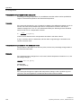
Analyzer section.........................................................................................................................104
Design of the analyzer section...................................................................................................104
Disassembling the analyzer section ..........................................................................................106
Removing the sample gas restrictor ..........................................................................................108
6.3
Replacement of motherboard and add-on board.......................................................................108
6.4
Replacing fuses .........................................................................................................................109
6.5
Cleaning the device ...................................................................................................................110
6.6
6.6.1
6.6.2
Maintenance requests and fault messages ...............................................................................110
Maintenance requests................................................................................................................111
Faults .........................................................................................................................................113
Spare parts list....................................................................................................................................... 115
7.1
General information ...................................................................................................................115
7.2
Analyzer section.........................................................................................................................117
7.3
Electronics..................................................................................................................................118
7.4
Gas channel ...............................................................................................................................119
OXYMAT 61
Operating Instructions, 12/2011, A5E00123067-02
5
Table of contents
8
9
Technical specifications ......................................................................................................................... 123
8.1
General technical specifications ............................................................................................... 123
8.2
Reference gases ....................................................................................................................... 126
8.3
Zero point error ......................................................................................................................... 127
8.4
Materials used in the sample gas channel................................................................................ 128
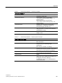
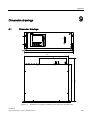
Dimension drawings .............................................................................................................................. 129
9.1
A
B
Appendix................................................................................................................................................ 131
A.1
EC Declaration of Conformity.................................................................................................... 131
A.2
Return delivery .......................................................................................................................... 133
ESD Directives....................................................................................................................................... 135
B.1
C
Dimension drawings.................................................................................................................. 129
ESD guidelines.......................................................................................................................... 135
List of abbreviations/acronyms .............................................................................................................. 137
C.1
List of abbreviations .................................................................................................................. 137
Glossary ................................................................................................................................................ 141
Index...................................................................................................................................................... 149
OXYMAT 61
6
Operating Instructions, 12/2011, A5E00123067-02
General information
1.1
1
Device model and validity
You have purchased the OXYMAT 61, a device that that undergoes continuous development
and therefore can vary in functionality and software release in comparison to other devices
of the same type.
This manual describes the OXYMAT 61 gas analyzer with the software release 4.8.3.
1.2
Information for our customers
Before beginning work with this device, please read this manual! It contains important
information and data whose observation ensures proper device function and saves you
servicing costs. The manual will help you to operate the device more easily and efficiently,
allowing you to achieve reliable results.
1.3
General information
This device left the factory in a safe and proper condition and has been tested. In order to
maintain this condition and to ensure safe operation of this product, it should only be used in
the manner described by the manufacturer. Furthermore, proper transportation, storage,
installation, operation and maintenance of the device are vital for ensuring correct and safe
operation.
This manual contains the information required for the intended use of the described product.
It is addressed to technically qualified personnel who are specially trained or who have the
relevant knowledge of automation technology (measuring and control systems).
Knowledge and technically correct implementation of the safety notes and warnings
contained in this manual are required for safe installation and commissioning, as well as for
safety during the operation and maintenance of the described product. Only qualified
personnel have the required professional knowledge for correctly interpreting the generally
valid safety notes and warnings in this manual in each specific case and to act accordingly.
This manual is an inherent part of the scope of delivery, despite the fact that it can be
ordered separately for logistic reasons.
OXYMAT 61
Operating Instructions, 12/2011, A5E00123067-02
7
General information
1.4 Special information and warnings
Due to the variety of technical details, it is not possible to consider every single detail for all
versions of the described product and for every conceivable case in the set-up, operation,
maintenance and use in systems. For further information, or in the case of problems which
are not covered in enough detail in this document, please request the required information
from your local or responsible Siemens regional office.
Note
In particular, before using the device for new research and development applications, we
recommend that you first contact us to discuss the application in question.
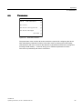
1.4
Special information and warnings
This manual provides you with information on using, installing, operating, and maintaining
the device.
Pay particular attention to all special information and warnings. Information of this type is set
apart from the rest of the text and is marked with the corresponding pictograms. This
information provides you with useful tips and helps avoid maloperations.
OXYMAT 61
8
Operating Instructions, 12/2011, A5E00123067-02
General information
1.5 Proper use
1.5
Proper use
Proper use within the context of this manual, means that the product may be used only for
the applications described in the catalog or the technical description, and only in combination
with the equipment, components and devices of other manufacturers recommended or
permitted by Siemens.
The product described in this manual has been developed manufactured, tested and
documented in compliance with relevant safety standards. When the handling rules
described for the configuration, installation, proper operation and maintenance, as well at the
safety guidelines are adhered to, therefore, there is normally no risk to the health of persons
or in respect to damage to property.
This device was designed to ensure safe isolation of the primary and secondary circuits. Low
voltages that are connected must therefore also be generated with safe isolation.
WARNING
Dangerous contact voltage
After removing the housing or protection against direct contact or after opening the system
cabinet, certain parts of of this device/system will be exposed that can carry hazardous
voltage. Therefore, only appropriately qualified persons are permitted to perform work
within this device. These persons must be thoroughly familiar with all sources of danger
and service activities in accordance with these operating instructions.
1.6
Qualified Personnel
Qualified personnel are people who are familiar with the installation, mounting,
commissioning, and operation of the product. These people have the following qualifications:
● They are authorized, trained or instructed in operating and maintaining devices and
systems according to the safety regulations for electrical circuits, high pressures and
aggressive as well as hazardous media.
● For explosion-proof devices: they are authorized, trained, or instructed in carrying out
work on electrical circuits for hazardous systems.
● They are trained or instructed in maintenance and use of appropriate safety equipment
according to the safety regulations.
OXYMAT 61
Operating Instructions, 12/2011, A5E00123067-02
9
General information
1.7 Notes on warranty
1.7
Notes on warranty
The contents of this manual shall not become part of or modify any prior or existing
agreement, commitment or legal relationship. The sales contract contains all obligations on
the part of Siemens as well as the complete and solely applicable warranty conditions. Any
statements regarding device versions described in the manual do not create new warranties
or modify the existing warranty.
The content reflects the technical status at the time of publishing. Siemens reserves the right
to make technical changes in the course of further development.
1.8
Delivery information
The respective scope of delivery is listed on the shipping documents – enclosed with the
delivery – in accordance with the valid sales contract.
When opening the packaging, please observe the corresponding information on the
packaging material. Check the delivery for completeness and undamaged condition. In
particular, you should compare the Order No. on the rating plates with the ordering data, if
available.
If possible, please retain the packaging material, since you can use it again in case of return
deliveries.
1.9
Standards and regulations
As far as possible, the harmonized European standards were the basis for the specification
and production of this device. If no harmonized European standards have been applied, the
standards and regulations for the Federal Republic of Germany are valid.
When this product is used beyond the scope of these standards and regulations, the valid
standards and regulations of the country of the operating company apply.
OXYMAT 61
10
Operating Instructions, 12/2011, A5E00123067-02
Description
Description
2.1
2
Area of application
The OXYMAT 61 gas analyzers use a measuring principle based on the paramagnetic
alternating pressure method and are used to measure oxygen in gases.
NOTICE
The OXYMAT 61 is not suited for measuring flammable, toxic and corrosive gases.
Application examples
Measurement of oxygen
● For boiler control in incineration plants
● For quality monitoring in ultra-pure gas
● For environmental protection
● For monitoring of process exhaust gas
● For process optimization
OXYMAT 61
Operating Instructions, 12/2011, A5E00123067-02
11
Description
2.1 Area of application
Important features
● Four freely configurable measuring ranges, also with suppressed zero point, all
measuring ranges are linear
● Electrically isolated measured value output 0/2/4 to 20 mA
● Selectable automatic or manual measuring range switching; remote switching is also
possible
● Measured values can be stored during calibration
● Wide range of selectable time constants (static/dynamic noise suppression); i.e. the
response time of the device can be adapted to the respective measuring task
● Simple handling through menu-guided operation according to NAMUR recommendation
● Fast response time
● Low long-term drift
● Reference gas supply either externally (N2, O2 or air, approx. 2000 to 4000 hPa via
sample gas pressure) or via built-in reference gas pump (ambient air)
● Two control levels with separate authorization codes to prevent unintentional and
unauthorized operator intervention
● External pressure sensor can be connected for correction of variations in the process gas
pressure in the range 800 to 1200 hPa (absolute)
● Automatic measuring range calibration can be configured
● Fieldbus connection (optional)
● Monitoring of sample gas (optional)
● Monitoring of reference gas (only with version with internal reference gas pump)
● Variety of narrow measuring ranges, depending on version 2.0 % or 5.0 % O2
● Easy device replacement since electric connections can be simply disconnected from the
device
● 19" rack unit with 4 height units (U) for installation in swivel frame
● 19" rack unit with 4 U for installation in cabinets, with or without telescopic rails
● Front plate can be swung down for servicing purposes (laptop connection)
● Internal gas channels: Hose made of FKM (Viton)
● Connections for sample gas: Pipe diameter 6 mm or 1/4"
● Sample chamber of stainless steel (mat. no. 1.4571)
OXYMAT 61
12
Operating Instructions, 12/2011, A5E00123067-02
Description
2.2 Design
2.2
Design
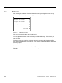
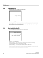
Display and control panel
● Large LCD for simultaneous display of:
– Measured value (digital and analog displays)
– Status line
– Measuring ranges
● Contrast of the LCD adjustable via the menu
● Permanent backlighting with LED
● 5-digit measured value display (decimal point counts as digit)
● Washable membrane keyboard/front panel
● Menu-guided operation for parameter assignment, configuration and calibration
● Operating help in plain text
● Graphic display of concentration trend; programmable time intervals
Inputs and outputs
● Two analog inputs configurable (e.g. interference correction or external pressure sensor)
● Six relay outputs, freely configurable (e.g. faults, maintenance request, calibration, limit
alarm, external solenoid valves)
● Six digital inputs, freely configurable (e.g. for measurement range switchover, processing
of external signals from sample preparation)
● Can be extended by eight additional digital inputs and eight additional relay outputs for
automatic calibration with max. four calibration gases
Communication
● RS485 (standard)
● Optionally available:
– AK interface for the automotive industry with extended functions
– Converter for RS232, USB and Ethernet
– Integration in networks via PROFIBUS DP/PA interface
– SIPROM GA software as the service and maintenance tool
OXYMAT 61
Operating Instructions, 12/2011, A5E00123067-02
13
Description
2.2 Design
SIEMENS
CAL
CTRL
CODE
1O.5O
O
% vol
O2
1 2 3 4
25
+/-
7
8
9
.
4
5
6
O
1
2
3
CLEAR
ESC
INFO
ENTER
MEAS
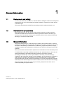
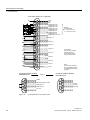
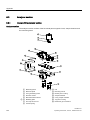
OXYMAT 61
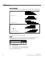
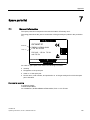
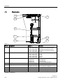
1
Status line for display of analyzer state (configurable)
2
Two code levels according to NAMUR (maintenance and specialist levels)
3
Display of activated measuring ranges
4
Five softkeys for menu control
5
ESC key for returning to previous input step, with application of any changes made
6
INFO key for help functions for the current menu
7
MEAS key for returning to measuring mode
8
CLEAR key to delete numerical inputs
9
ENTER key to accept numerical values
10
Numerical keypad for entering numerical values
11
Display of start-of-scale and full-scale values
12
Display of concentrations as digits and bars
Figure 2-1
Membrane keyboard and graphic display
OXYMAT 61
14
Operating Instructions, 12/2011, A5E00123067-02
Description
2.3 Communication interface
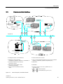
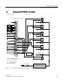
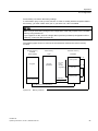
2.3
Communication interface
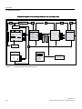
&RQWDLQHU$
3&
6DPSOHJDV
SUHVVXUH2
5HPRWHFRQWURO
2;<0$7
&2&+
6,3520*$
ODSWRS
&212
0DLQWHQDQFHFHQWHU
/RFDO
FRQWURO
8/75$0$7(
FKDQQHOXQLW
56(/$1
6DPSOHJDV
SUHVVXUH2
&2
&262
122
2VDPSOHJDV
SUHVVXUH
2;<0$7)
8/75$0$72;<0$7(
8/75$0$7
&RQWDLQHU%
&RQWDLQHU&
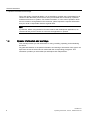
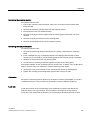
ᅾ(/$1 (FRQRPLFDO/RFDO$UHD1HWZRUN
ᅾ 5HPRWHWUDQVPLVVLRQYLDPRGHP
ᅾ1HWZRUNLQJRIYDULRXVDQDO\]HUV
8/75$0$72;<0$72;<0$78/75$0$7
ᅾ8SWRFKDQQHODGGUHVVHVLQWHUIDFHVFDQEHXVHGIRUPHDVXUHG
YDULDEOHVFRQFHQWUDWLRQVSUHVVXUHVWHPSHUDWXUHVHWF
ᅾ&HQWUDOL]HGPDLQWHQDQFHE\FRXSOLQJWR
KLJKHUOHYHOFRPSXWHU
ᅾ6,3520*$
ᅾ0HDVXUHPHQWGDWDDYDLODEOHLQ$6&,,
IRUPDWIRUIDVWSURFHVVLQJ
ᅾ352),%86
ᅾ5HPRWHFRQWURODQGGRZQORDGRIUHFRUGV
YLD3&
ᅾ7HFKQRORJ\56EDXGUHSHWLWLRQUDWHV
UDQJHXSWRP
ᅾ &KDQQHODGGUHVVHV
DQG &RQWURODGGUHVVHVHJIRU3&HWF
Figure 2-2
Various analyzers, networked with 485
OXYMAT 61
Operating Instructions, 12/2011, A5E00123067-02
15
Description
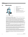
2.4 Principle of operation
2.4
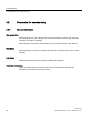
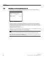
Principle of operation
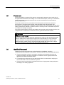
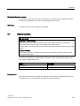
ΔP
O2
1
Reference gas channel
2
Restrictors
3
Reference gas channels
4
Microflow sensor for measured signal
5
Sample gas inlet
6
Sample chamber
7
Paramagnetic measurement effect
8
Electromagnet with alternating field strength
9
Sample gas and reference gas outlet
O2
O2
O2
O2
OXYMAT 61, principle of operation
In contrast to almost all other gases, oxygen is paramagnetic. This property is utilized as a
measuring effect by the OXYMAT 61 channel.
Due to their paramagnetism, oxygen molecules in an inhomogeneous magnetic field always
move in the direction of increased field strength. When two gases with different oxygen
contents meet in a magnetic field, a pressure difference is produced between them.
In the case of OXYMAT 61, one gas (1) is a reference gas (N2, O2 or air), the other is the
sample gas (5). The reference gas is introduced into the sample chamber (6) through two
channels (3). One of these reference gas streams meets the sample gas within the area of a
magnetic field (7). Because the two channels are connected, the generated pressure
difference creates a flow. This flow is converted into an electric signal by a microflow sensor
(4). The pressure difference is proportional to the difference in the oxygen content of sample
and reference gas.
The microflow sensor consists of two nickel-plated grids, which are heated to approximately
120 °C. Together with two supplementary resistors they form a Wheatstone bridge. The
pulsating flow results in a change in the resistance of the Ni grids. This leads to an offset in
the bridge which is proportional to the oxygen content of the sample gas.
Because the microflow sensor is located in the reference gas stream, the measurement is
not influenced by the thermal conductivity, the specific heat or the internal friction of the
sample gas. This also provides a high degree of corrosion resistance because the microflow
sensor is not exposed to the direct influence of the sample gas.
A magnetic field with alternating strength (8) prevents detection of the background flow in the
microflow sensor, enabling measurement to be performed independent of the sample
chamber position and thus also independent of the location where the gas analyzer is used.
The sample chamber is directly in the sample channel and has a small volume, and the
microflow sensor is a low-lag sensor. This results in a very fast response time for the
OXYMAT 61.
OXYMAT 61
16
Operating Instructions, 12/2011, A5E00123067-02
Mounting and connecting
Mounting and connecting
3.1
3
Safety instructions
DANGER
Explosion hazard
The analyzer must not be operated in potentially explosive atmospheres. The supply of
gases with combustible components in concentrations above the lower explosive limit (LEL)
must be clarified in consultation with the relevant hazard experts and is ultimately the
responsibility of the operator.
WARNING
Dangerous contact voltage
Certain parts of this device are under dangerous voltage. In order to avoid contact with live
parts, the housing must be closed and grounded upon completion of all assembly and
installation work.
Failure to comply with this can result in death, personal injury and/or damage to property.
WARNING
Release of hazardous gases
Gases may be released if there are leaks in the sample gas channel. For this reason, toxic
and corrosive gases are not allowed to be be measured with this device.
Failure to comply with this can result in death, personal injury as well as damage to
property and the environment.
CAUTION
Incorrect mounting
The device can be damaged, destroyed or its functionality impaired through improper
mounting.
• Before installing ensure there is no visible damage present on the device.
• Make sure that process connectors are clean, and suitable gaskets and glands are
used.
• Mount the device using suitable tools. Refer to the information in "Technical data" , for
example installation torques requirements.
OXYMAT 61
Operating Instructions, 12/2011, A5E00123067-02
17
Mounting and connecting
3.2 Installation requirements
3.2
Installation requirements
Vibration
Select an installation location which is as vibration-free as possible. If you install the device
in a cabinet or in desktop housing, you must hang it on support rails. It is not sufficient to
only secure the front side, since the intrinsic weight of the device creates too much load on
the chassis.
Temperature
Ensure sufficient ventilation between the devices if you install them in control cabinets.
If the device is installed outdoors, it must be protected from direct sunlight.
Ensure that the permissible ambient temperature range of 5 to 45 °C is maintained during
operation (see Technical Specification section).
Magnetic fields
Magnetically sensitive devices should not be installed in close proximity of OXYMAT 61
since it is inherently emits stray magnetic fields. Depending on the sensitivity, distances up
to 50 cm are required (see also Function 57).
OXYMAT 61
18
Operating Instructions, 12/2011, A5E00123067-02
Mounting and connecting
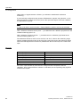
3.3 Connections
3.3
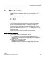
Connections
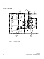
6DPSOHJDVRXWOHW
6DPSOHJDVLQOHW
SLQFRQQHFWRU'LJLWDO
LQSXWVDQGDQDORJLQSXWV
DQGRXWSXWV
SLQ
FRQQHFWRU
56
5HIHUHQFHJDVLQOHW
3XUJHJDV
LQOHW
SLQ
LQWHUIDFHFRQQHFWRU
RSWLRQDO
HJ352),%86
3RZHUVXSSO\
FRQQHFWLRQ
DQGPLQLDWXUHIXVHV
*DVFRQQHFWLRQV1R]]OHPPRU
Figure 3-1
SLQFRQQHFWRU'LJLWDO
LQSXWVDQGUHOD\RXWSXWV
RSWLRQDO
SLQFRQQHFWRU'LJLWDO
LQSXWVDQGUHOD\RXWSXWV
Back side with gas and electrical connections
OXYMAT 61
Operating Instructions, 12/2011, A5E00123067-02
19
Mounting and connecting
3.3 Connections
3.3.1
Gas connections and internal gas flow diagram
3.3.1.1
Sample gas line
Connector stems with a pipe diameter of 6 mm or 1/4" are provided for gas connections. For
the gas supply and discharge from the device, you need to select a suitable material for the
sample gas.
CAUTION
Dynamic pressure in the sample gas channel
The device must be operated in such a way that the sample gas pressure in the analyzer
does not accumulate. When several devices are connected in series, you must ensure that
there are no restrictions in the gas channels of the downstream devices (free exhaust gas
flow). You must remove any sample gas restrictors installed in the device. The only
restrictor that can be retained is one between the sample gas line and the first gas analyzer
unit.
After removing the sample gas restrictors, the sample gas monitoring (pressure switches)
of the downstream analyzers will be inoperable. To avoid error messages, you must have
disable the corresponding error messages ("Gas flow rate is too low") in the configuration
function of the software (section 5.6.18, Function 87 (Page 101), Error S16). You should
also note in this case that the assignment of a relay to the "Sample gas flow" error
message has no function.
If the sample gas flows to an exhaust gas line, you must note the following:
• The flow resistance in the exhaust gas line should be kept as low as possible with a line
as short as possible or with a large diameter junction.
• The exhaust gas line must be free of rapid pressure fluctuations. If this is not the case,
either a special exhaust gas line must be installed, or a damping vessel (> 1 l) with
restrictor must be installed between the device and exhaust gas line (pneumatic low
pass).
OXYMAT 61
20
Operating Instructions, 12/2011, A5E00123067-02
Mounting and connecting
3.3 Connections
3.3.1.2
Reference gas line
The connection stems for the reference gas has a pipe diameter of 6 mm or 1/4".
The reference gas line must be as short as possible and have a small cross-section.
If you use N2 or O2 as a reference gas, you must use a metal pipe as the supply line. If air is
used as the reference gas, it is recommended to install a dryer attachment in the intake to
avoid volume errors in comparison to the gas side that can be caused by air humidity.
If you subsequently convert the device to a different reference gas supply, ensure that only
trained service personnel perform the replacement work for the connector stems and the
reference gas restrictor.
3.3.1.3
Pressure sensor
The device has an internal pressure sensor for correcting the effect of pressure on the
measured value.
It is firmly mounted in the analyzer unit and directly measures sample gas pressure through
the reference gas supply. The pressure sensor is therefore not involved in the installation.
3.3.1.4
Gas preparation
To prevent contamination of parts from contact with the sample gas, which can thus
influence the measurement, the sample gas must be sufficiently prepared before it is
introduced in the device.
The following components are usually located upstream from the sample gas inlet of the
device:
● Gas sampling device
● Sample gas cooler
● Filter
● A gas suction pump
Depending on the composition of the sample gas, you may need additional equipment such
as a wash bottle, additional filters and pressure reducers.
Also provide for the removal of corrosive components or components that interfere with the
measurement process by using appropriate absorption filters.
OXYMAT 61
Operating Instructions, 12/2011, A5E00123067-02
21
Mounting and connecting
3.3 Connections
*DVVDPSOHSUREHKHDWHGLIUHTXLUHG
6DPSOHJDVOLQHKHDWHGLIUHTXLUHG
*DVFRROHU
)LOWHUWUDSLIUHTXLUHG
6DPSOHJDVSXPS
&RQWUROYDOXH
)ORZLQGLFDWRULIGHYLFHKDVQR
VDPSOHJDVPRQLWRULQJ
7RVDPSOHJDVLQSXW
&RQGHQVDWLRQGUDLQ
Figure 3-2
3.3.1.5
Example of gas preparation
Gas flow diagram
)
1
3
3
Figure 3-3
Gas path OXYMAT 61 with installed reference gas pump
OXYMAT 61
22
Operating Instructions, 12/2011, A5E00123067-02
Mounting and connecting
3.3 Connections
F
14
P
7
8
1
P
15
2
6
4
5
13
9
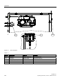
Figure 3-4
OXYMAT 61 gas channel, with reference gas connection 3 000 to 5 000 hPa absolute
Key for gas flow diagrams
1 Sample gas inlet
9 Purging gas
2 Sample gas outlet
10 Restrictor in reference gas channel (outlet)
3 n.c.
11 Pressure switch for reference gas monitoring
4 Reference gas inlet
12 Pump
5 Restrictor in reference gas channel
13 Filter
6 Analyzer section
14 Flow indicator in sample gas channel (optional)
7 Restrictor in sample gas channel
15 Pressure sensor
8 Pressure switch in sample gas channel (option)
OXYMAT 61
Operating Instructions, 12/2011, A5E00123067-02
23
Mounting and connecting
3.3 Connections
3.3.2
Electrical connections
3.3.2.1
Mains connection
WARNING
Dangerous contact voltage
Danger of electric shock in case of incorrect connection.
• For the electrical connection specifications, refer to the information in Chapter
"Technical specifications (Page 123)".
• At the mounting location of the device observe the applicable directives and laws for
installation of electrical power installations with rated voltages below 1000 V.
● The device comes with an appliance plug which may only be connected to the mains
supply line by qualified personnel. The mains supply line must comply with the valid
regulations and conditions for the place of installation and be provided with a protective
conductor which lies at the potential of the enclosure. The cross-section of each wire
must be ≥ 1 mm². Connect the phase conductor to the marked position in the plug.
● Install the mains line separately from the signal lines.
● Provide a mains disconnection device in the direct vicinity of the device (for load rating,
see rating plate). It must be readily accessible and marked.
● Check whether the existing mains voltage agrees with the mains voltage specified on the
rating plate.
OXYMAT 61
24
Operating Instructions, 12/2011, A5E00123067-02
Mounting and connecting
3.3 Connections
3.3.2.2
Connection of the signal cables
WARNING
Inadequate signal lines
If signals (e.g. 4 to 20 mA analog output) are to be introduced into a hazardous area of
zone 1, they must be intrinsically-safe. Additional upgrading or retrofitting of the device with
energy-limiting modules is also required in this case.
Failure to comply with this can result in death, serious personal injury and/or damage to
property.
The Ex marking of these energy-limiting modules must be clearly visibly on the device.
WARNING
Only connect the signal lines to devices which have reliable electric isolation from their
power supply.
● The connection lines to the relay outputs, the digital inputs, the analog inputs and the
analog outputs must be shielded.
● The reference ground of the analog inputs is the potential of the housing.
● The analog output is floating.
OXYMAT 61
Operating Instructions, 12/2011, A5E00123067-02
25
Mounting and connecting
3.3 Connections
● As a measure to suppress sparking across the relay contacts (e.g. limit relays), RC
elements must be connected as shown in the following figure. Note that the RC element
results in a drop-out delay for an inductive component (e.g. solenoid valve). The RC
element should be sized according to the following rule of thumb:
R [ Ω ] ≈ 0.2 x RL [ Ω]; C[ μF ] ≈ IL [ A ]
You must also use a non-polarized capacitor for the RC element.
&RQQHFWRU68%')
0
3RZHUVXSSO\
9PD[
5
,/
5/
&
5>˖@ป[5 />˖@
&>˩)@ป, />$@
0
Figure 3-5
Example of spark suppression on a relay contact
When operated with direct current, a spark suppression diode can be installed instead of the
RC element.
● Connect the signal lines to the SUB-D plug connectors at the rear of the device.
● Refer to the ELAN interface description (Order No. C79000-B5200-C176 German,
C79000-B5276-C176 English) for details on the interface cable.
OXYMAT 61
26
Operating Instructions, 12/2011, A5E00123067-02
Mounting and connecting
3.3 Connections
3.3.2.3
Pin assignments
&RQQHFWRU68%')56
0
*1'
9
0
*1'
5B/HYHO1
1&
5'7'1
5'7'3
5B/HYHO3
1&
1&
*1'
7HUPLQDWLQJUHVLVWRUVIRUWKHEXVFDQEH
FRQQHFWHGWRSLQVDQG
&RQQHFWRU68%')
'LJLWDOLQSXWV
$QDORJLQSXWVDQDORJRXWSXWV
0
0
0
0
*1'
1&
1&
$QDORJRXWSXW3
$QDORJRXWSXW1
1&
1&
$QDORJLQSXW3
$QDORJLQSXW1
$QDORJLQSXW3
$QDORJLQSXW1
'LJLWDOLQSXW3
'LJLWDOLQSXW3
'LJLWDOLQSXWWR1
*1'
$QDORJRXWSXWVIORDWLQJ
PXWXDOO\LVRODWHGDVZHOO5 /ืവ
&RUUHFWLRQRI
FRPSUHVVHGRU
LQWHUIHULQJJDV
&RUUHFWLRQRI
LQWHUIHULQJJDV
$QDORJLQSXWV
QRQIORDWLQJWR
P$വRU
WR9ORZ
LPSHGDQFH
&RQQHFWRU68%')
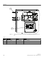
0
'LJLWDOHLQJ¦QJH5HODLVDXVJ¦QJH
*1'
'LJLWDOLQSXW3
'LJLWDOLQSXW3
'LJLWDOLQSXW3
'LJLWDOLQSXW3
'LJLWDOLQSXWWR1
5HOD\
5HOD\
5HOD\
5HOD\
&RQWDFWORDG
PD[9$$&'&
UHOD\FRQWDFWVVKRZQ
GHHQHUJL]HGUHOD\FRLO
5HOD\
0
Figure 3-6
'LJLWDOLQSXWV
9WR9
9WR9
IORDWLQJYLDRSWRFRXSOHU
5HOD\
*1'
1RWH
7KHZLUHDQGFRQQHFWRUPXVW
EHVKLHOGHGDQGEH
FRQQHFWHGWRWKHKRXVLQJ
SRWHQWLDO
Motherboard pin assignments
OXYMAT 61
Operating Instructions, 12/2011, A5E00123067-02
27
Mounting and connecting
3.3 Connections
&RQQHFWRU68%')RSWLRQDO
0
*1'
1&
1&
'LJLWDOLQSXW3
'LJLWDOLQSXW3
'LJLWDOLQSXW3
'LJLWDOLQSXW3
'LJLWDOLQSXW3
'LJLWDOLQSXW3
'LJLWDOLQSXW3
'LJLWDOLQSXW3
'LJLWDOLQSXWWR1
)ORDWLQJ
YLDRSWRFRXSOHU
9WR9
9WR9
5HOD\
5HOD\
5HOD\
5HOD\
&RQWDFWORDG
PD[9$$''&
WKHUHOD\KDV]HUR
FXUUHQWIRUWKHVKRZQ
UHOD\FRQWDFWSRVLWLRQ
5HOD\
5HOD\
5HOD\
5HOD\
1RWH
7KHZLUHDQGFRQQHFWRU
PXVWEHVKLHOGHGDQGEH
FRQQHFWHGWRWKHKRXVLQJ
SRWHQWLDO
0
&RQQHFWRU68%');
352),%86'3
*1'
2SWLRQDO
'*1'
&1753GLUHFWLRQFRQWURO
5['7['3%
5['7['1$
939
Figure 3-7
&RQQHFWRU68%'0;
352),%863$
3D1
3D3
3D1
Pin assignments of the add-on board
OXYMAT 61
28
Operating Instructions, 12/2011, A5E00123067-02
Mounting and connecting
3.4 Example of AUTOCAL connection
3.4
Example of AUTOCAL connection
)XQFWLRQLQWKHGHYLFH
&RQQHFWLRQHQG
9GR
&RQQHFWRU68%')RSWLRQDO
=HUR
JDV
0
9GF
&DOLEUDWLRQ
JDV
9GF
&DOLEUDWLRQ
JDV
&DOLEUDWLRQ
JDV
5HOD\
9GF
5HOD\
&DOLEUDWLRQ
JDV
5HOD\
0
9GF
5HOD\
5HOD\
5HOD\
9SRZHU
VXSSO\ปPD[
,QWKHUHOD\FRQWDFWSRVLWLRQVKRZQ
WKHUHOD\VDUHGHHQHUJL]HG
GRGHHQHUJL]HGRSHQ
GFGHHQHUJL]HGFORVHG
90VDPSOHJDVYDOYH
6DPSOH
JDV
90GF
6DPSOHJDVLQOHW
*DVSUHSDUDWLRQHOHPHQWV
Figure 3-8
Connector pin assignment and valve diagram of an AUTOCAL connection
OXYMAT 61
Operating Instructions, 12/2011, A5E00123067-02
29
Commissioning
4.1
4
Safety instructions
DANGER
Explosion hazard
The analyzer must not be operated in potentially explosive atmospheres. The supply of
gases with combustible components in concentrations above the lower explosive limit (LEL)
must be clarified in consultation with the relevant hazard experts and is ultimately the
responsibility of the operator.
WARNING
Dangerous contact voltage
Certain parts of this device are under dangerous voltage. In order to avoid contact with live
parts, the housing must be closed and grounded upon completion of all assembly and
installation work.
Failure to comply with this can result in death, personal injury and/or damage to property.
WARNING
Release of hazardous gases
Gases may be released if there are leaks in the sample gas channel. For this reason, toxic
and corrosive gases are not allowed to be be measured with this device.
Failure to comply with this can result in death, personal injury as well as damage to
property and the environment.
OXYMAT 61
Operating Instructions, 12/2011, A5E00123067-02
31
Commissioning
4.2 Preparation for commissioning
4.2
Preparation for commissioning
4.2.1
General information
Gas preparation
Make all devices in the gas channel upstream from the analyzer ready for operation (e.g.:
gas sampling devices, gas cooling device, condensate vessels, filters and any connected
controllers, recorders or indicators.
Read carefully the instructions and information in the operation manuals of the devices!
Operation
Before switching on the device, familiarize yourself with its operation (see section 5 of this
manual)!
Interfaces
Make sure that all interfaces are properly assigned and configured.
Electrical connections
Make sure that all electrical connections have been correctly made. Read also the
information in the "Electric connection" section.
OXYMAT 61
32
Operating Instructions, 12/2011, A5E00123067-02
Commissioning
4.2 Preparation for commissioning
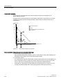
4.2.2
Selection of the reference gas
When you select the reference gas, you must ensure that the various measurement spans
have at least one common point. This point is then defined as 'physical zero point'. This
applies to all measuring ranges. Once this point is known, the reference gas can be
selected.
This is explained by the following example:
There are four measuring ranges:
● 17 - 22 % O2
● 15 - 25 % O2
● 0 - 25 % O2
● 0 -100 % O2
These four measurement ranged have the spans from 17 to 22 % O2 in common. The
physical zero point should lie within this range. Air (20.95 % O2%) is suitable as the
reference gas in this case.
An exception to this principle is possible if the smallest measuring span ≥5 % O2 and the
distance to the reference gas is not more than 20 % O2. Then, the physical zero point may
be located outside the measuring range. In this case, however, the pressure correction (see
Function 82 in section 5) must be activated, since there a pressure relationship due to the
large zero point offset.
The purity of the reference gas has to be appropriate for the measuring task.
Installing the reference gas connection
The reference gas connection is made depending on the order:
● Air (low pressure variant)
Air as the reference gas is sucked in with the internal pump. When the analyzer is
mounted in a cabinet, you must therefore ensure that the air sucked in is supplied from
outside the cabinet.
● Nitrogen, oxygen, air (high pressure variant)
Pay attention to the purity of the gas (4.6)!
The supply is here comes from a compressed gas cylinder with a pressure setting of
2000 to 4000 hPa over the sample gas pressure. A sintered metal frit (porous filter) is in
the coupling to prevent entry of dirt particles into the analyzer.
OXYMAT 61
Operating Instructions, 12/2011, A5E00123067-02
33
Commissioning
4.2 Preparation for commissioning
Introducing reference gas
Always introduce the reference gas before beginning the measurements. Reference gas
should always continue to flow even if the measurements are temporarily interrupted. The
increased consumption caused by this is negligible when compared to reference gas line is
sealed.
Compressed gas cylinder
If the reference gas is taken from a compressed gas cylinder, the reference gas line must be
purged prior to commissioning. You must then check the line for leaks, because leakage
losses are often greater than the reference gas consumption. To do this, close the valve at
the compressed gas cylinder. If the pressure indicator at the reducer value of the gas
cylinder does not drop by more than 1000 hPa/min, the gas connection is sufficiently sealed.
The reference gas pressure must always be 2000 hPa or more above the sample gas
pressure.
Checking the reference gas flow
To do this, proceed as follows:
1. Close the sample gas inlet couplings.
2. Lay a hose with an internal diameter of 4 mm from the sample gas outlet nozzle into a
beaker filled with water.
3. Observe the glass.
The reference gas must be slow with 1 to 2 bubbles per second coming through the
water.
Checking for leaks in the sample gas channel with hosed devices
To do this, proceed as follows:
1. Close the reference gas connection.
2. Establish a pressure of approx. 100 hPa in the sample gas channel.
3. Wait about 1 minute.
During this time, the inflowing sample gas will adapt to the ambient temperature.
4. Note the pressure.
5. Wait another 15 minutes.
6. Note the pressure again.
The sample gas channel is sufficiently tight when the pressure has changed by no more
than 1 hPa (1 mbar) within these 15 minutes.
OXYMAT 61
34
Operating Instructions, 12/2011, A5E00123067-02
Commissioning
4.2 Preparation for commissioning
4.2.3
Initial commissioning
Switch on the power supply
After you have ensured that all connections have been made and there are no leaks, switch
on the device. After a short period, the measured value display appears on the operator
display. The status display is located above this in the top row (for details on the operator
display see section 5.1).
The measuring head is in the warm-up phase during the first five minutes. During this time,
the display signals CTRL (function check).
Setting the measuring span
Specify the desired spans (measuring range full-scale value - measuring range start-of-scale
value) with function 41. The start-of-scale or full-scale values are assigned to the 0(2/4) or
20 mA of the analog output.
If you define multiple measurement ranges; we recommend that you set measurement range
1 for the smallest measuring span (MS)etc. In general, the following applies then:
MS1 < MS2 < MS3 < MS4
Setting the physical zero point
If the composition of test and reference gas are identical, their O2 difference is therefore zero
and there is no measuring signal. We refer to this as the physical zero point. Depending on
the reference gas, the physical zero point may therefore have any value between 0 and
100 % O2. The setpoint of the physical zero point is specified under function 22.
Setting the setpoint of the sensitivity
The setpoints of the sensitivity must be as far from the physical zero point as possible (at
least 60 % of the respective measuring span). The setpoint or setpoints are entered with
function 22. The calibration gases required for this must be made available for the
adjustment.
Selecting the calibration method
Set the calibration mode to total or single calibration using either function 23 or 52.
● Single calibration means that each measuring range is calibrated using its own calibration
gas.
● Total calibration means that you adjust one "leading measuring range" and all other
measuring ranges are "tracked" to this using the switching ratio.
When performing the calibration, ensure that the gas flows between 0.3 l/min and 1 l/min.
OXYMAT 61
Operating Instructions, 12/2011, A5E00123067-02
35
Commissioning
4.2 Preparation for commissioning
Calibrating the zero point
The physical zero point is calibrated with function 20. It is applied to all configured measuring
ranges.
Calibrating sensitivity
The sensitivity is calibrated with function 21.
Compensating the effect of temperature
The compensation of the temperature effect is stored permanently in the software (firmware)
for the OXYMAT 61. No further actions are required for this.
Noise suppression
Noise in the measured signal can be suppressed using function 50. This function allows you
to configure a low pass filter, which is assigned a time constant of maximum 100 s.
OXYMAT 61
36
Operating Instructions, 12/2011, A5E00123067-02
Commissioning
4.2 Preparation for commissioning
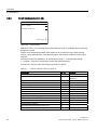
4.2.4
Calibration examples
The following examples reflect typical applications for the OXYMAT 61.
O2 monitoring in gases
Measurement task: Measurement of oxygen in N2.
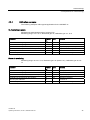
Measuring range: 0 to 5 % O2; Reference gas: N2; Calibration gas: 4.7 % O2
Procedure
Function
no.
Input
Remarks
Selection of measuring range start-of-scale value
41
0
0 ⇒ 0(2/4) mA
Selection of measuring range full-scale value
41
5
5 ⇒ 20 mA
Specification of the setpoint for the physical zero point
22
0
Setpoint for physical zero point
Specification of the setpoint for the sensitivity
22
4.7
Setpoint for sensitivity
Start zero point calibration
20
Introduce N2
Start sensitivity calibration
21
Introduce calibration gas
Room air monitoring
Measuring range: 15 to 21 % O2; Reference gas: Air (20.95 % O2); Calibration gas:15.3 %
O2
Procedure
Function
no.
Input
Remarks
Selection of measuring range start-of-scale value
41
15
15 ⇒ 0(2/4) mA
Selection of measuring range full-scale value
41
21
21 ⇒ 20 mA
Specification of the setpoint for the physical zero point
22
20.95
Setpoint for physical zero point
Specification of the setpoint for the sensitivity
22
15.3
Setpoint for sensitivity
Start zero point calibration
20
Introduce air
Start sensitivity calibration
21
Introduce calibration gas
OXYMAT 61
Operating Instructions, 12/2011, A5E00123067-02
37
Commissioning
4.2 Preparation for commissioning
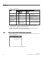
O2 measurement in flue gas
Measuring range: 0 to 10 % O2; Reference gas: Air; Calibration gas: N2
NOTICE
Reference gas out of range
In this example, the O2 content of the reference gas is not within the measuring range of up
to 10 % O2. Since the measuring span is greater than 5 %, however, an exception can be
made in the selection of the reference gas.
In this case, the pressure correction must be necessarily activated (see also Function 82 in
section 5)!
Procedure
Function
no.
Input
Remarks
Selection of measuring range start-of-scale value
41
0
0 ⇒ 0(2/4) mA
Selection of measuring range full-scale value
41
10
10 ⇒ 20 mA
Specification of the setpoint for the physical zero point
22
20.95
Setpoint for physical zero point
Specification of the setpoint for the sensitivity
22
0
Setpoint for sensitivity
Start zero point calibration
20
Introduce air
Start sensitivity calibration
21
Introduce N2
Purity monitoring of oxygen
Measuring range: 95 to 100 % O2; Reference gas: Pure O2; Calibration gas: 95.6 % O2
Procedure
Function
no.
Input
Remarks
Selection of measuring range start-of-scale value
41
95
95 ⇒ 0(2/4) mA
Selection of measuring range full-scale value
41
100
100 ⇒ 20 mA
Specification of the setpoint for the physical zero point
22
100
Setpoint for physical zero point
Specification of the setpoint for the sensitivity
22
95.6
Setpoint for sensitivity
Start zero point calibration
20
Introduce pure O2 (100 %)
Start sensitivity calibration
21
Introduce calibration gas
Detailed operating instructions for performing all the required testing functions are provided
in section 5 (Operation).
OXYMAT 61
38
Operating Instructions, 12/2011, A5E00123067-02
Operation
5
Operation
5.1
General information
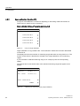
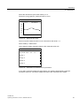
5.1.1
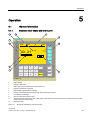
Measured value display and control panel
SIEMENS
CAL
CODE
CTRL
43.21 % VOL
O
O2
1 2 3 4
1OO.O
+/-
7
8
9
.
4
5
6
O
1
2
3
CLEAR
ESC
INFO
ENTER
MEAS
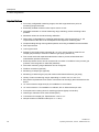
OXYMAT 61
1
Status display
2
Display of dimension
3
Status line (can be programmed under function 53)
4
Display of measured component
5
Buttons with varying function (softkeys)
6
Display of activated measuring ranges with the current range marked
7
Limit marker on bargraph
8
Start-of-scale and full-scale values
9
Analog measured value display (bar chart, graph of the measured value with the start-of-scale and full-scale value
of the current measuring range)
10
Measured value
Figure 5-1
Measured value display and control panel
OXYMAT 61
Operating Instructions, 12/2011, A5E00123067-02
39
Operation
5.1 General information
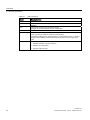
Table 5- 1
Button
Button meanings
Meaning/function
CLEAR
Clears the commenced number input
ENTER
Every number entered (except fast activation of a function) must be confirmed with
[ENTER].
ESC
Jumps back one step in the operating structure.
Changes are accepted without need for confirmation.
INFO
Information about current menu / current function
MEAS
Jump back from every position in the operating structure to the "Decoded display
mode" (you may be asked to confirm the entered data).
Pressing the [MEAS] button again changes to "Coded display mode", i.e. another
change in the "Operator control mode" requires the entry of the corresponding
code.
Softkey
Varying function; possible here are:
•
Submenu selection / function selection
•
Selection of a subfunction
•
ON/OFF switch function
OXYMAT 61
40
Operating Instructions, 12/2011, A5E00123067-02
Operation
5.1 General information
5.1.2
Device operating modes
Table 5- 2
Device operating modes
Mode
Properties
Coded display mode
•
Measured value display is
shown
•
Protected submenus can
only be reached by entering
a code
•
The current operating mode
of the device (except for
"Measure") is displayed in
the bottom line
•
Functional check not active
•
Measured value display is
shown
•
The submenus protected by
the entered code are
accessible
•
The current operating mode
of the device (except for
"Measure") is displayed in
the bottom line
•
Functional check active
•
Measured value can be
influenced
•
Menu or function is
displayed
•
Settings and inputs can be
made
•
Functional check active
•
Measured value can be
influenced
Decoded display mode
Operator control mode
Remarks
The device only supplies
reliable measured values in this
mode, as far as it's in the
"Measure" operating mode.
From the operator control mode,
you can reach this mode by
pressing the [MEAS] button
twice.
From the operator control mode,
you can reach this mode by
pressing the [MEAS] button
once and confirming or
discarding the made entries.
From "Coded display mode" you
can reach this mode by entering
the code of the corresponding
operation level.
In this mode, you can
configure/calibrate the device.
OXYMAT 61
Operating Instructions, 12/2011, A5E00123067-02
41
Operation
5.1 General information
Schematic diagram of the operating sequence with operating modes
&KDQJHVDUH
DFFHSWHG
MEAS
ESC
ESC
ESC
ESC
0HDVXUHPHQW
PRGH
CAL
CTRL
Code
-------------
-----------------------
-------------
-----------------------
-------------
Measuring ranges
Parameters
1 2 3 4
Configuration
2SHUDWLRQPRGH
ppm C1
1,O
Functions
,QSXWFRGH
$QDO\]HULVFRGHG
O,O
Functions menu
------------
Calibration
THC
O.35
Main menu
Diagnosis
-------------------------
'LVSOD\PRGH
MEAS
Query (only
following changes)
Accept
modifications?
)XQFWLRQDOFKHFN
UHOD\&75/
IXQFWLRQ
Yes
No
0HDVXUHGYDOXH
PHPRU\IRUDQDORJ
RXWSXWIXQFWLRQ
RQO\IROORZLQJFKDQJHV
Figure 5-2
Operating sequence with operating modes
OXYMAT 61
42
Operating Instructions, 12/2011, A5E00123067-02
Operation
5.1 General information
5.1.3
Editing inputs
The values in the menus shown in this chapter are meant as examples.
An active input field is shown with colons (e.g.: 10:) as a limiter. The cursor blinks under the
number to be entered.
By pressing the [ENTER] button, you finish your input and the value is stored. If there are
several input fields on one function screen, the cursor positions itself at the next input field at
the same time.
Note
Confirm every entered value, even the last of several values in a function, before exiting the
function with [ENTER]!
With the [CLEAR] button, you can clear a number which you have begun to enter. The
cursor then jumps back to the first position of the input field.
Graphic symbols
■ = activated (ON state; also in status message in the status line)
□ = deactivated (OFF state; also in status message in the status line)
► = access a submenu/subfunction
● = trigger a function/subfunction (e.g. Start calibration...)
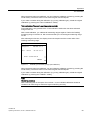
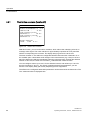
5.1.4
Operating sequence
CAL
CTRL
63.28
CODE
% Vol
O2
1 2 3 4
O.O
Figure 5-3
1OO.O
Measured value display
OXYMAT 61
Operating Instructions, 12/2011, A5E00123067-02
43
Operation
5.1 General information
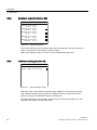
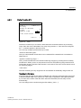
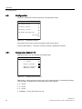
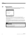
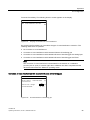
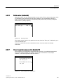
5.1.4.1
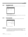
Introduction to the main menu
The device must be in measuring mode. The right side of the display field shows the
measured component, which is indicated with "MC" in the following illustrations of the
display. A right arrow [►] appears for it. This arrow indicates a softkey. The main menu can
be opened by pressing this softkey.
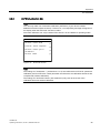
The main menu consists of the following commands (with the associated code level on the
right):
Function group
Code level
Analyzer status
Not coded
Calibration
Code of code level 1
Measuring ranges
Code of code level 1
Parameter
Code of code level 1
Configuration
Code of code level 2
The code of level 1 is factory set to "111", that of level 2 is factory set to "222".
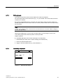
Main menu
MC
Analyzer status
Calibration
Measuring ranges
Parameters
Configuration
OXYMAT 61
44
Operating Instructions, 12/2011, A5E00123067-02
Operation
5.1 General information
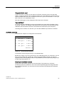
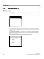
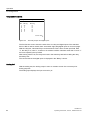
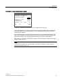
5.1.4.2
Entering a submenu
If you select a submenu by pressing the associated softkey, the code of the corresponding
operation level is queried once (exception: the submenu "Analyzer status" is freely
accessible; selecting this does not change the operating mode).
Decoding level 2 also decodes level 1.
By entering a corresponding code, the device switches to the operator control mode,
whereby the functional check is activated.
The functional check "CTRL" (shown in the status line of the measured value display) is
always activated by the device when an intervention endangers correct measurement, e.g.
when the code is entered. If you have configured a corresponding relay using function 71
with "Functional check", an extra signal is sent out via the relay contact together with the
decoding. This relay contact then signals every functional check activation, e.g. even the
warm-up phases and calibration states of the device.
Decoding also activates the measured value memory, providing you have configured this
using function 77.
The coding status of the device can be read in the status line of the measured value display
as a symbol "■ CODE" for "coded" or "□ CODE" for "decoded".
OXYMAT 61
Operating Instructions, 12/2011, A5E00123067-02
45
Operation
5.1 General information
5.1.4.3
Returning to display mode
You can use the [MEAS] key to jump back to "Decoded display mode" from any location in
"Operator control mode". Any input started is aborted.
Before jumping back, the following query appears:
Return to meas. mode
MC
Accept modifications?
YES
NO
Figure 5-4
Query before jumping back
● Press "YES" to accept changes permanently into the working memory of the parameter
memory or "NO" to discard the changes. The device then changes to "Decoded display
mode".
By pressing the [ESC] brings you back to the most recent function screen. Changes are
accepted here without a further query.
Coding the device
After jumping back to "Decoded display mode" with [ESC] or [MEAS], if you press [MEAS]
again you put the device back into "Coded display mode". Only now is the function check
once again deactivated and all states invoked by the decoding are released again.
5.1.4.4
Fast function selection
In order to directly access the desired function when operating frequently from the "Coded
display mode", a "Power user operation" was created. This allows you to directly access the
desired function by entering the function number. This allows you to skip menu levels.
However, the functions can only be directly called from the measured value display. For fast
function selection, proceed as follows:
1. Enter the number of the desired function using the number keys.
2. Press the softkey of the component with the arrow ►. If the desired function is protected
by a code, you will be asked to enter the code.
OXYMAT 61
46
Operating Instructions, 12/2011, A5E00123067-02
Operation
5.1 General information
5.1.5
Overview of operating functions
The following overview is a list of the device functions.
This list corresponds to software version 4.
Main menu item
Function number
Name of function
Analyzer status
1
2
3
4
Factory data
Diagnostics values
Logbook
Display measuring ranges
Calibration (code 1)
20
21
22
23
24
25
Calibrate zero
Calibrate span
Zero/span setpoints
Calibration settings (Total, Single)
AUTOCAL
Drift values
Measuring ranges
(code 1)
40
41
Select measuring ranges
Define measuring ranges
Parameters (code 1)
50
51
52
53
54
55
56
57
58
59
60
Electric time constant
Limits
On/off functions
Status signals
Graphic measured-value display
Measured-value display
LCD contrast
Magnetic field frequency
Date/time
Measuring-point switchover
Logbook settings
Configuration (code 2)
70
71
72
73
74
75
76
77
78
79
80
81
82
83
84
85
86
87
90
Analog output
Relay assignment
Digital inputs
ELAN configuration
Reset
Save, load data
Suppress short noise signals
Measured value memory (analog output)
Calibration tolerance
Change codes
Analyzer test
Select language
Pressure correction
Correction of cross-interference
Phase adjust
Switch valves
Linear temperature compensation
Faults on/off
PROFIBUS configuration
Overview of operating functions
OXYMAT 61
Operating Instructions, 12/2011, A5E00123067-02
47
Operation
5.2 Analyzer status
5.2
Analyzer status
After selecting the diagnostic functions in the main menu by pressing the first (top) softkey
('Analyzer status'), the following menu screen appears with additional choices.
Analyzer status
MC
Analyzer config.
2 Diagnostic values
3 Logbook
4 Display meas. ranges
Figure 5-5
Analyzer status submenu
The analyzer status functions are freely accessible. There is therefore no code query and no
change in the operating mode.
The analyzer status submenu offers you various functions for displaying device parameters
and stored data.
5.2.1
Analyzer configuration (function 1)
When this function is selected, important device manufacturing data can be viewed:
● Firmware No.
Order No. of the software in the EPROM
● Order No.
Information on device ordering data
● Production No.
Indication of date of manufacture and device serial number
● Object version
Indication of the hardware design of the device
● Software version and date
Indication of the functional scope of the device
OXYMAT 61
48
Operating Instructions, 12/2011, A5E00123067-02
Operation
5.2 Analyzer status
5.2.2
Diagnostic values (function 2)
The most important diagnostic values may be called using function 2. They may allow
conclusions to be drawn for evaluation of errors or setting work.
5.2.3
Logbook (function 3)
In the logbook, all errors which led to a maintenance request (W) or a fault (S) are listed.
The limit alarm (LIM) and functional check (CTRL) are also registered. However, these do
not trigger a maintenance request or fault message.
The logbook contains a max. of eight pages, with four messages per page. It works
according to the cyclic buffer principle, i.e. when all eight pages (all 32 locations) are
occupied, the oldest message is overwritten.
You can delete or block logbook entries (function 60), but you can also switch them off
individually (function 87).
Note
If an error occurs whose error message is switched off with function 87, there is no reaction
at any configured interface. This applies to the ELAN interface, the analog output and the
relay output.
5.2.4
Display measuring ranges (function 4)
The measuring ranges defined using function 41 are listed here. However, you cannot carry
out any changes in this function.
OXYMAT 61
Operating Instructions, 12/2011, A5E00123067-02
49
Operation
5.3 Calibration
5.3
Calibration
After selecting the calibration functions in the main menu by pressing the second softkey
('Calibration'), the following menu screen appears with additional choices.
Calibration
MC
2O Zero calibration
21 Span calibration
22 Setpoints total
23 Total/single cal.
continue
Figure 5-6
Calibration submenu
This menu is protected by the code of code level 1.
You can calibrate the device using the functions available in this menu. If the function you
are looking for is not included in this overview, press the fifth softkey "...Continue" to go to
other functions.
The device allows you to perform calibration manually or automatically (function 24). The
latter is only possible with an add-on board, which contains eight additional digital inputs and
eight relay outputs.
The setpoints for the zero and span calibrations are entered using function 22.
The drift values are set with function 25, the single or total calibration with function 23.
Following the selection of functions 20 and 21, the required gases must be introduced
manually.
OXYMAT 61
50
Operating Instructions, 12/2011, A5E00123067-02
Operation
5.3 Calibration
5.3.1
Calibration of the zero point (function 20)
2O Zero calib.
Setpoint :
Act. value:
MC
O.OO
% v/v
15.6O
% v/v
Start calibration
CANCEL
Zero calibration
In order to calibrate the zero, the device must be in the "Measure" operating mode. If this is
not the case, calibration is not possible. The display will show the message "Analyzer is not
measuring".
The zero point is calibrated simultaneously for all measuring ranges, even when the span of
the measuring ranges is calibrated individually.
Only initiate calibration when the measured value (actual value) has stabilized after applying
the zero gas. Otherwise, the calibration may be imprecise.
If there is a lot of noise or the measured value is unstable over time, increase the time
constant before calibrating (function 50).
OXYMAT 61
Operating Instructions, 12/2011, A5E00123067-02
51
Operation
5.3 Calibration
5.3.2
Span calibration (function 21)
A single or total calibration is carried out depending on the setting made with function 23.
This function is specific for the component.
Single calibration ("Measure" operating mode required)
21 Span calib.
MC
Calibrate MR 1
Calibrate MR 2
Calibrate MR 3
Calibrate MR 4
Figure 5-7
Carry out single calibration
Single calibration is only possible if the "Total calibration" subfunction has been deactivated
in function 23.
The display will show then number of measuring ranges that were set using function 41. The
function screen above is therefore an example of the single calibration of four measuring
ranges.
If you would like to calibrate measuring range 3, for example, press the corresponding
softkey.
The setpoint and current actual value of the selected measuring range then appear in the
display:
21 Sp. cal. MR 3
Setpoint
MC
:
8O.OO % v/v
Act. value:
79.79 % v/v
Start calibration
CANCEL
Figure 5-8
Calibrating the measuring range (single calibration)
OXYMAT 61
52
Operating Instructions, 12/2011, A5E00123067-02
Operation
5.3 Calibration
When the actual value has stabilized, you can initiate the calibration process by pressing the
fourth softkey. The actual value is now made to agree with the setpoint.
If you make a mistake during the calibration (e.g. wrong calibration gas), reload the original
calibration by pressing the "Cancel calibration" softkey.
Total calibration ("Measure" operating mode required)
Total calibration is only possible if the "Total calibration" subfunction has been activated
using function 23.
With a total calibration, you calibrate all measuring ranges together. Define the "leading"
measuring range in function 22. We recommend that you use the largest measuring range
for this.
After selecting this function, the display shows the setpoint and the current value of the
"leading" measuring range.
21 Sp. cal. all MRs
Setpoint
:
10O.OO % v/v
Act. value:
97.79 % v/v
MC
Start calibration
CANCEL
Figure 5-9
Calibrating the measuring range (total calibration)
When the actual value has stabilized, you can initiate the calibration process by pressing the
fourth softkey. The actual value is now made to agree with the setpoint.
If you make a mistake during the calibration (e.g. wrong calibration gas), reload the original
calibration by pressing the "CANCEL" softkey.
Note
Measuring accuracy
With a switching ratio of the spans of more than 1:10, an individual calibration should be
carried out for each range to achieve a higher measuring accuracy.
OXYMAT 61
Operating Instructions, 12/2011, A5E00123067-02
53
Operation
5.3 Calibration
5.3.3
Zero/span setpoints (function 22)
22 Setpoints total
MC
Setpoint for zero
:
O.OO: % v/v
Setpoint for MR 1
50.OO
% v/v
Setpoint for MR 2
60.OO
% v/v
Setpoint for MR 3
80.OO
% v/v
Setpoint for MR 4
1OO.OO
% v/v
Figure 5-10
Setting the setpoints
The function display shows the setpoint input with total calibration. The third measuring
range is chosen here as the leading measuring range.
With single calibration, there is no choice for the leading measuring range.
5.3.4
Calibration setting (function 23)
23 Total/single cal.
MC
Total range calibration
Figure 5-11
Select calibration method
With this function, select between total and single calibration of the measuring ranges.
Total calibration means that you adjust one "leading measuring range" and all other
measuring ranges are calibrated using the switching ratio.
If the total calibration is not activated, as shown here on the function display, you must
calibrate every measuring range individually.
OXYMAT 61
54
Operating Instructions, 12/2011, A5E00123067-02
Operation
5.3 Calibration
5.3.5
AUTOCAL (function 24)
Note
You can only make use of automatic calibration (AUTOCAL) if your device contains
additional electronics (add-on board). If it does not, a corresponding message will appear on
the display when the AUTOCAL function is called.
Automatic calibration can only be started if the device is in the "Measure" operating mode!
24 Autocal/-check
MC
Autocal/-check mode
Autocal/-check sequence
Autocal/-check cyclic
parameters
Autocal check
Figure 5-12
AUTOCAL function
Note
The settings for "Acal/Check..." (subfunctions 1 to 3) are valid both for AUTOCAL (automatic
calibration) and for AUTOCAL Check (automatic check that the set calibration tolerances are
complied with, without calibration).
The settings for "AUTOCAL Check" (4th subfunction) only refer to the check of the
calibration tolerances without calibration.
OXYMAT 61
Operating Instructions, 12/2011, A5E00123067-02
55
Operation
5.3 Calibration
AUTOCAL/Check operating mode
With this AUTOCAL function, you configure various AUTOCAL operating modes.
The AUTOCAL Check is only for checking the calibrations. As with AUTOCAL, the device
executes the sequence configured in subfunction "AUTOCAL/Check sequence". In contrast
to AUTOCAL, no new calibrations are performed; only the deviations are checked with
respect to selectable calibration tolerances.
Autocal/-check mode
MC
Autocal/-check on/off
Start autocal/-check
cyclically
Start autocal/-check via
binary input
Trigger autocal once
Abort autocal
Figure 5-13
AUTOCAL/Check operating modes
"AUTOCAL/Check on/off":
During the state "AUTOCAL off" (shown as: "□"), the settings on the switch "AUTOCAL start
cyclically (parameter)" and "AUTOCAL start via digital input" do not have an effect on the
device. "Trigger AUTOCAL once" cannot be selected. A previously set cycle time continues
to run, but without triggering automatic calibration.
"AUTOCAL/Check start cyclically":
You can activate AUTOCAL to be a regularly repeated cycle if you first set a value for "Time
from AUTOCAL to AUTOCAL (cycle time)" using subfunction "AUTOCAL/Check cycle
parameter".
"AUTOCAL/Check start via digital input":
If you previously configured a digital input using function 72, you can initiate AUTOCAL via a
digital input.
The "AUTOCAL start via cycle parameter" and "AUTOCAL start via digital input" operating
modes can be activated simultaneously in order e.g. to verify a weekly calibration and control
this check via a digital input.
OXYMAT 61
56
Operating Instructions, 12/2011, A5E00123067-02
Operation
5.3 Calibration
"Trigger AUTOCAL once"
In the "AUTOCAL on" state, you can start an AUTOCAL sequence at any time using the
softkey "Trigger AUTOCAL once" providing the device is in the "Measure" operating mode. A
sequence initiated this way has no influence on the time cycle of an AUTOCAL, i.e. the cycle
time continues to run independent of this.
After the initial trigger, the dot disappears until the process is finished.
"Abort AUTOCAL"
A running automatic calibration process can be exited at any time using the softkey "Abort
AUTOCAL". With this, all calibration data determined up to that point are discarded and the
calibration data used before AUTOCAL was started are used further (zero and span).
Canceling has no influence on the time cycle. All valid calibration processes are retained.
AUTOCAL sequence
The AUTOCAL sequence is configured in this submenu.
Autocal/-check sequence
1.
Zero gas 1 :
1.O:min
2.
Zero gas 2
1.1:min
3.
Cal. gas 1
1.2:min
4.
Cal. gas 2
1.3:min
MC
continue
Figure 5-14
AUTOCAL/Check sequence
A AUTOCAL can be composed of up to 12 individual steps.
Besides the supply of one zero gas and up to four calibration gases per component, you can
also program purging with sample gas, sample gas intermediate operation, as well as a
signaling contact. The signaling contact is only available if you have previously assigned it to
a relay output using function 71.
Sample gas intermediate operation
Sample gas intermediate operation can be necessary if the system may only leave
measuring mode for a certain time. If the sum of the required purge times are greater than
the permissible downtime, you must return to the measuring mode between the individual
calibrations.
OXYMAT 61
Operating Instructions, 12/2011, A5E00123067-02
57
Operation
5.3 Calibration
Signaling contact
Use the signaling contact to initiate an automatic calibration process of a second device, for
example, or to signal the beginning or end of an AUTOCAL.
Relay outputs
If you have defined relay outputs for the sample gas, zero gas, calibration gases and/or
measuring/calibration (function 71), these are used to activate the corresponding external
solenoid valves. The same applies to the signaling contact "AUTOCAL". This is closed for 1
s when the command is executed.
Example:
You want to program the following sequence:
1. Zero gas calibration: 15 minutes
2. Calibration with calibration gas 1: 10 minutes
3. Purging with sample gas: 8 minutes
4. Sample gas intermediate operation: 30 minutes
5. Calibration with calibration gas 2: 5 minutes
6. Calibration with calibration gas 3: 8 minutes
7. Calibration with calibration gas 4: 11 minutes
8. Purging with sample gas: 8 minutes
9. Short-term signaling contact in order to be able to start AUTOCAL on another device.
The specified AUTOCAL sequence is shown in the following function displays.
Autocal/-check sequence
MC
1. Zero gas 1 :15.O: min
2. Cal. gas 1
1O.O
min
3. SG purging
8.O
min
4. Int.SG mode 3O.O
min
continue
Figure 5-15
Example of AUTOCAL sequence
OXYMAT 61
58
Operating Instructions, 12/2011, A5E00123067-02
Operation
5.3 Calibration
Autocal/-check sequence
MC
5. Cal. gas 2 : 5.0:
min.
6. Cal. gas 3 : 8.0:
min.
7. Cal. gas 4 :11.0:
min.
8. Int.SG mode: 8.0:
min.
continue
Figure 5-16
Example of AUTOCAL sequence
Autocal/-check sequence
9.
Sig. cont
MC
:I:
min.
10.
****
min.
11.
****
min.
12.
****
min.
continue
Figure 5-17
Example of AUTOCAL sequence
List for the AUTOCAL sequence:
Step
AUTOCAL sequence
Zero gas 1
Function code 1
Zero gas 2
Function code 2
Calibration gas 1
Function code 3
Calibration gas 2
Function code 4
Calibration gas 3
Function code 5
Calibration gas 4
Function code 6
Flush sample gas
Function code 7
Sample gas intermediate operation
Function code 8
Signaling contact
Function code 9
OXYMAT 61
Operating Instructions, 12/2011, A5E00123067-02
59
Operation
5.3 Calibration
AUTOCAL/Check cycle parameters
With this subfunction, you can configure various time constants for activating a cyclically
repeated AUTOCAL sequence.
Autocal/-check cycle
MC
Time from autocal to autocal (cycle time): O: [h]
Time up to next autocal
15 [min]
Carry out span calibration
at any 1st cycle
Total range calibration
Cal. gas 3
Figure 5-18
AUTOCAL/Check cycle parameters
"Time from AUTOCAL to AUTOCAL (cycle time)":
Any setting between 0 and 1 000 (hours) is accepted by the device. "0" corresponds to no
AUTOCAL cycle.
"Time to first AUTOCAL" (after the time of setting):
If you enter "0" here and AUTOCAL is activated with "AUTOCAL on/off" subfunction, the
device begins immediately with the AUTOCAL sequence.
If AUTOCAL is switched off, the device only starts an AUTOCAL sequence if AUTOCAL is
switched on within one minute after entering "0". If not, the total time between two AUTOCAL
cycles passes by, starting with the input of "0".
Note
The clock inside the device also runs when AUTOCAL is deactivated! It starts the first time
the device is switched on with the factory-set start time and must be set to the current time
using function 58.
"Carry out span calibration for each xth cycle":
Here you set the number of cycles after which a calibration with the calibration gas is to be
carried out.
If you would like to save on calibration gas, for example, and not calibrate the span along
with every zero calibration, enter in the line "Calibrate with calibration gas at every : : cycle"
an integer > 1.
OXYMAT 61
60
Operating Instructions, 12/2011, A5E00123067-02
Operation
5.3 Calibration
Information in the last two lines
The information in the last (bottom) lines indicates that specified parameters relate to total
calibration with calibration gas for measuring range 3. This measuring range was selected
beforehand with function 22.
Note
As long as AUTOCAL is activated (AUTOCAL ■), access to functions 20 and 21 is blocked.
If you activate these functions anyway, a corresponding message appears on the display.
Settings for AUTOCAL Check
The "AUTOCAL Check" subfunction is only used for checking the calibrations.
Similar to "AUTOCAL", sequence set in the "AUTOCAL Sequence" menu is performed. In
contrast to "AUTOCAL", no new calibrations are performed; only the deviations are checked
with respect to selectable calibration tolerances.
Autocal check
MC
Calib. tolerance at zero
in % of smallest MR
: 6:
Calib. tolerance at sens.
in % of current MR
: 6:
Start only Autocal check
cyclically
Trigger acal check once
Abort autocal check
Figure 5-19
AUTOCAL Check
Functions of the AUTOCAL Check
In the "AUTOCAL Check" subfunction, enter the desired calibration tolerances to be checked
by AUTOCAL Check. Using functions 71 and 72, you can also select the relay output or
digital input for "AUTOCAL Check".
When a calibration limit is exceeded, the maintenance request W10 is set, and also, if
configured, the relay "Acal Chk Dif".
Both will be reset again after an error-free AUTOCAL Check. W10 is retained in the logbook.
"When starting via cycle, initiate AUTOCAL Check":
If this function is activated, the device executes an AUTOCAL Check when AUTOCAL is
started via a cycle. In other words, it only checks that the calibration tolerances are
observed, but does not carry out a calibration.
OXYMAT 61
Operating Instructions, 12/2011, A5E00123067-02
61
Operation
5.3 Calibration
Sequence:
1. Start the AUTOCAL Check:
– By means of the softkey "Trigger AUTOCAL Check once" in the subfunction
"Acal/Check sequence"
– Via digital input
– Via cycle
2. The device executes the sequence as configured in the subfunction "Autocal/Check
sequence".
5.3.6
Drift values (function 25)
This function shows deviations occurring for the calibrations (and AUTOCAL as well ) (actual
value - setpoint) as a sum parameter. All rated zero point and sensitivity calibrations of each
range are calculated here for the selected measured component. Every new deviation is
added to the existing drift value.
25 Drift values
MC
:
0.00
vpm
Span MR4:
-36.00
vpm
Zero
Drift values reset
Figure 5-20
Drift values
The display of the drift values for the sensitivity calibration depends on the setting of the
calibration method. If total calibration is selected here, only the selected measuring range for
the sensitivity calibration is displayed. For single calibration, all measuring ranges can be
individually adjusted and can therefore have different drift values, which are shown
separately.
The drift values can reset to 0.0 with the 'Reset drift values' instruction. When you reboot the
device all measuring ranges have 0.0 as the drift value.
OXYMAT 61
62
Operating Instructions, 12/2011, A5E00123067-02
Operation
5.4 Measuring ranges
5.4
Measuring ranges
After selecting the measuring range functions in the main menu, the following screen
appears when the third softkey ("Measuring ranges") is pressed.
Meas. ranges
MC
4O Range selection
41 Define meas. ranges
Figure 5-21
Measuring ranges submenu
The measuring ranges menu contains all functions you need for selecting and setting the
measuring ranges.
This menu is protected by the code of code level 1.
5.4.1
Select measuring ranges (function 40)
4O Select range
MR1
O.O
-
50.O % Vol
MR2
O.O
-
60.O % Vol
MR3
O.O
-
8O.O % Vol
MR4
O.O
- 1OO.O % Vol
MC
Autorange
Figure 5-22
Select measuring ranges
You can select a fixed measuring range or switch to automatic measuring range switching.
All selection options are subject to mutual interlocking.
Automatic measuring range switching is only possible under the following conditions:
● At least two measuring ranges must be available. A measuring range is said to be
present when the following is true: Start-of-scale value ≠ full-scale value
● The measuring spans must become greater or smaller
● The measuring ranges must "border on" each other or overlap
OXYMAT 61
Operating Instructions, 12/2011, A5E00123067-02
63
Operation
5.4 Measuring ranges
Measuring range types
The permissible measuring range constellations result which are shown in the figure below:
D
W\SH$
PEH>L@PEH>L@
E
F
L PHDVXULQJUDQJH
W\SH%
G
PEH>L@!PEH>L@
H
PEHHQGRIPHDVXULQJUDQJH
Figure 5-23
Measuring range types
Two measuring range types are distinguished:
Type A:
The full-scale value must be smaller than the full-scale value which follows it. The top
measuring range limit therefore becomes larger with every measuring range.
PED
88
28
PEH
SSV
Start-of-scale value
FSV
Full-of-scale value
LS
Low switchover point: select smaller measuring range
HS
High switchover point: select larger measuring range
Figure 5-24
Measuring range type A
OXYMAT 61
64
Operating Instructions, 12/2011, A5E00123067-02
Operation
5.4 Measuring ranges
The following applies to measuring range switching:
RIVSDQIURPIXOOVFDOHYDOXH
0HDVXULQJUDQJH
0HDVXULQJUDQJH
Figure 5-25
Measuring range switching, type A
When the upper switchover point (OU) is exceeded, the next larger measuring range
available is selected. If the lower switchover point (UU) of the next smaller measuring range
available is fallen below, this is selected. The UU lies at 80 % (HystS) of the measuring
range. The OU lies at 90 % (HystE) of the measuring range.
Type B:
The full-scale value must be greater than or equal to the full-scale value following it. Since
the measuring spans must simultaneously become larger, the start-of-scale values of the
following measuring ranges become continuously smaller.
PED 28
88
PEH
SSV
Start-of-scale value
FSV
Full-of-scale value
LS
Low switchover point: select smaller measuring range
HS
High switchover point: select larger measuring range
Figure 5-26
Measuring range type B
The following applies to measuring range switching:
RIVSDQIURPVWDUWRIVFDOHYDOXH
0HDVXULQJUDQJH
0HDVXULQJUDQJH
Figure 5-27
Measuring range switching, type B
OXYMAT 61
Operating Instructions, 12/2011, A5E00123067-02
65
Operation
5.4 Measuring ranges
When the upper switchover point (OU) is fallen below, the next larger measuring range
available is selected. If the lower switchover point (UU) of the next smaller measuring range
available is exceeded, this is selected.
The UU lies at 10 % (100 % - HystE) of the measuring range. The OU lies at the start of the
measuring range (mba).
5.4.2
Define measuring ranges (function 41)
41 Define range
MR
No.
1:
2
3
4
Start
O.OO:
O.OO
O.OO
O.OO
Figure 5-28
MC
End value
50.OO
60.OO
80.OO
1OO.OO
%
%
%
%
v/v
v/v
v/v
v/v
Define measuring ranges
You can define a maximum of four measuring ranges whose start-of-scale values are
allocated to the bottom value (0/ 2/ 4 mA) and whose full-scale values are allocated to the
top value (20 mA) of the analog output.
If the message "Measuring ranges not plausible!" appears, this means that autoranging is
not possible.
If the start-of-scale and full-scale values are "0", the measuring range is deactivated.
Note
If a start-of-scale value other than "0" is defined, you must read the section "Preparations for
start-up - temperature influence".
OXYMAT 61
66
Operating Instructions, 12/2011, A5E00123067-02
Operation
5.5 Parameters
5.5
Parameters
Parameters
MC
5O El. time constants
51 Limits
52 On/off configuration
53 Status messages
continue
Figure 5-29
Parameters submenu
The parameters menu contains all functions which are required for configuring the device.
After selecting the parameter functions in the main menu by pressing the fourth softkey
("Parameters"), the menu screen for the selection of parameter functions 50 to 53 appears.
Pressing the fifth softkey "...Continue" brings you to additional parameter functions.
This menu is protected by the code of code level 1.
OXYMAT 61
Operating Instructions, 12/2011, A5E00123067-02
67
Operation
5.5 Parameters
5.5.1
Electric time constants (function 50)
5O Electr. time con
MC
Effective bandwidth in % of
smallest MR :
: 6.O:%
Time constant within
bandwidth ti :
:1O.O:s
Time constant outside
bandwidth ta :
: 1.O:s
Actual measured
value:
O.OO
% v/v
Figure 5-30
Electric time constants
With this function, you set various time constants, which reduce the underlying noise in an
message value signal. The noise reduction is approximately equivalent to a low-pass filter
with the corresponding time constant. The display delay is given as the 90 % time.
The time constant "ti" acts within an configurable effective interval which is defined in % of
the smallest span. It attenuates small changes in the measurement (e.g. noise) on the one
hand, but becomes ineffective immediately when the measured value exceeds the effective
interval. In this case, the outer time constant "ta" attenuates the measured value.
You can configure values up to 100 % for the effective interval, and values up to 100 s for
the time constants "ti" and "ta" . By cleverly combining these three parameters, you can
achieve a low display delay (90 % time) despite high noise suppression.
The effect on the configured attenuation parameters can be observed in the bottom line. The
"live" measured value is displayed here.
OXYMAT 61
68
Operating Instructions, 12/2011, A5E00123067-02
Operation
5.5 Parameters
5.5.2
Limits (function 51)
51 Limits
MC
Limit 1 :
O.OO:% v/v
on relay Alarms at decrease
signal
1 2 3 4
Applies to MR
Limit alarm on/off
Limit 2
Figure 5-31
Limits
The device monitors up to four limits, and these limits can be allocated to any measuring
range. Each limit can be allocated to any relay using function 71. If this was not configured,
the "--" indicator appears in the limit screen.
You can only configure positive limits up to 100%.
"Alarms at decrease signal":
Here you select whether a limit alarm is to be switched if the entered limit is exceeded or
fallen short of.
"Applies to measuring range...":
Here, you allocate the limit to the desired measuring range(s) by pressing the third softkey
several times. When you do so, the pointers move over the measuring range numbers and
indicate the ranges in which the limit monitor is to be active. The menu screen shown here is
for measuring range 3.
"Limit alarm":
The limit monitoring of every single limit can be switched off individually using function 52.
Resetting the limit alarm
If the limit relay is triggered, this state is obtained even when the measured value goes back
to the permissible range. The response of a limit relay is registered in the logbook (function
3). As soon as the cause of the limit alarm has been eliminated, the limit relay is reset
automatically.
You can change to the next limit using the fifth softkey ("Limit…").
OXYMAT 61
Operating Instructions, 12/2011, A5E00123067-02
69
Operation
5.5 Parameters
5.5.3
On/off functions (function 52)
On/off config.
MC
Auto range
Stored function
continue
Figure 5-32
On/off functions
With this function, you can easily switch other functions on/off, for example, the ones listed in
this function screen.
Thanks to this simplified operation, these functions do not have the longer paths through
various menus and submenus. For better orientation, the function numbers have also been
specified.
Activated functions are marked by "■", deactivated ones by "□". Using the fifth softkey
("...continue"), jump to the next function screen with further functions.
Function 52 is used to switch the following functions on and off:
Table 5- 3
Functions switched on/off by function 52
Description
Fct. no.
Total calibration
23
AUTOCAL
24
Automatic measuring range switching
40
Limit monitoring 1
51
Limit monitoring 2
51
Limit monitoring 3
51
Limit monitoring 4
51
Suppression the display of negative measured values
55
Blocking of the logbook
60
Suppression the display of negative measured values
70
Fault / WA / FCTRL acc. to NAMUR
72
Measured-value memory
77
Signal tolerance violation
78
Temperature recompensation of zero point
86
Temperature recompensation of span
86
Remarks
Only with supplementary
electronics
OXYMAT 61
70
Operating Instructions, 12/2011, A5E00123067-02
Operation
5.5 Parameters
Besides the functions listed in the table "Functions switched on/off by function 52", function
52 can also be used to address other service functions. These are restricted to service
engineers and are only visible when the service code is entered (code level 3).
5.5.4
Status messages (function 53)
53 Status messages
MC
Display automat.
calibration [CAL]
Display stored
value [STO]
Display
limit [LIM]
Display
autorange [AR]
Display control
function [CTRL]
Figure 5-33
Status messages
With this function, you can configure the status message display in the status line of the
measured value display. You can display a maximum of four different status messages. The
message CODE ■/□ provides information on the current operating mode ("Coded display
mode"/"Decoded display mode") and is therefore always displayed.
The device activates the functional check (softkey 5 in the function display) when it
determines that the measured value was influenced.
This is the case:
● During the warm-up phase
● After entry of a code (i.e. switch to "Operator control mode")
● During automatic calibration (AUTOCAL) or remote calibration
OXYMAT 61
Operating Instructions, 12/2011, A5E00123067-02
71
Operation
5.5 Parameters
Table 5- 4
Status messages
Status
What appears in the display depends on functions 52 and 53
Fct. 53
"□"
Fct. 52 "□"
Fct. 52 "■"
Fct. 53 "■"
Fct. 53 "■"
Calibration: CAL
None
CAL
□ CAL
■ CAL; calibration running
(also in Autocal)
Measured value
memory: STO
None
STO
□ STO
■ STO; analog output applied to
memory (see function 77)
Limit: LIM
None
LIM
□ LIM
■ LIM; limit has been violated (see
function 51)
Automatic
measuring range
switching: AR
None
AR
□ AR
■ AR; measuring range switching
(actively possible), see function
40
Functional check:
CTRL
None
□ CTRL or ■ CTRL
(functional check
cannot be switched
off using function 52)
□ CTRL
■ CTRL; device is in the "Warmup phase" or in "Operator control
mode" or calibration is in progress
If an error occurs during operation, the message "Maintenance request", "Fault" or
"Measuring protection" appears in the status line, depending on the severity of the error. This
message is alternately displayed with the status messages.
In addition, when communication is over the ELAN interface, the message "Remote" is
displayed – also alternating – with display of the device status.
5.5.5
Graphical representation of measured values (function 54)
With this function, you can follow the trend of the measured values for the last ten minutes or
24 hours on the display.
54 G. signal display
MC
Period 1O min
Period 24 h
Figure 5-34
Graphical measured value representation
OXYMAT 61
72
Operating Instructions, 12/2011, A5E00123067-02
Operation
5.5 Parameters
Select the desired time period with softkey 1 or 2.
The device now graphs the measured value vs. time:
Val. display 1O min
|
O.1
|
O.3
|
O.5
Parameter
|
O.7
% v/v
|
O.9
|
1.1
MC
|
|
|
|
|
|
|
|
|
|
min O 1 2 3 4 5 6 7 8 9 O
Figure 5-35
Measured value trend
The most recent measured value is on the time axis at the left at t = 0.
Select softkey 1 "Parameters".
Here, assign a certain measuring range to the measured value axis:
Meas. value disp. par.
MC
Optimum meas. val. dis.
Range 1
Range 2
Range 3
Range 4
Figure 5-36
Parameters for measured value representation
If you select "Optimum measured-value display", the software automatically scales the
measured value axis. The device adapts the scale to the measured value scatter.
OXYMAT 61
Operating Instructions, 12/2011, A5E00123067-02
73
Operation
5.5 Parameters
5.5.6
Measured value display (function 55)
With this function, you can configure the display of measured values.
55 Select digits
MC
Suppress negative
measured values
Automatic
Total digits
5
Digits after 3
decimal point
The decimal point counts
as a digit
Figure 5-37
Configuring the measured value display
You have the following options for this:
● With softkey 1, you suppress the display of negative measured values.
● With softkey 2 "Automatic", you can activate the automatic display of the measured value
with 5 digits. The number of decimal places depends on the size of the measured value.
● With the softkeys 3 and 4, you can choose the total number of digits and the maximum
number of decimal places.
Note that a maximum of five digits can be displayed (decimal point also counts as one digit).
5.5.7
LCD contrast (function 56)
With this function, you can make the display contrast brighter or darker.
56 LCD contrast
MC
brighter
darker
Basic setting
Test
Figure 5-38
Setting the LCD contrast
OXYMAT 61
74
Operating Instructions, 12/2011, A5E00123067-02
Operation
5.5 Parameters
If the contrast is misadjusted, you can restore the factory settings using the third softkey
"Basic settings".
With the fourth softkey "Test", you can carry out an LCD test. Various test screens are then
displayed in succession.
From "Coded/decoded display mode", you can restore the basic setting by entering
[8] [8] [8] [8] [ENTER].
5.5.8
Magnetic field frequency (function 57)
You can use this function, for example, to minimize vibration-dependent frequencies
superimposed on the analog output (beat) or even eliminate them in the ideal case.
57 Magn. field freq.
Frequency:
:8.086:Hz
Default value
Figure 5-39
O2
8.095 Hz
Magnetic field frequency
To do this, enter the desired frequency value in the "Frequency" input field by calling function
57. The permitted values for this are between 7 to 11 Hz.
If the change to a specific frequency does not have the desired effect, enter different
frequency values.
Pressing the fifth softkey resets clock frequency back to the factory default of 8.095 Hz.
NOTICE
Calibration of zero point and sensitivity
After each frequency change, the zero point and sensitivity must be calibrated again.
OXYMAT 61
Operating Instructions, 12/2011, A5E00123067-02
75
Operation
5.5 Parameters
5.5.9
Date/time (function 58)
With this function, you can set the date and time.
58 Date/Time
MC
New date (dd.mm.yy;24h/day
:O1:. O3 . O7
New time:
12 : 53
Set clock
Actual date
Actual time:
O1.O3.2OO7
Figure 5-40
12:53
Setting the date/time
The device features a system clock that is not buffered against mains failure (no a real-time
clock). When starting the device, the clock starts with the date 1.1.1995.
When the function is called, the cursor is placed at the first place of the date display. Enter
the new settings in the order: day, month, year. By pressing [ENTER], jump to the next input
field. With a 24-hour based system (hours, minutes), set the time in the same way.
NOTICE
When the device is switched off, the clock stops and is not updated.
The settings are especially important for troubleshooting. Errors which are always stored in
the logbook (function 60) can be allocated more easily with the help of the date and time.
Press the third softkey "Set clock" in order to accept the set data. These then appear at the
bottom edge of the display.
OXYMAT 61
76
Operating Instructions, 12/2011, A5E00123067-02
Operation
5.5 Parameters
5.5.10
Measuring point switching (function 59)
With this function, you can assign the device up to six measuring points, which are switched
automatically at the expiration of a configured period.
59 Sample selection
M. pt. 1
M. pt. 2
---------------------
Rel. 2 :
Rel. 1
-------------
MC
45:
2O
0
0
0
0
min
min
min
min
min
min
M. p. switching on/off
Figure 5-41
Measuring point switching
The condition is that you configured the measuring point relay beforehand using function 71
"Relay outputs", which then actuates the corresponding solenoid valves.
Every measuring point relay is also allocated a time period, which you can enter in the
respective input field. Values between 0 and 60 (minutes) are possible for this input.
Press the fifth softkey to activate/deactivate the measuring point switching.
You can allocate a signal relay to each measuring point relay. This allows measuring point
identification separate from the measuring point relay. You also use function 71 to configure
the signal relay.
5.5.11
Logbook settings (function 60)
With this function, you delete or block logbook entries.
6O Setup logbook
MC
Clear logbook
Lock logbook
Figure 5-42
Configuring the logbook
Status messages such as maintenance requests or faults cannot be suppressed by
"blocking". They still appear, despite the blocked logbook.
OXYMAT 61
Operating Instructions, 12/2011, A5E00123067-02
77
Operation
5.6 Configuration
5.6
Configuration
This menu contains all functions required for configuring the device.
Configuration
MC
7O Analog output
71 Relay outputs
72 Binary inputs
73 ELAN configuration
continue
Figure 5-43
Configuration submenu
All functions of this menu are only accessible via the code of level 2.
Press the fifth softkey ("...continue") to branch to further configuration functions.
5.6.1
Analog output (function 70)
With this function, you can configure the analog output.
7O Analog output
MC
4 - 2O mA
Output inverted
Suppress negative
measured values
Figure 5-44
Configuring the analog output
With softkey 1, define the start-of-scale value of the measuring range. The following settings
(see also table "Configurations of the analog output") are possible:
● 0 – 20 mA
● 2 – 20 mA
● 4 – 20 mA
● NAMUR/4 – 20 mA (with limit at 3.8 mA).
OXYMAT 61
78
Operating Instructions, 12/2011, A5E00123067-02
Operation
5.6 Configuration
You can invert the analog output with softkey 2: e.g. 0 ... 20 % O2 ≡ 0 ... 20 mA → 0 ... 20 %
O2 ≡ 20 ... 0 mA
With softkey 3, you can suppress the negative measured values. If a negative value has an
unfavorable effect on further processing, the negative measured values at the analog output
can be limited to 0 (or 2/4/3.8 (NAMUR) mA) when this function is activated. The display
continues to show the actual measured value.
Table 5- 5
Configurations of the analog output
Defined analog
output / mA
Measuring range limit in normal
operation
Measuring range limit in case of fault /
CTRL
Start-of-scale
value / mA
Full-scale value /
mA
Start-of-scale
value / mA
Full-scale value /
mA
0 – 20
-1
21
0
21
2 – 20
1
21
2
21
4 – 20
2
21
2
21
4 – 20 (NAMUR)
3,8
20.5
3
21.5
Note
If the electronics is defective, it is possible that the analog output may get stuck at approx. -1
mA or approx. +24 mA.
OXYMAT 61
Operating Instructions, 12/2011, A5E00123067-02
79
Operation
5.6 Configuration
5.6.2
Relay outputs (function 71)
With this function, you can assign each relay functions listed in the table "Relay outputs
(possible functions)", whereby you may only assign each function once. In other words, for
example, "Fault" may not be assigned to two relays at the same time.
71 Relay outputs
MC
R 1
Fault
R 2
Maint. req.
R 3
Funct. cont.
R 4
not used
continue
Figure 5-45
Assigning the relays
There are six freely configurable relays included in the standard equipment whose
switchable output contacts (max. 24 V/1 A) can be used for signaling, actuating valves, etc.
If these six relays are insufficient, you can retrofit additional electronics with eight further
relays (add-on board).
The connection assignments for the individual relays in the zero-current state can be found
in the routing assignments "Motherboard pin assignments". The relays are preset at delivery.
Press the fifth softkey ("...continue"), to access the next function screen, thus branching to
further relays.
NOTICE
Changing the configuration
Every change to the configuration of the relay assignments should always be saved in the
user data memory by means of function 75.
If you neglect to do this, there is a danger that a previous (unwanted) configuration will be
loaded by "Load user data" (function 75).
OXYMAT 61
80
Operating Instructions, 12/2011, A5E00123067-02
Operation
5.6 Configuration
Table 5- 6
Relay outputs (possible functions)
Function
Relay is passive when
Relay conducts
current
Not assigned
Remark
Relay is permanently
passive (zero current)
Fault
Fault
Maintenance request
Maintenance request
Also shown in the status
line of the measured value
display
Calibration
Calibration running
For identification purposes
Measuring range 1 to 4
Measuring range 1
to 4 on
Measuring range
identification
Limit 1 to 4
Limit 1 (to 4) triggered
Functional check
(CTRL)
Functional check
active (e.g.: when
changing to "Operator
control mode", in the
warm-up phase, when
Autocal is running,
when calibration is
running)
Limit monitoring
Decoding,
warm-up phase,
Autocal running
Signal when:
● Device is decoded,
● Warm-up phase
(approx. 30 min),
● Calibration running
(Autocal)
● Remote
Sample gas
Supply of sample
gas
Zero gas 1
Supply of zero gas
Calibration gas 1 to 4
Supply of calibration
gas
Measuring point 1 to 6
Measuring point 1 to For taking a gas sample via
6 selected
solenoid valves at various
measuring points
Measuring point signal
1 to 6
Measuring point 1 to For identifying the
6 selected
measuring point (runs
parallel to measuring point)
Signaling contact
When there's a
signal, the relay
conducts current for
a short time
e.g. in the case of
AUTOCAL:
Sample gas flow
Sample gas flow too
low
For identification purposes
Reference gas pressure
Reference gas
pressure too low
For identification purposes
AUTOCAL Check
Valve actuation for Autocal
actuation of a second
device
Autocal difference too
large (function 24)
OXYMAT 61
Operating Instructions, 12/2011, A5E00123067-02
81
Operation
5.6 Configuration
5.6.3
Binary inputs (function 72)
Digital input functions
Six floating digital inputs are included in the standard equipment ("0" = 0 V [0 to 4.5 V]; "1" =
24 V [13 to 33 V]).
If these six inputs are insufficient, you can retrofit additional electronics with eight further
digital inputs (add-on board).
72 Binary inputs
MC
Fault/Maint.r/CTRL NAMUR
Binary inputs define
Figure 5-46
Digital input function
The operation of the digital inputs are defined with softkey 1. If you activate the "NAMUR"
("■") operating mode, the digital inputs behave as in table "Digital input activation functions"
marked with "N".
If you deactivate the "NAMUR" ("□") operating mode, the digital inputs behave compatibly
with the software outputs of the older version V 4.3.0 (in the table "Digital input activation
functions" marked with "X").
Press softkey 2. The following function screen appears on the display.
72 Binary inputs
MC
D 1
Autocal Check
D 2
Vacant
D 3
Vacant
D 4
Vacant
continue
Figure 5-47
Define digital inputs
OXYMAT 61
82
Operating Instructions, 12/2011, A5E00123067-02
Operation
5.6 Configuration
Assign one of the activation functions listed below to each input as you like, whereby every
function may only be assigned once.
The connection assignments for the individual inputs can be found in the section "Electrical
connection".
No digital input has been preassigned in the factory.
Up to four digital inputs can be configured in a menu screen. Press the fifth softkey
("...continue"), to access the next function screen, thus branching to further digital inputs.
NOTICE
Save changes
Make sure you save every change in the configuration of the digital inputs in the user data
memory using function 75! If you neglect to do this, there is a danger that a previous
(unwanted) configuration will be loaded by "Load user data" (function 75).
Table 5- 7
Digital input activation functions
Function
Necessary activation
voltage
0V
24
V
External fault 1
to 7
N
X
External
maintenance
request 1 to 7
N
X
24 V pulse
(min. 1 s)
Not assigned
No effect when activated
Deleting the
logbook entries
Function check
(CTRL) 1 to 4
Remark / effect
e.g. due to:
•
N, X
N
Start AUTOCAL
X
Signal from a gas preparation system:
–
Condensate overflow
–
Gas cooler fault
see also section 'Maintenance requests and
fault messages"
After deletion, the device is restored to the initial state.
If the cause of a fault or maintenance request is not
eliminated, the corresponding message reappears in
the logbook.
Relay must be configured for functional check using
function 71 if, for example, the function is to be
checked by a second device.
N, X
Note:
Effective activation only possible in "Measure"
operating mode!
AUTOCAL must be configured (functions 23, 24 and
25).
Measuring range
1 to 4 on
N, X
For measuring range switching
Note:
Automatic measuring range switching (function 52)
must be turned off
OXYMAT 61
Operating Instructions, 12/2011, A5E00123067-02
83
Operation
5.6 Configuration
Function
Necessary activation
voltage
0V
24
V
Remark / effect
24 V pulse
(min. 1 s)
Note:
Effective activation only possible in "Measure"
operating mode!
Zero gas on
N, X
Relay function under 71 must be set to zero gas
(calibration gas, sample gas) and the corresponding
valves to be connected.
Applies only to total calibration, since only one
calibration gas can be used (function 22)
N, X
Activation initiates calibration. See also "Example digital inputs"
Autorange
N, X
Activate "Automatic measuring range switching"
Autocal check
N, X
Note:
Effective activation only possible in "Measure"
operating mode!
Calibration gas
on
Sample gas on
Zero calibration
Span calibration
Start Autocal check (function 24)
Measuring
protection
N, X
It is possible to define a digital input "Measuring
protection" which has the following effect:
If the device is in the "Measure" operating mode
(functional check deactivated), it remains in this state,
i.e.:
•
The device can no longer be decoded.
• The device can no longer be set to "Remote".
The message "Measuring protection activated"
appears in the status line of the measured value
display.
OXYMAT 61
84
Operating Instructions, 12/2011, A5E00123067-02
Operation
5.6 Configuration
5.6.4
ELAN configuration (function 73)
With this function, you set the parameters for an ELAN network.
73 ELAN config.
O2
Channel address
Measured value
telegram:
ELAN tag
Figure 5-48
O1
:
OXY61
Configuring ELAN
Channel address:
Set the channel address for the device here. Addresses from 1 to 12 can be set. In an ELAN
network, each address may only be used once. Addresses of devices that are used to
correct the pressure or the influence of interfering gas may not be entered at this location.
Measured value telegrams on/off:
Here you can switch the cyclic, independent transmission of measured values on or off every
500 ms.
Note
Independent sending of measured values
If you have set up your own communication control system, this option offers a simple way of
checking an ELAN telegram. In order to avoid unnecessarily loading the device and the
ELAN network, however, the function should only be switched on as needed!
ELAN tag:
Display of the tag assigned to the device in the ELAN network.
For more details, refer to the ELAN interface description (Order no.. C79000-B5200-C176
German, C79000-B5276-C176 English).
OXYMAT 61
Operating Instructions, 12/2011, A5E00123067-02
85
Operation
5.6 Configuration
5.6.5
Reset (function 74)
With this function, you can carry out a warm restart.
74 Reset
MC
Trigger reset
Figure 5-49
Carrying out a reset
After calling this function, the device switches to the "Warm-up phase", which activates the
functional check at the same time. The device is only completely ready for operation again
after successfully running through this phase.
5.6.6
Save, load data (function 75)
You can configure the user data memory with this function:
75 Save data
MC
Save user data
Load user data
Load factory settings
Figure 5-50
User data memory
Press the softkey 1 "Save user data" e.g. after the system has been successfully
commissioned. All individual settings are then saved.
Press the softkey 2 "Load user data", to load the last user data saved.
These functions are important when the device is undergoing repairs or maintenance work,
or, for example, if new parameter settings are to be tested.
OXYMAT 61
86
Operating Instructions, 12/2011, A5E00123067-02
Operation
5.6 Configuration
Press softkey 3 to restore the factory settings.
A confirmation query is set up in this function. In order to actually load the respective data in
the memory, you must confirm with "yes". If you select "no", this is cancelled.
NOTICE
Make sure you save every change in the configuration of the relay outputs in the user data
memory using function 75!
If you neglect to do this, there is a danger that a previous (unwanted) configuration will be
loaded by "Load user data" (function 75).
The following figure shows an overview of the interaction between the various memory
modules.
3URJUDPPHPRU\
(3520
)ODVK3520
0DLQPHPRU\
3DUDPHWHUPHPRU\
5$0
((3520
)FW
)DFWRU\GDWD
3URJUDP
5XQQLQJ
RSHUDWLRQV
)FW
RQO\
VHUYLFH
HQJLQHHUV
)FW
8VHUGDWD
:RUNLQJDUHD
)DFWRU\EDVLFGDWD
$IWHUHYHU\
FKDQJH
)FWRQO\VHUYLFHHQJLQHHUV
Figure 5-51
Memory modules
OXYMAT 61
Operating Instructions, 12/2011, A5E00123067-02
87
Operation
5.6 Configuration
5.6.7
Suppression of short noise signals (function 76)
With function 76, you can eliminate undesired spikes which exceed a settable threshold.
76 Suppress fault.
MC
Suppress noise signals
with a duration of up to
: O.O: s
Level in % of
smallest MR:
Figure 5-52
12.O %
Suppressing noise
Spikes are created by electromagnetic interferences or sometimes by mechanical shocks.
These faults can be suppressed by entering a "blanking time" of 0 to 5 s. The entered time
has the effect that the last measured value before the spike occurred is displayed so that the
measured result is not influenced.
Times can be entered in steps of 0.1 s.
Under "Level in % of smallest MR" , enter the threshold value in % of the smallest measuring
range above which the noise signals are to be suppressed.
Note
If a change in concentration directly follows a fault, this may be displayed after a delay.
When this function is activated, the settings of function 50 ("Electric time constants") must be
taken into account, since these are executed first.
OXYMAT 61
88
Operating Instructions, 12/2011, A5E00123067-02
Operation
5.6 Configuration
5.6.8
Measured value memory (function 77)
This function is used to define the response of the analog output or the digital interface when
the device assumes a specific state.
77 Store
MC
Analog out. to meas.value
Analog out. to O/2/4 mA
Analog out. to
21 mA
Store on/off
Figure 5-53
Setting the analog output
In case of a fault (S) or CTRL (decoding, calibration, warm-up phase), one of these values is
sent to the analog output:
● The last registered measured value
or
● 0 (2/4) mA
or
● 21 mA
'Memory on' (■) activates the respective setting.
5.6.9
Calibration tolerances (function 78)
Setting the calibration tolerances
With this function, you define the calibration tolerances.
78 Calib. tolerance
MC
Calib. tolerance at zero
in % of smallest MR:
:1O:
Calib. tolerance of sens.
in % of current MR:
1O
Signal tolerance
violation
Figure 5-54
Setting the calibration tolerances
OXYMAT 61
Operating Instructions, 12/2011, A5E00123067-02
89
Operation
5.6 Configuration
With softkey 3 "Signal tolerance violation", you activate or deactivate the tolerance
monitoring.
If you previously configured a relay output to "Maintenance request" using function 71, the
device outputs the changes in the zero point or the span with respect to the last calibration
as "Maintenance request".
Note
In order to be able to use this function, "Total calibration" (function 23) must be activated.
With "Calibration tolerance at zero point ...", you define the max. deviation proportional to the
smallest measuring span in %.
With "Calibration tolerance at span ...", you define the max. deviation proportional to the
current measuring span in %.
The calibration tolerance, which can be set from 0 to 99 %, refers to the measuring range
with the smallest measuring span in the case of the zero point, and to the measuring range
where the total adjustment is carried out (marked with "■" in function 22) in the case of the
span.
Example
Measuring range 1
95 to 100 % O2
Measuring range 2
90 to 100 % O2
Smallest span
(100 - 95 %) O2 = 5 % O2
Measuring range in which calibration takes place
Measuring range 2
Selected calibration tolerance
6%
Response threshold for zero point
5 % O2 x 0.06 = 0.3 % O2
Response threshold for span
10 % O2 x 0.06= 0.6 % O2
If the zero / span deviates by more than the configured value compared to the last
calibration, and if "Signal tolerance violation" is activated, the corresponding relay signals a
maintenance request.
OXYMAT 61
90
Operating Instructions, 12/2011, A5E00123067-02
Operation
5.6 Configuration
5.6.10
Change codes (function 79)
With this function, you replace the factory-set codes ("111" for level 1, "222" for level 2) by
your own.
79 Codes program.
MC
Code 1
:111:
Code 2
222
Figure 5-55
Change codes
If you enter the value "000" for a code, code blocking is canceled and you have immediate
access to the corresponding operation level.
5.6.11
Device test (function 80)
You can check the functionality of the device by performing the following three tests.
8O Analyzer test
MC
Keyboard
Relay-and-Binary test
Analog test
Figure 5-56
Testing the device
Keyboard test
You can test all keys on the control panel by means of the keyboard test. The five softkeys
on the right edge can be used to make the associated item appear/disappear. If a number
key or the sign key is pressed, this is displayed in the bottom line of the display.
After pressing the [INFO] key, a message is displayed in plain text. The [MEAS] and [ESC]
keys retain their "jump back" function.
OXYMAT 61
Operating Instructions, 12/2011, A5E00123067-02
91
Operation
5.6 Configuration
Relay and binary test
Relay-and-Binary
No. Relay
1
2
3
4
5
6
:0:
1
1
0
0
1
MC
Binary
O
O
O
O
O
O
continue
Figure 5-57
Test relay outputs and digital inputs
The first function screen shows the state of the six relay and digital inputs of the standard
device. With an add-on board, there are another eight relay/digital inputs on a second page.
With the relay test, individual relays can be activated. This is done via the input field. With
"1", the relay is on, with "0", it returns to its release condition. Numbers other than "0" and "1"
are not accepted by the input field.
After leaving function 80, the relays are back in the state they had before calling the relay
and binary test.
The current state of the digital inputs is displayed in the "Binary" column.
Analog test
With the analog test, the analog output is set to a constant current of 0 to 24 000 µA for
testing purposes.
The analog input displays the input currents in µA.
OXYMAT 61
92
Operating Instructions, 12/2011, A5E00123067-02
Operation
5.6 Configuration
5.6.12
Language selection (function 81)
With this function, you set the device to a second dialog language.
81 Select language
MC
English
Deutsch
Figure 5-58
Selecting a language
The device is always delivered in the ordered language. Usually, English is included as a
second language (if English is the first language, Spanish is set as the second language).
5.6.13
Pressure correction (function 82)
Variations in the sample gas pressure can be corrected within the range from 800 to 1200
hPa (absolute) with the OXYMAT 61.
This function offers the possibility for pressure correction using one of the following options:
● Pressure correction using an internal pressure sensor
● Pressure correction using an external pressure sensor via analog input 2*) (example as
shown)
● Pressure correction using an external pressure sensor via ELAN (RS485).
82 Pressure corr.
O2
With ext. pressure signal
on analog input 2
Analog inp. 2: O to 2O mA
for range:
:
O: - 1013
Figure 5-59
hPa
Pressure correction via analog output 2
The pressure correction can also be switched off using function 52 ("On/off functions").
OXYMAT 61
Operating Instructions, 12/2011, A5E00123067-02
93
Operation
5.6 Configuration
Pressure correction using an external pressure sensor via ELAN
82 Pressure corr.
O2
With ext. pressure signal
from ELAN
Channel :: 4:
NO:
994 hPa
Figure 5-60
CTRL
Pressure correction via ELAN
Note
Measured value "Pressure"
The measured value "Pressure" is an internal value in the OXYMAT 61 gas analyzer which
can be supplied to another gas analyzer via ELAN. It is basically possible to use other
pressure measuring instruments or analyzers with pressure measuring function and ELAN
capability for the pressure measurement.
On the device supplying the pressure data, the parameter "Measured value telegrams" must
be set to "On" using the function 73.
5.6.14
Correction of cross-interference (function 83)
Associated gases contained in the sample gas (interfering gases) can affect the
measurement. This function is used to reduce such interference or eliminate it altogether in
the ideal case.
Note
A correction for interfering gas is usually only useful if the corrected O2 equivalent is not
greater than the smallest span.
When the reference gas and residual gas have different compositions (= sample gas without
O2 content), a zero point offset (interfering gas swing) occurs triggered by the paramagnetic
or diamagnetic difference of the two gases. The value of this zero point offset can be
specified to compensate for this offset.
Note
A differentiation must always be made with the correction of cross-interference as to whether
the interfering gas has a constant or variable concentration.
OXYMAT 61
94
Operating Instructions, 12/2011, A5E00123067-02
Operation
5.6 Configuration
Press the first softkey. The following function screen appears on the display.
83 Interf. correct.
O2
No interference correct.
Figure 5-61
Carrying out correction of cross-interference
By pressing the first softkey you now select the type of cross-interference correction. The
following distinctions are possible:
● No correction of cross-interference
● Correction of cross-interference with constant influence of interfering gas
● Correction of cross-interference with variable influence of interfering gas via analog input
● Correction of cross-interference with variable influence of interfering gas via ELAN
Note
The correction of cross-interference is deactivated for the duration of a calibration
process (zero or span). It is active again when calibration has been completed and the
device has returned to the "Measure" operating mode.
Correction of cross-interference with constant influence of interfering gas
83 Interf. correction
O2
With const. interference
correction
Valid for range
Interference:
Figure 5-62
1 2 3 4
:-O.43 :
Constant influence of interfering gas
OXYMAT 61
Operating Instructions, 12/2011, A5E00123067-02
95
Operation
5.6 Configuration
With constant residual gas composition and low concentration of O2, a residual gas effect
occurs, which varies only by fluctuations in O2 content and can therefore be regarded as
approximately constant.
The device must be informed of the value of the zero point offset (interfering gas swing) (see
Example 1).
Example 1:
The residual gas (sample gas without O2; zero gas) is 50 % propane, remainder is N2. N2 is
used as a reference gas.
1. Determine the influence of interfering gas:
The diamagnetic zero point offset (O2 equivalent) of the propane is --0.86 % O2. With
content of 50 %, the interfering gas swing would be --0.43 % O2.
2. Enter the interfering gas swing (her --0.43 % O2).
Correction of cross-interference with variable influence of interfering gas
83 Interference corr.
O2
With var. interference
influence on an. input 1
Valid for range
Interfering gas:
causes an
interference:
Analog in 1
:
for range :
O.OO
-
Figure 5-63
1 2 3 4
100 %:
:42.94:
4 - 2O mA
5.OO
Variable influence of interfering gas
Example of a variable cross-interference correction:
The concentration of the interfering component must be measured with a suitable analyzer
and the corresponding analog signal must be transmitted to the OXYMAT 61 for inclusion in
calculations.
A pure residual gas should be specified as the interfering gas swing (O2 equivalent).
By specifying the measuring range of the residual gas analyzer as a % as well as its
electricity output, an internal calculation of the actual O2 offset can be made.
Example 2:
A sample gas is composed of 4% NO and 96% N2. It should be monitored for O2.
The O2 equivalent of 100% NO amounts to 42.94% O2.
The NO analyzer has a measuring range of 5 % NO and an analog output from 4 to 20 mA.
OXYMAT 61
96
Operating Instructions, 12/2011, A5E00123067-02
Operation
5.6 Configuration
Correction of cross-interference via ELAN
83 Interf. correction
O2
With var. interference
influence on ELAN
Valid for range
Interfering gas
causes an
interference
Channel: :03:
NO :
Figure 5-64
5 %
1 2 3 4
:
100 %:
:
42.94
Comp.:
:1:
CTRL
Correction of cross-interference with variable influence via ELAN
If the cross-interference correction is performed via the serial RS485 interface (ELAN), the
same specification must be made as for the cross-interference correction with a variable
interfering gas influence.
Also enter the channel number and component number of the interfering gas analyzer. The
type of gas allocated to the channel and component, the measuring range and possibly the
device status appear in the display (see also function 82 "Pressure compensation").
With softkey 2, you can set whether this correction of cross-interference should only apply to
certain measuring ranges.
Note
On the device supplying the correction data, the parameter "Measured value telegrams"
(function 73) must be set to "On".
OXYMAT 61
Operating Instructions, 12/2011, A5E00123067-02
97
Operation
5.6 Configuration
5.6.15
Phase adjustment (function 84)
The physical principle of the measurement procedure and the mechanical design of the
detector result in a delayed reaction (phase offset) of the analog measured value signal
compared to the clock signal of the magnet controller. This phase shift can be adjusted if
necessary with the help of this function.
84 Phase adjust
O2
V
144349
W
9
˳
: 31,2 :
Meas.value
20,95 %
Phase adjust
Figure 5-65
Phase adjustment
With the maximum possible signal (sample gas: e.g. air) the gain is automatically adjusted
so that V assumes a value of approximately 500,000. The phase angle φ is then calculated
using this signal value and saved, whereby V is maximized and W minimized.
This angle was determined at the factory and should only be readjusted when the magnetic
field frequency is changed.
OXYMAT 61
98
Operating Instructions, 12/2011, A5E00123067-02
Operation
5.6 Configuration
5.6.16
Switch valves (function 85)
With this function, you can manually switch up to six valves. This is done via the relays which
are allocated to the individual valves and are available on the motherboard and add-on
board. The precondition is that the corresponding relays have been previously configured
with function 71 ("Relay outputs")
85 Switch valves
01
Zero gas
Figure 5-66
O2
Rel. 3
Switching valves
The "Switch valves" function only applies to the relay functions "Zero gas", "Calibration gas 1
to 4" and "Sample gas".
Only one of the six valves can be switched at a time, since the valves are mutually
interlocked.
5.6.17
Linear temperature compensation (function 86)
The OXYMAT 61 is temperature-compensated for sensitivity. If an additional temperature
error occurs during operation, for instance, due to light contamination of the sample
chamber, it can be compensated with this function.
86 Lin. temp. comp.
MC
Aftercompensation of
the zero point
Aftercompensation of
the span
Figure 5-67
Linear temperature compensation
OXYMAT 61
Operating Instructions, 12/2011, A5E00123067-02
99
Operation
5.6 Configuration
Temperature compensation at the zero point
Assuming an average temperature TM, two different correction values can be specified for
ranges of increased temperature and decreased temperature.
Example:
If the zero point changes by +0.3 % (relative) in relation to the difference between 100 % O2
and the start value of the smallest span due to a temperature increase in the sample
chamber changes from TM to TM’, the value determined by the following formula should be
entered under "Δ" for a temperature increase:
˂ >7070ಫ@
[ >r&@
A factor can be determined for a temperature decrease in the same manner.
If only a correction factor is determined, the first value of opposite sign is entered for the
second correction value.
Temperature compensation in the measured value:
The procedure is the same as for the zero point, however, the percentage change refers to
the measured value itself.
Example:
If the measured value changes from 70 % to 69 % with a temperature increase of 4 °C, the
percentage change is
[ >r&@
and therefore
Δ = 3.55 [%/10°C].
Note
If the zero point changes to negative with temperature change, Δ has a positive sign and
vice versa. The same applies to a measured value which becomes smaller.
OXYMAT 61
100
Operating Instructions, 12/2011, A5E00123067-02
Operation
5.6 Configuration
5.6.18
Error on/off (function 87)
With this function, you switch the message for maintenance requests and faults (see Tables
"Causes of maintenance requests" and "Causes of error messages") off individually so that
there is no entry in the logbook, no message in the status line of the measured value display,
and no external signal sent.
87 Error On/Off
MC
S1
Parameter memory
S2
S3
S4
External fault
continue
Figure 5-68
Switching errors on and off
Error messages which do not apply to this analyzer are identified by the absence of text
following the fault number.
5.6.19
PROFIBUS configuration (function 90)
This function can only be called if the device contains additional PROFIBUS electronics
(add-on board). This function is used to set the PROFIBUS parameters.
90 PROFIBUS config.
O2
Address
:126:
TAG : OXYMATSIXTYONE
Ident number
: 1:
Relay on PB
:off:
Software vers: 2.0.0
Boot software: 0.2.0
Figure 5-69
Configuring PROFIBUS
OXYMAT 61
Operating Instructions, 12/2011, A5E00123067-02
101
Operation
5.6 Configuration
You can set the following specific PROFIBUS parameters:
● Address (PROFIBUS station address): The address can be set from 0 to 126.
Under TAG, you can display the tag assigned to a device in the ELAN network (or the
first 16 characters thereof).
● The configuration behavior of the device is configured with the "Ident number" (softkey 2).
Parameters 0, 1 and 3 can be selected and have the following meaning:
Parameter
Meaning
0
Only the PROFILE ID number is positively acknowledged
1
Only the device-specific ID number is positively acknowledged
3
Only the PROFILE ID number for multivariable devices (complex analyzers) is
positively acknowledged.
Note
In order to work with the provided GSD and DD, the value 1 must be entered for 'Ident
number'.
● Relay by PB. The 8 relays of the additional electronics (add-on board) can be controlled
over PROFIBUS using this. To allow activation, none of these relays must be occupied by
a device-internal function.
Note
The parameter 'Relay by PB' is only available with software version 2.0.0 and higher of
the PROFIBUS additional electronics (add-on board).
OXYMAT 61
102
Operating Instructions, 12/2011, A5E00123067-02
Maintenance and servicing
6.1
6
Safety instructions
WARNING
Work on an open device
Disconnect the gas and power supply beforeopening the device.
Only carry out adjustments using appropriate tools, for example, to avoid short-circuits on
the electronic PCBs.
Leaks in the gas channel caused by incorrect installation or calibration may result in the
release of gas, which in turn could result in injury to personnel (e.g. poisoning symptoms )
as well as damage to the equipment itself (e.g. danger of corrosion).
Maintenance
The device must be subjected to annual maintenance to verify its electrical safety and
correct operation, in particular the tightness of the sample gas channel (containment
system).
The operator can extend the maintenance interval in individual cases if no negative effects
are expected with respect to chemical corrosion to the seals that come in contact with the
sample gas.
To allow maintenance work, the top cover can be removed and the front panel swung
forwards. If maintenance work is interrupted for more than two hours, the analyzer must be
closed again.
Service
All modules within the housing can be replaced in the event of a defect. Repairs to these
modules are not envisaged.
OXYMAT 61
Operating Instructions, 12/2011, A5E00123067-02
103
Appendix
6.2
Analyzer section
6.2.1
Design of the analyzer section
Analyzer section
The analyzer section consists of the functional parts magnetic circuit, sample chamber and
the measuring head.
①
②
③
④
⑤
⑥, ⑨
⑦
⑧
Measuring head
Restrictor plate
O-ring measuring head
Pressure sensor
Electrical terminal board
Retaining plate
Cut strip-wound core
⑩, ⑰
⑪
⑫
⑬
⑭
⑮
⑯
Coil
Mounting screws
Bottom part of casing
Sample chamber
O-ring sample chamber
Top part of casing
Reference gas connection
Tension spring
OXYMAT 61
104
Operating Instructions, 12/2011, A5E00123067-02
Appendix
Magnet circuit
A magnetic pole shoe is glued into each casing section. The cut strip-wound core placed
upon it is held down by a tension spring. This method deflects the forces of the
magnetostriction away from the sample chamber.
Sample chamber
The sample chamber consists of a 1-mm thick center plate in which the sample gas channel
is punched, and two 0.3-mm thick cover plates, which contain the openings for the supply of
the sample gas and the reference gas. Since the sample gas only comes into contact with
the chamber plates, the OXYMAT 61 can be used for numerous combinations of sample
gas. The other channels of the measuring system are purged by the reference gas. In the
fully-assembled analyzer section, the sample chamber is installed between the two casing
sections.
Measuring head
The microflow sensor of the measuring circuit is located in the measuring head. This is
installed in a thermostated aluminum block. The strong magnetic field required to produce a
sufficient measurement effect causes interference in the microflow sensor. The aluminum
block with the preamp electronics are therefore shielded to eliminate this effect.
This screen is composed of
● Screen cup
and
● Restrictor plate This includes restrictors, the function of which is described in section 2.5.
Both parts are made of a material with high permeability.
Reference gas channel
The reference gas line is a restrictor, which decreases the incoming reference gas pressure
to allow a continuous flow of 5 to 10 ml/min.
The reference gas line is installed and removed as follows:
1. Loosen the reference gas line at the nozzle and on the analyzer section.
2. Remove the reference gas line.
To install, carry out the above steps in reverse order.
CAUTION
Clogged reference gas channel
It is important to ensure that no liquid or dust can enter the connection nozzles or the
reference gas line!
The measurement function may deteriorate or the device may even fail as a result!
See also
Principle of operation (Page 16)
OXYMAT 61
Operating Instructions, 12/2011, A5E00123067-02
105
Appendix
6.2.2
Disassembling the analyzer section
Removing the measuring head
Proceed as follows for this:
1. Pull out the measuring head connector cable out of its socket.
2. Loosen socket screws.
Now you can remove the measuring head.
To install, carry out the above steps in reverse order. It is important here to ensure that all Orings are re-inserted! In additional, the screen cup should never be removed from the
measuring head!
Cleaning the sample chamber
The sample chamber is not particularly susceptible to faults. If condensation passes through
the analyzer as a result of a fault in the gas conditioning, although there is a temporary fault
in the measurement (highly oscillating values are displayed), the device is ready for
measurements again once the sample chamber has dried out. However, one of the inlets for
the reference gas may become clogged and measurement may fail if there is extremely high
contamination. This will be apparent from extremely strong fluctuations in the display of
measured values. If such situations, you need to clean the sample chamber as follows:
1. Remove the measuring head (as described in the section ”Removing the measuring
head”.
2. Blow compressed gas into the sample chamber to clean it. The compressed air passes
through the sample gas outlet and through the reference gas channels in the upper part
of the casing.
You can also flush the sample chamber with trichloroethylene or alcohol.. In such
situations, you need to dry it afterwards with a stream of dry air.
3. Install the measuring head again.
If the cleaning procedure described above does not produce the desired result, the sample
chamber must be completely removed and cleaned in an ultrasonic bath. If this measure
does not succeed, you may need to replace the sample chamber.
OXYMAT 61
106
Operating Instructions, 12/2011, A5E00123067-02
Appendix
Removing the analyzer section
Proceed as follows for this:
1. Pull out the measuring head connector cable out of its socket on the magnetic field
terminal board.
2. Remove the reference gas inlet hose from the analyzer section.
3. Disconnect the hose at a suitable location.
4. Remove the analyzer section together with the retaining plate and lift both out of the
analyzer.
5. Remove the analyzer section from the retaining plate.
6. Remove the sample gas lines from the analyzer section.
Removing the sample chamber
Proceed as follows for this:
1. Remove the measuring head (as described in the section ”Removing the measuring
head”.
2. Insert a suitable tool (e.g. screwdriver) between the retaining plate and the cut stripwound core (U core) and pry out the retaining plate until the tension spring is released.
3. Remove cut strip-wound core and retaining plate.
4. Loosen the four mounting screws and pull the two parts of the casing apart.
The sample chamber is now accessible and can be removed. To install, carry out the above
steps in reverse order. It is important to note the following in this regard:
● Check all O-rings to ensure they are OK, and replace them if they are damaged.
● Tighten the mounting screws diagonally opposed with a torque of 6 Nm.
Calibration
Each time a measuring head is replaced or the analyzer section reassembled, you need to
recalibrate the device. This procedure is described in section Calibration (Page 50).
Leak test
A leak test must be carried out following every maintenance measure that affects the
analyzer section or the gas channel. This procedure is described in section Sealing
(Page 35). If the device fails the leak test, you must replace all seals and hoses or pipes.
OXYMAT 61
Operating Instructions, 12/2011, A5E00123067-02
107
Appendix
6.2.3
Removing the sample gas restrictor
If the sample gas restrictor is clogged from condensate and therefore needs to be cleaned,
or if it a hindrance to the measurement task for other reasons (e.g. due to the use of
OXYMAT 61 with gas analyzers of the type ULTRAMAT 6 in certain measuring configuration
), you must remove the restrictor.
If there is no a flow indicator (optional) in the device, the sample gas restrictor is located in
the sample gas hose between the pipe inlet nozzle and the analyzer section.
If there is a flow indicator, the sample gas restrictor is located between it and the analyzer
section. The restrictor is secured with a hose clamp.
Remove the restrictor as follows:
1. Loosen the hose section in which the restrictor is located.
2. Remove the hose clamp over the restrictor.
3. Use a suitable object (stick, etc.) to push the restrictor out of the hose.
6.3
Replacement of motherboard and add-on board
WARNING
Dangerous contact voltage
You need to open the enclosure to do this work. This makes live parts are accessible,
which may cause death or injury due to electric shock when touched.
For this reason, you must always disconnect the device from the mains before replacing the
board!
Replacing the motherboard
To do this, proceed as follows:
1. Disconnect the device from the mains.
2. Loosen the screws on the cover of the housing and remove it.
3. Remove the data plug from the rear of the device.
4. Unscrew the three M3 screws located between the plugs.
5. Pullout the plugs of the ribbon cables from the motherboard.
6. Remove the motherboard from the device.
OXYMAT 61
108
Operating Instructions, 12/2011, A5E00123067-02
Appendix
Removing the add-on board
The procedure is the same as for the motherboard. In contrast to the motherboard, the addon board is only attached to the back of the housing with two screws.
Mounting
Proceed in reverse order to install the both board.
6.4
Replacing fuses
WARNING
Dangerous contact voltage
You need to open the enclosure to do this work. This makes live parts are accessible,
which may cause death or injury due to electric shock when touched.
For this reason, you must always disconnect the device from the mains before replacing the
board!
Improper handling
The fuses may be only be replaced by trained or instructed personnel! You may only use
fuses of the same type!
The device is protected by multiple fuses, the values of which depend on the device model
(e.g. supply voltage, heating, etc.):
Power
Fuse ratings
200 to 240 V
0.63 T/250
100 to 120 V
1 T/250
Fuse ratings in Ampere
Fuses F3, F4
These fuses are located in a drawer of the mains connection box. To replace the fuses, use
a suitable tool (e.g. a screwdriver) to pry them out and removed them.
OXYMAT 61
Operating Instructions, 12/2011, A5E00123067-02
109
Appendix
6.5
Cleaning the device
User Interface
The front panel is washable. We recommend using a damp sponge or cloth containing a mild
detergent for this. Yu should only apply slight pressure when cleaning, especially in the
display area, to avoid damaging the thin membrane. In addition, ensure no water penetrates
the interior of the device during cleaning.
Interior
If necessary, you can gently remove dust and dirt from the interior using a compressed air
gun.
6.6
Maintenance requests and fault messages
The device is able to detect functional irregularities. These appear, depending on the
severity, as either 'Maintenance request' or 'Fault' in the status line of the display. At the
same time, they are recorded in the logbook (function 3) and can also be called up there.
Pressing the button next to the corresponding log entry acknowledges it. It will appear again,
however, if you do not eliminate the cause.
Each new message is written to the next free space in the logbook. A total of 32 storage
spaces are available, which means that the oldest of 32 log entries is overwritten by a new
entry. A power failure deletes all log entries.
You can disable the log or delete the messages contained in it using function 60.
The display of messages is especially distracting during testing. They can be disabled under
the function 87. You should not do this during normal operation, since you need to be able to
detect any faults that may occur.
Maintenance requests
If there are indications of changes in internal device parameters, "Maintenance request"
appears in the status line of the display. Changes of this type do not affect the measurement
capability of the device or affect it only minimally the first time they appear. In order to
continue to guarantee the measuring capability, however, it may be necessary to carry out
remedial measures.
If the relay output of the device was configured accordingly (see also section 5, Function 71),
external signaling may also be performed.
OXYMAT 61
110
Operating Instructions, 12/2011, A5E00123067-02
Appendix
6.6.1
Maintenance requests
The following error messages result in a maintenance request (output in the display) and are
signaled externally if a corresponding relay has been configured using function 71.
Function 87 can be used to switch off (disable) each maintenance request individually.
Each maintenance requests labeled with "Q" in the left column of the following table must be
acknowledged.
No.
Message
Possible causes
Remedy
Remarks
W1
Q
Calibration
tolerance
exceeded
Calibration gas was changed
Repeat calibration
Drift characteristics
Check that drift is normal
Calibration tolerance, see also
function 78;
Drift of device according to
technical specifications:
Zero point: 1% of FSV/week,
Span: >1% of FSV/week
W2
Q
Signal span to
high with zero
point adjustment
Reference gas contains too
much oxygen
Check reference gas
Zero gas contains too much
oxygen
Check zero gas
Zero gas contains too little
oxygen
Check calibration gas
Reference gas flow is too low
Check reference gas flow
and correct if necessary
An incorrect measuring range
has been selected for the
calibration
Select the correct
measuring range
W3
Q
Signal voltage
too low with
span adjustment
W4
Q
Set clock
The device was switched off
Reenter the date and time
W6
Q
Temperature of
LCD is too high
or too low
Ambient temperature outside
tolerances specified in the
technical specifications (5 to
45 °C)
Make sure that the ambient
temperature is in the range
from 5 to 45 °C
W7
Q
Temperature of
analyzer section
Ambient temperature too high
(≥45 °C)
Check ambient temperature
(max. 45 °C), especially
with built-in analyzers
Zero gas and reference gas
should be identical
See function 58
Measuring head temperature
Contact service department
too high (≥78 °C) (only applies
to non-heated model)
With a heated sample
chamber: selected setpoint
temperature is too low or
heating is switched off.
Message W7 appears until the
new setpoint temperature has
been reached
No error!
Wait until the analyzer
section has cooled down to
the new setpoint
temperature
OXYMAT 61
Operating Instructions, 12/2011, A5E00123067-02
111
Appendix
No.
Message
Possible causes
Remedy
W8
Q
Temperature of
measuring head
outside
tolerance
More than ±3 °C deviation
from the setpoint temperature
(see also S7)
If temperature remains
constant: no need for
action; otherwise: contact
service department
Remarks
W9
External
maintenance
request
Signal from external source
Check
W10
AUTOCAL/Chec
k error
Tolerances that are exceeded Perform AUTOCAL again
in AUTOCAL/Check or false
sample gas (assignment to the
measuring range is wrong)
Function 72 must be configured
accordingly
This message disappears only
when the AUTOCAL has been
successfully completed.
Causes of maintenance requests
OXYMAT 61
112
Operating Instructions, 12/2011, A5E00123067-02
Appendix
6.6.2
Faults
The following faults result in a fault message (output in the display) and are signaled
externally if a corresponding relay has been configured using function 71. The measurement
capability of the device is restricted if these messages appear. Immediate remedial
measures should always be carried out here by qualified maintenance personnel.
Function 87 can be used to switch off (disable) each fault message individually.
Each maintenance requests labeled with "Q" in the left column of the following table must be
acknowledged.
No.
Message
Possible causes
Remedy
S1
Q
Parameter memory test failed
EEPROM contains incorrect or
incomplete data in the working range
1. Execute RESET or switch
the device off and on again. If the error
message S1 appears again:
2. Load user data (function 75)
3. contact service department,
Make sure you leave the device in
operation
in order to assist the fault diagnostics of
the service staff!
S2
Q
Magnetic field supply faulty
Ribbon cable connection interrupted
Motherboard faulty
contact service department
S3
Q
Microflow sensor faulty
One half of the grid has been
destroyed
Replace measuring head or contact
service department
S4
External fault message
Signal from external source
Check: Function 72 must be configured
accordingly
S5
Q
Temperature of analyzer section
is too high or too low
Ambient temperature outside
tolerances specified in the technical
specifications (5 to 45 °C)
Make sure that the ambient
temperature is in the permissible range
from 5 to 45 °C
Measuring head temperature too
high (>80 °C) or too low (<10 °C)
Perform restart (RESET); if this is not
successful:
contact service department
Temperature sensor faulty:
⇒ Temperature rises above setpoint
temperature
S7
Q
Temperature of measuring head
outside tolerance
More than ±5 °C deviation from the
setpoint temperature (75 °C)
Check connection
Replace measuring head or contact
service department
OXYMAT 61
Operating Instructions, 12/2011, A5E00123067-02
113
Appendix
No.
Message
Possible causes
Remedy
S8
Q
Signal of selected pressure
sensor outside tolerance
Sample gas blocked at outlet
(> 2 000 hPa with internal pressure
sensor or > 3 000 hPa with external)
or system pressure too high
Caution
The internal pressure sensor may be
destroyed if the system pressure
exceeds 4 000 hPa!
1. Perform a suitable action to
reduce the flow resistance at the
device inlet until
the sample gas is back
within the tolerance limits
2. Regulate the system pressure
accordingly
3 Check for leaks (see section 4.2 Preparation for commissioning),
If leak is found: contact service
department
Sample gas pressure too low
(< 500 hPa)
Set system pressure > 500 hPa
S9
Q
Signal too high
Sample gas pressure > 3 000 hPa or
O2 concentration in range
2 000 to 3 000 hPa too high
Reduce pressure or O2 concentration
or
contact service department
S10
Q
RAM check
RAM PROM
Replace motherboard or
contact service department
S11
Reference gas supply failed
Reference gas line leaks, is
interrupted or blocked
Check reference gas flow (see section
4.2 Preparation for commissioning)
Reference gas source is empty
Connect new reference gas source
S12
Q
Mains power supply
Mains voltage outside tolerance
limits
Line voltage must be within the
specified limits specified by the rating
plate
S13
Q
Hardware / line frequency
Mains frequency outside tolerance
limits
Connect power supply stabilizer
Crystal or external ADC defective
Replace motherboard
S14
Measured value greater than
Sample gas pressure exceeds the
Check the sample gas pressure and
operating full-scale value (+ 5 %) pressure correction range of 2 000 or possibly reduce it or switch to an
3 000 hPa
external pressure sensor with an
appropriate measuring range
Incorrect calibration of the measuring Repeat calibration and possibly check
range
the sample test
S 15
Q
Calibration aborted
S16
Sample gas flow is too low
Fault if the device is in AUTOCAL
mode
Remedy the cause
Fault in calibration via digital input
Ensure sufficient flow
Causes of fault messages
OXYMAT 61
114
Operating Instructions, 12/2011, A5E00123067-02
Appendix
7
Spare parts list
7.1
General information
This spare parts list corresponds to the technical status of February 2011.
The rating plate shows the year of construction of the gas analyzer (coded in the production
no.).
2;<0$7
0/)%QR
3URGQR
0%)$$$
)1U1-'
9+]9$
PLQ2
An order for spare parts must contain the following information:
● Quantity
● Designation of the spare part
● Order no. of the spare part
● Device name, order number, and production no. of the gas analyzer for which the spare
part is intended
Example for ordering
2 measuring heads
C79000-A3460-B525
for OXYMAT 61, MLFB 7MB2001-0FA00-0AA0, Prod. no. N1-JD-352
OXYMAT 61
Operating Instructions, 12/2011, A5E00123067-02
115
Appendix
Overview of the modules
O3
O4
O2
O1
Analyzer section
O2
Electronics
O3
Sample gas channel
O4
Reference gas channel
Figure 7-1
O1
OXYMAT 61 modules
OXYMAT 61
116
Operating Instructions, 12/2011, A5E00123067-02
Appendix
7.2
Analyzer section
2
2
2
2
2
2
Table 7- 1
Part no.
Designation
Order no.
O1.1
Analyzer section complete, material no.
1.4571
C79451-A3460-B31
O1.2
Measuring head
C79451-A3460-B525
O1.2.1
O-ring
C79121 -Z100-A32
O1.3
Sample chamber, material no. 1.4571
C79451- A3277-B535
O1.4
Magnet terminal board
C79451-A3474-B606
O1.5
O-ring, FPM (Viton)
C71121-Z100-A159
Remarks
1 item
1 item
OXYMAT 61, analyzer section
OXYMAT 61
Operating Instructions, 12/2011, A5E00123067-02
117
Appendix
7.3
Electronics
2
2
2
2
2
2
2
2
Table 7- 2
Part no.
Designation
Order no.
Remarks
O2.1
Motherboard
C79451-A3480-D501
C79451-A3480-D502
C79451-A3480-D503
C79451-A3480-D504
C79451-A3480-D505
Motherboard and firmware German,
Motherboard and firmware English
Motherboard and firmware French
Motherboard and firmware Spanish
v Italian
O2.1.1
Firmware (FlashPROM)
C79451-A3460-S501
C79451-A3460-S502
C79451-A3460-S503
C79451-A3460-S504
C79451-A3460-S505
German
English
French
Spanish
Italian
O2.2
Add-on board
C79451-A3480-D511
A5E00057307
A5E00057312
A5E00057164
Relay
PROFIBUS PA
PROFIBUS DP
Firmware update PROFIBUS
O2.3
Plug-in filter
W75041-E5602-K2
O2.4
G--type fuse
W79054-L1010-T630
W79054-L1011-T100
O2.5
LC display
W75025-B5001-B1
O2.6
Adapter board, LCD/keyboard
C79451-A3474-B605
O2.7
Front panel
A5E00259978
200 V to 240 V, T 0.63 A/250 V
100 V to 120 V, T 1 A/250 V
With membrane keyboard
OXYMAT 61, Electronics
OXYMAT 61
118
Operating Instructions, 12/2011, A5E00123067-02
Appendix
7.4
Gas channel
'
'
5HVWULFWRU
LQVHUWHGLQWRWKHKRVHDQGIDVWHQHGZLWKD
KRVHFODPS
2
6DPSOHJDV
5HIHUHQFHJDV
RU
2
$WWHQXDWRU
3
'6
'
'
'
2
'Q5HVWULFWRU
'63UHVVXUHVZLWFK
33XPSIRUUHIHUHQFHJDVVXSSO\
2
Figure 7-2
Sample gas channel, with hoses
OXYMAT 61
Operating Instructions, 12/2011, A5E00123067-02
119
Appendix
2
Figure 7-3
2
2
Gas connections
Table 7- 3
Part no.
Designation
Order no.
Remarks
O3.1
Restrictor
C79451-A3480-C10
Gas channel hose
O3.1
Attenuator
A5E00118236
Attenuator with hose
O3.2
O-ring, FPM (Viton)
C74121-Z100-A6
1 item
O3.4
Flow meter
C79402-Z560-T1
O3.5
Pressure switch
C79302-Z1210-A2
OXYMAT 61
120
Operating Instructions, 12/2011, A5E00123067-02
Appendix
2
2
Figure 7-4
Reference gas channel for external reference gas supply with 2000 to 4000 hPa
OXYMAT 61
Operating Instructions, 12/2011, A5E00123067-02
121
Appendix
2
2
Figure 7-5
Reference gas channel for internal reference gas supply with ambient pressure +/- 50
hPa
Table 7- 4
Part no.
Designation
Order no.
Remarks
O4.1
Nozzle, complete
C79451-A3480-B1
Ø 6 mm, 3 000 hPa
Nozzle, complete
C79451-A3480-B2
1/4", 3 000 hPa
O4.3
Capillary
C79451-A3480-D518
3 000 hPa
O4.4
Reference gas supply
A5E00114838
Pump module complete
OXYMAT 61
122
Operating Instructions, 12/2011, A5E00123067-02
Appendix
8
Technical specifications
8.1
General technical specifications
Table 8- 1
Technical specifications – general technical specifications
General technical specifications
Measuring ranges
4, internally and externally switchable; manual
and automatic range switching is possible
Smallest possible measuring span 3)
2 vol. % or 5 vol. % O2
Largest possible span
0 to 100% vol. O2
Measuring ranges with suppressed zero point
Any zero point can be implemented within 0 …
100 vol.% O2 provided that a suitable reference
gas is used (see also Reference gases
(Page 126))
EMC– interference immunity
(electromagnetic compatibility)
In accordance with standard requirements of
NAMUR NE21 (08/98), EN 50081-1, EN 50082-1
Degree of protection
IP 20 according to EN 60529
Electrical safety
According to EN 61010-1,
overvoltage category III
Position of use (analyzer)
Front panel vertical
Dimensions (analyzer)
See Section "Dimensional drawing"
Weight (analyzer)
Approx. 13 kg
Table 8- 2
Technical specifications – power supply
Power supply
Auxiliary power
(see rating plate)
100 to 120 V AC (rated range of use 90 V to
132 V), 48 to 63 Hz or
200 to 240 V AC (rated range of use 180 V to
264 V), 48 to 63 Hz
Power consumption (analyzer)
Approx. 37 VA
Fuse ratings
100 ... 120 V 1T/250
200 ... 240 V 0.63T/250
OXYMAT 61
Operating Instructions, 12/2011, A5E00123067-02
123
Appendix
Table 8- 3
Technical specifications – gas inlet conditions
Gas inlet conditions
Permissible sample gas pressure
800 to 1 200 hPa absolute
(with external reference gas supply),
atm. pressure range
(with built-in pump)
Sample gas flow
18 to 60 l/h (0.3 to 1 l/min)
Sample gas temperature
0 to 50 °C
Sample gas moisture content
< 90 % RH 1)
Table 8- 4
Technical specifications – time response
Time response
Warmup time
At room temperature: < 30 min 2)
Display response time (t90)
3.5 s
Damping (electronic time constant)
0 to 100 s, can be configured
Dead time (purging time of the gas channel in the
device at 1 l/min)
Approx. 0.5 to 2.5 s, depending on model
Time for signal processing in the device
<1s
Table 8- 5
Technical specifications – pressure correction range
Pressure correction range
Pressure sensor
Table 8- 6
500 to 2 000 hPa (abs.)
Technical specifications – measuring characteristics
Measuring characteristics
Output signal variation
< ± 0.75 % of the smallest possible measuring
range according to rating plate, with electronic
time constant of 1 s (corresponds to ± 0.25% at
2 σ)
Zero point drift
< ± 0.5 %/month of respective span
Measured value drift
< ± 0.5 %/month of respective span
Repeatability
< ±1% of respective span
Linearity deviation
< ±1% of respective span
OXYMAT 61
124
Operating Instructions, 12/2011, A5E00123067-02
Appendix
Table 8- 7
Technical specifications – influencing variables
Influencing variables 3)
Ambient temperature
< 0.5 %/10 K relative to smallest possible span
according to rating plate
Sample gas pressure
With disabled pressure compensation:
< 2 % of the current measuring range / 1 %
pressure change
With enabled pressure compensation:
< 0.2 % of the current measuring range / 1 %
pressure change
Associated gases
Deviation from zero point corresponding to
paramagnetic or diamagnetic deviation of
accompanying gas (see table 3.2)
Sample gas flow
< 1 % of smallest possible span according to
rating plate with 0.1 l change in flow within the
permissible flow range
Power supply
< 0.1 % of the current measuring range with rated
voltage ± 10%
Table 8- 8
Technical specifications – electric inputs and outputs
Electric inputs and outputs
Analog output
0/2/4 to 20 mA, isolated;
Max. load 750 Ω
Relay outputs
6, with changeover contacts, can be freely
configured, e.g. for measuring range
identification;
Max. load: 24 V AC/DC / 1 A floating
Analog inputs
2, designed for 0/2/4 to 20 mA for external
pressure sensor and/or correction of associated
gas influence (cross-interference correction)
Digital inputs
6, designed for 24 V, isolated, freely configurable,
e.g. for measuring range switchover
Serial interface
RS485
Options
Supplementary electronics with 8 additional
digital inputs and 8 additional relay outputs, e.g.
for triggering automatic calibration;
supplementary electronics for PROFIBUS-PA
and PROFIBUS-DP
OXYMAT 61
Operating Instructions, 12/2011, A5E00123067-02
125
Appendix
Table 8- 9
Technical specifications – climatic conditions
Climatic conditions
Permissible ambient temperature
Storage and transport: -40 to +70 °C,
operation: +5 to +45 °C
Permissible humidity
<90 % RH 1) as annual mean, during storage and
transport 4)
RH: relative humidity
Maximum accuracy is achieved after approximately 3 hours
3) Relative to sample gas pressure 1 000 hPa (absolute), sample gas flow 0.5 l and ambient
temperature 25°
4) Dew point low limit may not be violated!
5) The error of the calibration gas must also be taken into account
1)
2)
* Based on DIN EN 61207 / IEC 1207
8.2
Table 8- 10
Reference gases
Reference gases for OXYMAT 61
Measuring range
Recommended
reference gas
0 to 100 vol. % O2
N2, 4.6
to 100 vol. % O2 (suppressed
O2
zero point with measuring
range
full-scale value 100 vol. %
O2 )
Around 21 % O2
(suppressed zero with 21
vol. % O2 within the span)
Air
Reference gas connection pressure
Remarks
The reference gas flow is set
2 000 to 4 000 hPa above sample gas automatically to 5 to 10
pressure
ml/min
(max. 5 000 hPa absolute)
Atmospheric pressure with internal
reference gas pump
OXYMAT 61
126
Operating Instructions, 12/2011, A5E00123067-02
Appendix
8.3
Table 8- 11
Zero point error
Zero point errors of different accompanying gases
Associated gas (concentration 100 vol. %)
Zero point
deviation in
vol. % absolute
Organic gases
Associated gas
(concentration 100 vol. %)
Zero point
deviation in vol.
% absolute
Inert gases
Ethyne (acetylene)
C2H2
- 0.29
Argon
Ar
- 0.25
1.2 butadiene
C4H6
- 0.65
Helium
He
+ 0.33
1.3 butadiene
C4H6
- 0.49
Krypton
Kr
- 0.55
n-butane
C4H10
- 1.26
Neon
Ne
+ 0.17
Isobutane
C4H10
- 1.30
Xenon
Xe
- 1.05
1-butene
C4H8
- 0.96
Inorganic gases
Isobutene
C4H8
- 1.06
Ammonia
NH3
-0.20
CCl2F2
-1.32
Hydrogen bromide
HBr
-0.76
CH3COOH
- 0.64
Chlorine
Cl2
- 0.94
n-heptane
C7H16
- 2.40
Hydrogen chloride
HCl
- 0.35
n-hexane
C6H14
- 2.02
Dinitrogen monoxide
N 2O
- 0.23
Cyclo-hexane
C6H12
- 1.84
Hydrogen fluoride
HF
+ 0.10
Dichlorodifluoromethane
(R12)
Ethanoic acid
Methane
CH4
- 0.18
Hydrogen iodide
Methanol
CH3OH
- 0.31
Carbon dioxide
n-octane
C8H18
- 2.78
Carbon monoxide
n-pentane
C5H12
- 1.68
Oxygen
Isopentane
C5H12
- 1.49
Nitric oxide
HI
- 1.19
CO2
- 0.30
CO
+ 0.07
O2
+100
NO
+42.94
Propane
C3H8
- 0,87
Nitrogen
Propylene
C3H6
- 0.64
Nitrogen dioxide
NO2
+20.00
CCl3F
-1.63
Sulfur dioxide
SO2
- 0.20
Trichlorofluoromethane (R11)
N2
0.00
Vinyl chloride
C2H3Cl
- 0.77
Sulfur hexafluoride
SF6
- 1.05
Vinyl fluoride
C2H3F
- 0.55
Hydrogen sulfide
H2 S
- 0.44
C2H2Cl2
- 1.22
Water
H2O
- 0.03
H2
+ 0.26
1.1 vinylidene chloride
Hydrogen
Zero point error due to diamagnetism or paramagnetism of some residual gases with nitrogen as the reference gas at 60 °C
and 1 000 hPa absolute (according to IEC 1207/3)
Conversion to other temperatures
For this, multiply the deviations from the zero point listed in Table 3.2 by a correction factor
(k):
● For diamagnetic* gases: k = 333 K / θ [°C] + 273 K)
● For paramagnetic gases: k = [333 K / θ ([°C) + 273 K)]2
* All diamagnetic gases have a negative deviation from zero point
OXYMAT 61
Operating Instructions, 12/2011, A5E00123067-02
127
Appendix
8.4
Materials used in the sample gas channel
Standard
Gas channel
With hoses
19" rack unit
Procedure
1.4571
Hose
FPM (Viton)
Sample chamber
1.4571
Nozzles for sample chamber
1.4571
Restrictor
PTFE (Teflon)
O-rings
FPM (Viton)
Hose coupling
Polyamide 6
Measuring tube
Duran glass
Float-type meters
Duran glass
Suspension boundary
PTFE (Teflon)
Options
Flow indicator
Sample gas
pressure switch
Angle pieces
FPM (Viton)
Membrane
FPM (Viton)
Enclosure
PA 6.3 T
OXYMAT 61
128
Operating Instructions, 12/2011, A5E00123067-02
Appendix
9
Dimension drawings
9.1
Dimension drawings
OXYMAT 61
465
9
483
Figure 9-1
384,5
351,5
440
Dimensions for preparing installation (in mm) (front view and plan view)
OXYMAT 61
Operating Instructions, 12/2011, A5E00123067-02
129
Appendix
Figure 9-2
?
?
?
0
Dimensions for preparing installation (in mm) (front view and plan view)
OXYMAT 61
130
Operating Instructions, 12/2011, A5E00123067-02
Appendix
Appendix
A.1
A
EC Declaration of Conformity
OXYMAT 61
Operating Instructions, 12/2011, A5E00123067-02
131
Appendix
A.1 EC Declaration of Conformity
OXYMAT 61
132
Operating Instructions, 12/2011, A5E00123067-02
Appendix
A.2 Return delivery
A.2
Return delivery
The analyzer or replacement parts should be returned in their original packaging material. If
the original packing material is no longer available, wrap the analyzer in plastic foil and pack
in a sufficiently large box lined with additional padding material (wood shavings, foam rubber,
etc.). If you use wood shavings, the padding should be at least 15 cm thick on all sides.
When shipping overseas, the analyzer must be additionally sealed air-tight in polyethylene
foil at least 0.2 mm thick and a drying agent (e.g. silica gel) should be added. In addition, the
transport container should be lined with a layer of kraft paper.
Photocopy the return delivery form, fill it in and enclose it with the returned device.
In case of guarantee claim, please enclose your guarantee card.
Return delivery addresses
Spare parts service
Send your orders for spare parts to the following address:
SIEMENS SPA
CSC
Tel.: (00333)69066677
Fax: (00333)69066688
1, chemin de la Sandlach
F-67506 Haguenau, France
- DP order form recipient: 0011E
Repairs
To enable us to quickly identify and correct faults, return the analyzers to the following
address (applicable until further notice):
SIEMENS SPA
CSC
Tel.: (00333)69066677
Fax: (00333)69066688
1, chemin de la Sandlach
F-67506 Haguenau, France
- DP order form recipient: 0011E
OXYMAT 61
Operating Instructions, 12/2011, A5E00123067-02
133
Appendix
A.2 Return delivery
5HWXUQHGGHOLYHULHVIRUP
5HSDLU*XDUDQWHH
Customer name
Person responsible
Delivery address
Phone
Fax
E-mail
Return address
(if different from
address above)
Customer (original)
Order number
Device name
MLFB no.
Production no.
Description of returned
part
Fault description
Process data at
location of use
Operating temperature
Operating pressure
Sample gas
composition
Operating hours/
operating date
Service report
RH no.:
Date received: Date returned: Technician:
OXYMAT 61
134
Operating Instructions, 12/2011, A5E00123067-02
ESD Directives
B.1
B
ESD guidelines
Definition of ESD
All electronic modules are equipped with large-scale integrated ICs or components. Due to
their design, these electronic elements are highly sensitive to overvoltage, and thus to any
electrostatic discharge.
The electrostatic sensitive components/modules are commonly referred to as ESD devices.
This is also the international abbreviation for such devices.
ESD modules are identified by the following symbol:
CAUTION
ESD devices can be destroyed by voltages well below the threshold of human perception.
These static voltages develop when you touch a component or electrical connection of a
device without having drained the static charges present on your body. The electrostatic
discharge current may lead to latent failure of a module, that is, this damage may not be
significant immediately, but in operation may cause malfunction.
OXYMAT 61
Operating Instructions, 12/2011, A5E00123067-02
135
ESD Directives
B.1 ESD guidelines
Electrostatic charging
Anyone who is not connected to the electrical potential of their surroundings can be
electrostatically charged.
The figure below shows the maximum electrostatic voltage which may build up on a person
coming into contact with the materials indicated. These values correspond to IEC 801-2
specifications.
9ROWDJHLQN9
N9
6\QWKHWLFPDWHULDO
:RRO
$QWLVWDWLFPDWHULDOIRUH[DPSOHZRRG
RUFRQFUHWH
Figure B-1
5HODWLYHKXPLGLW\LQ
Electrostatic voltages on an operator
Basic protective measures against electrostatic discharge
● Ensure good equipotential bonding:
When handling electrostatic sensitive devices, ensure that your body, the workplace and
packaging are grounded. This prevents electrostatic charge.
● Avoid direct contact:
As a general rule, only touch electrostatic sensitive devices when this is unavoidable (e.g.
during maintenance work). Handle the modules without touching any chip pins or PCB
traces. In this way, the discharged energy can not affect the sensitive devices.
Discharge your body before you start taking any measurements on a module. Do so by
touching grounded metallic parts. Always use grounded measuring instruments.
OXYMAT 61
136
Operating Instructions, 12/2011, A5E00123067-02
List of abbreviations/acronyms
C.1
C
List of abbreviations
Abbreviation
Meaning
>
Greater than
<
Smaller than
≥
Greater than or equal to
≤
Smaller than or equal to
=
Equal to
≠
Not equal to
≡
Congruent
±
Plus/minus
≈
Approximately equal
"
Inch (1 inch corresponds to 25.4 mm)
%
Percent (1 percent corresponds to the hundredth part of the whole)
vol. %
Volume percent
°
Degrees (angular)
°C
Degrees Celsius
°F
Degrees Fahrenheit
A
Amperes
AC
Alternating current
AC
Automobile channel
Approx.
Approximately
ASCII
American Standard Code for Information Interchange
AUTOCAL
Automatic calibration
CH4
Methane
cm
Centimeter
CO
Carbon monoxide
CO2
Carbon dioxide
D
Slow-blow (fuse values)
DB
Data bits
DC
Direct current
DD
Device Description
DIN
Deutsche Industrie Norm (German industrial standard)
DP
Decentralized periphery, a PROFIBUS version
DS
Pressure switch
OXYMAT 61
Operating Instructions, 12/2011, A5E00123067-02
137
List of abbreviations/acronyms
C.1 List of abbreviations
Abbreviation
Meaning
e.g.
For example
EEPROM
Electrically erasable programmable read-only memory
ESD
Electrostatic sensitive device
ELAN
Economical Local Area Network
EN
European standard
EP
Even parity
EPROM
Erasable Programmable Read-only Memory
ETX
End of text
Fct.
Function
FCTRL
Function check
FKM
Fluoroelastomer (name according to DIN ISO 1629)
FSV
Full-of-scale value
GA
Gas analyzers
GND
Ground
GSD
Device master data
h
Hour (from lat. 'hora')
hPa
Hectopascal (1 hPa corresponds to one millibar (mbar))
HS
High switchover point
HU
Height unit (1 HU correspondence to 1 3/4 inch, i.e. 44.45 millimeter)
HystS
Start point of the hysteresis
HystE
End point of the hysteresis
Hz
Hertz
i.e.
In other words
IEC
International Electrotechnical Commission
IP
Ingress Protection Degree of protection
K
Kelvin
kg
Kilogram
NP
No parity
l
Liter
LCD
Liquid Crystal Display
LED
Light Emitting Diode
LEL
Lower explosion limit
LS
Low switchover point
OXYMAT 61
138
Operating Instructions, 12/2011, A5E00123067-02
List of abbreviations/acronyms
C.1 List of abbreviations
Abbreviation
Meaning
m
Meter
mA
Milliampere
Mat. no.
Material number
max.
Maximum
min
Minute
min.
Minimum
MC
Measured component
MLFB
Machine-readable product designation
mm
Millimeter
MR
Measuring range
MR
Maintenance request
MS
Span
N2
Nitrogen
NAMUR
Standards working committee for measuring and control technology in the chemical
industry
NC
No connection
NO
Nitrogen oxide
No.
Number
O2
Oxygen
OP
Odd parity
PA
Process Automation
PA
Polyamide, a plastic, commercial name, e.g. nylon
PC
Personal computer
PROFIBUS
Process fieldbus
PTFE
Polytetrafluoroethylene, a plastic, commercial name, e.g. Teflon
Q
Acknowledgment required
RAM
Random access memory (memory with random (direct) access)
RC
R = resistor, C = capacitor
RD
Received data
R.H., RH
Relative humidity
RS232
Serial interface for data communication
RS485
Serial interface for high-speed data transfer
s
Second
SB
Stop bit(s)
SG
Sample gas
SO2
Sulfur dioxide
SSV
Start-of-scale value
STX
Start of text
SUB-D
Subminiature-D, form a plug system for data connections
SW
Software
OXYMAT 61
Operating Instructions, 12/2011, A5E00123067-02
139
List of abbreviations/acronyms
C.1 List of abbreviations
Abbreviation
Meaning
t
Time (from lat. 'tempus')
TD
Transmitted data
USB
Universal Serial Bus
V
Volts
V.
Version
VA
Volt-ampere
Δ
Difference
μA
Microampere
μF
Microfarad
φ
Phase angle
Ω
Ohm
OXYMAT 61
140
Operating Instructions, 12/2011, A5E00123067-02
Glossary
Additional electronics
Generic term for all add-on boards.
Back wall of housing
Part for sealing the rear housing opening of the device.
Calibration
Elimination of deviations between the setpoint and actual value of certain measured
variables.
Calibration gas
Gas used for calibration procedures.
Code
A selectable sequence of characters for enabling a protected submenu.
Code level
Area of protected functions or states which are enabled after entering a certain code.
Coded display mode
Operating mode in which the measured value is displayed and the device is protected
against unauthorized access by codes.
Commissioning
Totality of measures and actions required to make a machine or system capable of running.
Containment system
Gas channel within the gas analyzer.
Control panel
Panel with operating elements used to make inputs on the device.
OXYMAT 61
Operating Instructions, 12/2011, A5E00123067-02
141
Glossary
Correction of cross-interference
Computed correction of the measured value falsification caused by the interfering gas.
Cross-interference deflection
The falsification of a measurement caused by an interfering gas.
Cursor
Tool (insertion mark, writing mark, input mark) for identifying the current processing position
of a program.
Decoded display mode
Operating mode in which the measured value is displayed, the device is partially or
completely decoded, and the functional check is active.
Dialog language
Language in which communication between the user and device takes place.
Display unit
Device component which outputs/shows device information and visualizes the
communication via the control panel.
Factory functions
Function for device maintenance. This function is protected by the highest code level and is
only accessible to maintenance personnel.
Factory setting
Standard settings of the device at the time of delivery.
Front panel
Front part of a device, usually with clear identification features (e.g. device name,
manufacturer logo, etc.).
Function
Numbered software function of a device. Functions are listed in submenus.
Function display
Screen display depending on the called function.
OXYMAT 61
142
Operating Instructions, 12/2011, A5E00123067-02
Glossary
Functional check
Identification activated by the device if it determines that the measured value was influenced
(e.g. when changing to operator control mode by decoding the device).
Gas analyzer
Device for quantitative analysis of gases and gas mixtures.
Gas inlet
Defined point for connecting a gas to the analyzer.
Gas outlet
Defined point for directing a gas out of the gas analyzer.
Input field
Single or multi-line area for entering data.
Interfering gas
A gas which interferes with the measurement, and which may be contained in the sample
gas.
Limit alarm
Signaling of violation of a high or low limit.
Limit monitoring
Function which monitors adherence to adjustable limits, and signals if high or low limit is
violated.
Limit relay
Relay to which a certain limit is assigned and which is switched when there is a limit alarm.
Main menu
Menu of the highest hierarchical level. It contains the submenus.
OXYMAT 61
Operating Instructions, 12/2011, A5E00123067-02
143
Glossary
Measured signal
Representation of measured variables in the signal path by an allocated physical quantity of
the same or different type. Depending on the position of the measured signal at the input or
output of the considered element, one distinguishes between an input signal and an output
signal.
Measured value
The measured value is an output value which reflects a determined variable.
Measured value display
Totality of the displayed information in "Coded display mode" and "Decoded display mode".
The following are displayed, for example: measured value, status line with status messages,
footer, measuring ranges, components, etc.
Measuring point
Location where a measured value is recorded.
Measuring point relay
Relay to which a measuring point is allocated.
Measuring range
Range within which the result of a measurement moves. The measuring range has a
reference number, e.g. 1. It is characterized by a start-of-scale value and a full-scale value.
Measuring range switching
Automatic switching over of measuring ranges. Also referred to as "autorange" in the
software.
Membrane keyboard
Keyboard whose keys are protected against atmospheric influences by a membrane.
Motherboard
Board which contains the basic data and firmware for the device.
OXYMAT 61
144
Operating Instructions, 12/2011, A5E00123067-02
Glossary
Noise
Totality of all phenomena which could disturb the transmission and/or recording of
information.
Operating mode
Various modes into which the device can be put by intervening from the outside. Three
modes are distinguished:
● Coded display mode
● Decoded display mode
● Operator control mode
Generic term for a number of independent states which the device can assume during
operation (e.g. measure, standby, pause, etc.).
Operation level
Certain operating area (menus and functions) which is either freely accessible or protected
by a code.
Operator control mode
Operating mode in which the device is partially or entirely decoded and the functional check
is activated. The device is configured in this mode.
Sample gas
A gas which has been extracted from a process for analysis.
Sealing
Protection of the materials against escaping of gases.
OXYMAT 61
Operating Instructions, 12/2011, A5E00123067-02
145
Glossary
Signaling contact
Usually a floating contact contained in electronic components (e.g. relay) which signals the
occurrence of an event defined as a fault to a control unit.
Span
Difference between defined start-of-scale value and defined full-scale value.
Span calibration
Adjustment of the span using a suitable calibration gas.
Spike
English.: Thorn, pin, prong: Undesired, briefly occurring peaked interference of a measured
signal.
Standard configuration
Totality of standard features contained in the device at the time of delivery without optional
extensions.
Start-up state
Settable operating mode to which the device changes after the warm-up phase has been
successfully run through.
Status message
Selectable output of various messages in the status line of the measured value display.
Subfunction
Independent functional unit within a function.
Submenu
Menu which is listed under a higher-order menu item.
Time constant
System parameter which determines the way a system-relevant variable changes with time.
OXYMAT 61
146
Operating Instructions, 12/2011, A5E00123067-02
Glossary
Warm restart
Restarting the device from its "warm" state with the last set parameters.
Warm-up phase
Time which the analyzer needs to reach operating temperature. The warm-up phase counts
as one of the operating modes.
Weighting
Evaluation of single factors of a solution approach with regard to their importance. It has the
effect that more relevant factors have a greater influence on the result.
Zero calibration
Calibration of the zero point with a suitable zero gas.
Zero gas
Gas used to calibrate the zero point.
Zero point
Smallest possible point of a measuring range (usually the start of the measuring range).
OXYMAT 61
Operating Instructions, 12/2011, A5E00123067-02
147
Glossary
OXYMAT 61
148
Operating Instructions, 12/2011, A5E00123067-02
Index
Access code, 91
Add-on board, 108
Analog output, 78, 89
Analyzer section, 104, 107
Design, 104
Measuring head, 105
Sample chamber, 105
Spare parts, 117
Analyzer status, 48
Application examples, 37
Area of application, 11
Associated gas, 94, 128
AUTOCAL
Check, 56
Connection, 30
Cycle, 60
Function, 55
Operating mode, 56
Sequence, 57
Commissioning
Initial commissioning, 35
Preparations, 32
Safety instructions, 18, 31
Communication interface, 15
Configuration, 78
Analog output, 78
Correction of cross-interference, 94
Device test, 91
Digital inputs, 82
ELAN, 85
Pressure correction, 93
Relay assignment, 80
Temperature compensation, 99
User data memory, 86
Connection
Electrical connections, 20
Gas connections, 20
Mains connection, 25
Reference gas, 22, 33
Sample gas, 21
Contrast, 74
Control keys, 14, 40
Control panel, 39
B
D
A
Board
Replacing, 108
C
Calibration, 107
AUTOCAL, 55
Automatic calibration, 55
Calibration tolerances, 89
Measuring range, 52
Sensitivity, 52
Setpoints, 54
Single calibration, 52, 54
Total calibration, 53, 54
Zero point, 51
Cleaning
Front panel, 110
Interior, 110
Sample chamber, 106
Climatic conditions, 127
Code, 91
Date, 76
Device parameters, 48
Device test, 91
Dialog language, 93
Digital inputs, 82, (See Digital inputs)
Dimension drawings, 130
Display
Contrast, 74
Measured value, 39, 43, 74
Display field, 14, 39
Display unit, 14, 39, 72
Contrast, 74
Drift values, 62
E
EC Declaration of Conformity, 133
Edit mode, 43
ELAN, 15, 85
Electric time constants, (See Time constants)
OXYMAT 61
Operating Instructions, 12/2011, A5E00123067-02
149
Index
Electrical connections
AUTOCAL connection, 30
Pin assignments, 28
Position, 20
Signal connections, 26
Electronics
Spare parts, 118
Error messages, 101
ESD guidelines, 137
F
Factory data, 48
Fault, 110
Message, 113
Fault messages, 101
Flue gas measurement, 38
Functions, (See Operating functions)
Fuses, 109, 124
G
Gas connections
Position, 20
Spare parts, 121
Gas flow diagram, 23
Gas inlet, 125
Gas preparation, 22, 32
Guidelines
ESD guidelines, 137
I
Influencing variables, 126
Initial commissioning, 35
Input dialogs, 43
Installation
Installation location, 19
Preconditions, 19
Reference gas connection, 33
Interface
ELAN, 85
PROFIBUS, 101
Interferences, 126
Interfering gas, 94, 128
L
Language, 93
Language setting, 93
Leak test, 34, 107
Limit monitoring, 69
Limits, 69
List of abbreviations, 139
Logbook, 49, 77, 110
M
Magnetic field frequency, 75
Main menu, 44
Mains connection, 25
Maintenance
Maintenance intervals, 103
Safety instructions, 103
Maintenance interval, 103
Maintenance request, 110
Maintenance requests
Message, 111
Measured value
Display, 43, 74
Graphical representation, 72
Negative measured value, 79
Phase adjustment, 98
Progress display, 72
Signal, 98
Temperature compensation, 99
Measuring characteristics, 125
Measuring head, 105, 106
Measuring point switching, 77
Measuring principle, 11, 17
Measuring range, 63
Calibration, 52
select, 63
Specify, 66
Switching, 63
Measuring range switching, 63
Memory modules, 87
Messages, 110
Motherboard, 108
N
Nameplate, 115
Noise, 88
Noise suppression, 68
O
On/off functions, 70
Operating language, 93
Operating mode, 41
OXYMAT 61
150
Operating Instructions, 12/2011, A5E00123067-02
Index
Operating sequence, 42
Operation, 39
Inputs, 43
Menu structure, 44
Power User, 46
Sequence, 42
Operator functions
Analyzer status, 48
AUTOCAL, 55
Calibration, 50
Configuring the analog output, 78
Correction of cross-interference, 94
Device test, 91
Digital inputs, 82
Drift values, 62
ELAN, 85
Electric time constants, 68
Graphical measured value representation, 72
Language selection, 93
Limits, 69
Load user data, 86
Logbook, 77
Measuring point switching, 77
Measuring ranges, 63
Noise suppression, 68
Operating language, 93
Overview, 47
Phase adjustment, 98
Pressure correction, 93
PROFIBUS, 101
Quick selection, 46
Relay assignment, 80
Save user data, 86
Set contrast, 74
Setting the calibration tolerances, 89
Setting the code, 91
Setting the date/time, 76
Setting the magnetic field frequency, 75
Setting the measured display, 74
Show/hide error messages, 101
Span calibration, 52
Status messages, 71
Suppressing noise, 88
Switch on/off functions, 70
Switching valves, 99
Temperature compensation, 99
Zero calibration, 51
Order no., 115
Order No., 48
P
Parameters, 67
Analog output, 78
Code, 91
Date, 76
Digital inputs, 82
Display contrast, 74
ELAN, 85
Graphical measured value representation, 72
Limits, 69
Logbook, 77
Magnetic field frequency, 75
Measured-value display, 74
Measuring point switching, 77
On/off functions, 70
PROFIBUS, 101
Relay assignment, 80
Status messages, 71
Time, 76
Time constants, 68
Pin assignments, 28
AUTOCAL, 30
Power supply, 124
Pressure correction, 93
Principle of operation, 17
Process tags, 77
Production No., 48
PROFIBUS, 101
Proper use, 9
Purity monitoring, 38
Q
Qualified personnel, 9
R
Reference gas
Connection, 22, 33
Line, 105
Selection, 33
Spare parts, 123
Technical specifications, 127
Relay assignment, 80
Relay function, 80
Reset, 86
Return delivery, 135
Room air monitoring, 37
RS485, 15
OXYMAT 61
Operating Instructions, 12/2011, A5E00123067-02
151
Index
S
Safety instructions
Commissioning, 18, 31
General, 7
Mains connection, 25
Maintenance, 103
Servicing, 103
Signal connections, 26
Sample chamber, 105, 106, 107
Cleaning, 106
Sample gas
Associated gases, 94
Conditioning, 22
Connection, 21
Correction of cross-interference, 94
Discharge, 21
Interfering gases, 94
Leak test, 34
Line, 21
Pressure, 93
Spare parts, 121
Sample gas restrictor, 108
Self-test, 91
Sensitivity
Calibration, 52
Setpoint, 54
Setting
Analog output, 78, 89
Calibration method, 54
Calibration tolerances, 89
Code, 91
Contrast, 74
Date, 76
Digital inputs, 82
Display contrast, 74
ELAN parameters, 85
Electric time constants, 68
Language, 93
Limits, 69
Magnetic field frequency, 75
Measured-value display, 74
Noise suppression, 68
Operating language, 93
PROFIBUS parameters, 101
Relay function, 80
Setpoints, 54
Status messages, 71
Suppressing noise, 88
Time, 76
Software, 7
Software release, 7, 48
Spans, 35
Spare parts, 115
Analyzer section, 117
Electronics, 118
Reference gas channel, 123
Sample gas channel, 121
Status messages, 71
Submenu, 45
Analyzer status, 48
Calibration, 50
Configuration, 78
Measuring range, 63
Parameters, 67
T
Technical specifications, 124
Associated gases, 128
Climatic conditions, 127
Gas inlet conditions, 125
Inputs, 126
Interfering gases, 128
Measuring characteristics, 125
Outputs, 126
Power supply, 124
Reference gas, 127
Time response, 125
Temperature compensation, 99
Time, 76
Time constants, 68
Time response, 125
U
User data memory, 86
W
Warm restart, 86
Z
Zero point
Calibration, 51
Setpoint, 54
Temperature compensation, 99
OXYMAT 61
152
Operating Instructions, 12/2011, A5E00123067-02
Siemens AG
Industry Automation (IA)
Sensors and Communication
Process Analytics
76181 KARLSRUHE
Subject to changes without prior notice
A5E00123067-02
© Siemens AG 2001, 2011
www.siemens.com/processautomation
A5E00123067