1
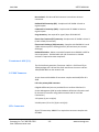
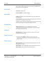
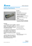
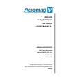
XMC-6280 10-Gigabit Ethernet XMC Module USER’S MANUAL ACROMAG INCORPORATED 30765 South Wixom Road Wixom, MI 48393-2417 U.S.A. Tel: (248) 624-1541 Fax: (248) 624-9234 Copyright 2014, Acromag, Inc., Printed in the USA. Data and specifications are subject to change without notice. 8501-001C XMC-6280 USER’S MANUAL Table of Contents 1.0 GENERAL INFORMATION.............................................................................................. 4 Ordering Information ...........................................................................................................5 Key Features ........................................................................................................................5 Applications.........................................................................................................................5 Hardware Requirements ......................................................................................................6 Software Requirements .......................................................................................................6 MAC Addresses ....................................................................................................................6 2.0 PREPARATION FOR USE ............................................................................................... 7 Unpacking and Inspecting ....................................................................................................7 Card Cage Considerations ....................................................................................................7 Board Installation......................................................................................................................................... 7 P15 Primary XMC Connector ....................................................................................................................... 8 SFP+ Module Connector .............................................................................................................................. 8 Non-Isolation Considerations ...............................................................................................8 3.0 SOFTWARE/DRIVER INFORMATION ........................................................................ 9 Software/Driver Download from Linux Source Tarball ..........................................................9 Software/Driver Download for Windows Operating Systems .............................................. 11 4.0 THEORY OF OPERATION ........................................................................................... 13 PCIE INTERFACE LOGIC ....................................................................................................... 14 SFP+ Module Connectors ................................................................................................... 14 DDR3 ................................................................................................................................. 14 Clock Generation ............................................................................................................... 14 Serial EEPROM ................................................................................................................... 14 Acromag, Inc. Tel: 248-295-0310 http://www.acromag.com -1- -1- www.acromag.com XMC-6280 USER’S MANUAL Serial Flash ........................................................................................................................ 15 Temperature Sensor .......................................................................................................... 15 Power System Devices ....................................................................................................... 15 5.0 SERVICE AND REPAIR ................................................................................................. 17 Service and Repair Assistance ............................................................................................ 17 Preliminary Service Procedure ........................................................................................... 17 Where to Get Help ............................................................................................................. 17 6.0 SPECIFICATIONS ........................................................................................................... 18 PHYSICAL .................................................................................................................................................... 18 POWER REQUIREMENTS ............................................................................................................................ 18 ENVIRONMENTAL ...................................................................................................................................... 18 Terminator 4 ASIC (U1) .............................................................................................................................. 19 P15 XMC Connector ................................................................................................................................... 19 SFP+ Connectors ........................................................................................................................................ 19 Board Crystal.............................................................................................................................................. 20 DDR3 Memory ........................................................................................................................................... 20 256Kb EEPROM .......................................................................................................................................... 20 32Mb Flash ................................................................................................................................................ 20 Temperature Sensor .................................................................................................................................. 20 PCIe Bus Interface ...................................................................................................................................... 20 XMC-6280 Block Diagram ................................................................................................... 21 Certificate of Volatility ....................................................................................................... 22 Acromag, Inc. Tel: 248-295-0310 http://www.acromag.com -2- -2- www.acromag.com XMC-6280 USER’S MANUAL All trademarks are the property of their respective owners. IMPORTANT SAFETY CONSIDERATIONS You must consider the possible negative effects of power, wiring, component, sensor, or software failure in the design of any type of control or monitoring system. This is very important where property loss or human life is involved. It is important that you perform satisfactory overall system design and it is agreed between you and Acromag, that this is your responsibility. The information of this manual may change without notice. Acromag makes no warranty of any kind with regard to this material, including, but not limited to, the implied warranties of merchantability and fitness for a particular purpose. Further, Acromag assumes no responsibility for any errors that may appear in this manual and makes no commitment to update, or keep current, the information contained in this manual. No part of this manual may be copied or reproduced in any form without the prior written consent of Acromag, Inc. Acromag, Inc. Tel: 248-295-0310 http://www.acromag.com -3- -3- www.acromag.com XMC-6280 USER’S MANUAL RELATED PUBLICATIONS The following manuals and part specifications provide the necessary information for in depth understanding of the XMC-6280 board. Chelsio T4/T5 Unified Wire for Linux Installation and User’s Guide http://service.chelsio.com Chelsio T4/T5 Unified Wire for Windows Installation and User’s Guide http://service.chelsio.com 1.0 GENERAL INFORMATION The XMC-6280 is a quad port 10 Gigabit Ethernet Unified Wire adapter XMC module, optimized for cloud computing, HPC, virtualization, storage, and other data center applications. The heart of the XMC-6280 is Chelsio’s Terminator 4 (T4) ASIC. The T4 ASIC provides the highest 10GbE performance available and dramatically lowers host-system CPU communications overhead with on-board hardware that off-loads TCP/IP, iSCSI, FCoE and iWARP RDMA processing from its host system. The XMC-6280 frees up host CPU cycles for useful applications. As a result, the system achieves increased bandwidth, lower latency, and lower power. The XMC-6280 is an XMC module with eight high speed serial lanes allocated to the XMC P15 connector. These lanes are used as an 8-lane PCIe Gen 2 interface. Four high speed Ethernet interfaces are routed from the ASIC to four SFP+ (Small Form-factor Pluggable) module connectors. Each SFP+ port is capable of 10Gb/s full-duplex operation for both fiber optic and copper connections. The XMC-6280 has a 256kb EEPROM, 32Mb of serial flash memory, and 5Gb DDR3 SDRAM. The serial flash memory contains the ASIC’s internal microprocessor firmware code. The EEPROM contains hardware and PCIe configuration information. On power up, the ASIC will copy the firmware from the flash into DRAM. The 5Gb of DDR3 will contain the data buffers and connection information to support up to 32K offloaded connections. Acromag, Inc. Tel: 248-295-0310 http://www.acromag.com -4- -4- www.acromag.com XMC-6280 USER’S MANUAL Ordering Information The following table lists the orderable model and its description. XMC-6280-LF is air-cooled with an operating temperature of -20C to +70C. Table 1.1: The XMC-6280 board is only available in a lead free version. MODEL Description XMC-6280-LF Lead Free, RoHS compliant Key Features An XMC-6280 block diagram, found at the end of this manual, illustrates the key features listed below. Terminator 4 ASIC – A high performance purpose-built protocol processor with a single processor data-flow pipelined architecture that delivers up to one million connections and simultaneously supports wire-speed, fully offloaded TCP/IP, UDP, FCoE, iSCSI and iWARP RDMA on a single unified wire. DDR3 SDRAM – Provides 64 Meg x 72-bit DDR3 SDRAM. The SDRAM is linked to the ASIC device for the storage of the ASIC’s internal microprocessor firmware, data buffers and connection information to support up to 32k offloaded connections. P15 High Speed Interface – Eight high speed serial lanes are allocated to the XMC P15 connector. These lanes are used as an 8 lane PCIe Gen 2 interface to the T4 ASIC. SFP+ High Speed Interface – The four high speed serial interfaces are routed from the ASIC to four SFP+ (Small Form-factor Pluggable) module connectors. SFP+ provides a full-duplex 10GbE interface. Data-Center Networking Applications o Scale up servers and network-attached storage (NAS) systems o Link servers in multiple facilities to synchronize data centers o Consolidate local area networks (LAN), storage area networks (SAN) and cluster networks Cloud Computing o Acromag, Inc. Tel: 248-295-0310 http://www.acromag.com Virtualization features to maximize cloud scaling and utilization -5- -5- www.acromag.com XMC-6280 USER’S MANUAL o Runs InfiniBand, Fibre Channel apps unmodified on Ethernet o Cloud ready functional and management features o Quality of Service (QoS) and Traffic management Networked Storage o Enable high performance NAS systems and Ethernet-based IP SANs o Develop shared-storage systems providing both file- and blocklevel services High Performance Computing o Very low latency Ethernet o Increase cluster fabric bandwidth o Deploy Ethernet-only networking for cluster fabric, LAN and SAN Hardware Requirements The XMC-6280 supports architectures with PCIe (x4, x8) gen 2 slots. Note that running a 10Gb adapter on a PCIe x4 slot is not recommended as performance will be significantly reduced by the limitations of PCIe. PCIe Gen 2 is also backwards compatible with Gen 1; however, the use of Gen 1 will also result in significantly reduced performance. Software Requirements Supported operating systems and functions vary by driver release. The XMC6280 has been developed to run on 64-bit Linux systems as well as 64-bit Windows systems. To know more about the complete list of operating systems supported by each driver, please refer to the driver’s README information available from Chelsio’s website at http://service.chelsio.com. MAC Addresses A MAC ID has been assigned to each of the four SFP+ ports on the XMC-6280. The base address has been listed on a label on the bottom side of the board. The following MAC addresses are assigned in increments of 8. For example, if the base MAC ID is 00:01:C3:00:7F:5A, the following MAC IDs are 00:01:C3:00:7F:62, 00:01:C3:00:7F:6A and 00:01:C3:00:7F:72. Acromag, Inc. Tel: 248-295-0310 http://www.acromag.com -6- -6- www.acromag.com XMC-6280 USER’S MANUAL 2.0 PREPARATION FOR USE Unpacking and Inspecting Upon receipt of this product, inspect the shipping carton for evidence of mishandling during transit. If the shipping carton is badly damaged or water stained, request that the carrier's agent be present when the carton is opened. If the carrier's agent is absent when the carton is opened and the contents of the carton are damaged, keep the carton and packing material for the agent's inspection. WARNING: This board utilizes static sensitive components and should only be handled at a static-safe workstation. For repairs to a product damaged in shipment, refer to the Acromag Service Policy to obtain return instructions. It is suggested that salvageable shipping cartons and packing material be saved for future use in the event the product must be shipped. This board is physically protected with packing material and electrically protected with an anti-static bag during shipment. However, it is recommended that the board be visually inspected for evidence of mishandling prior to applying power. Card Cage Considerations Refer to the specifications section for loading and power requirements. Be sure that the system power supplies are able to accommodate the power requirements of the system boards, plus the installed Acromag board, within the voltage tolerances specified. In an air cooled assembly, adequate air circulation must be provided to prevent a temperature rise above the maximum operating temperature and to prolong the life of the electronics. If the installation is in an industrial environment and the board is exposed to environmental air, careful consideration should be given to air-filtering. In a conduction cooled assembly, adequate thermo conduction must be provided to prevent a temperature rise above the maximum operating temperature. Board Installation Remove power from the system before installing board, cables, termination panels, and field wiring. Acromag, Inc. Tel: 248-295-0310 http://www.acromag.com -7- -7- www.acromag.com XMC-6280 USER’S MANUAL P15 Primary XMC Connector The P15 primary XMC connector connects directly to the T4 ASIC via eight lanes of Gen 2 PCI Express. The connector pin out, complies with the ANSI/VITA 42.3-2006 pin definitions. Note that the XMC-6280 does not support wakeup functionality and does not have a 3.3V aux line. This XMC connector is a 114-pin Samtec ASP-103614-05 connector. The connector complies with the ANSI/VITA 42.3-2006. SFP+ Module Connector Table 2.1: Board Front SFP+ Module Contact definition. Pin Symbol Pin Description 1 2 3 4 5 6 7 8 9 10 11 12 13 14 15 16 17 18 19 20 VeeT Tx_Fault Tx_Disable SDA SCL Mod_ABS RS0 Rx_LOS VeeR VeeR VeeR RDRD+ VeeR VccR VccT VeeT TD+ TDVeeT Module Transmitter Ground Module Transmitter Fault Transmitter Disable 2-wire Serial Interface Data Line 2-wire Serial Interface Clock Module Absent Rate Select Receive Loss of Signal Indication Module Receiver Ground Module Receiver Ground Module Receiver Ground Receiver Inverted Data Output Receiver Non-Inverted Data Output Module Receiver Ground Module Receiver 3.3 V Supply Module Transmitter 3.3 V Supply Module Transmitter Ground Transmitter Non-Inverted Data Input Transmitter Inverted Data Input Module Transmitter Ground Non-Isolation Considerations The board is non-isolated, since there is electrical continuity between the logic and field I/O grounds. As such, the field I/O connections are not isolated from the system. Care should be taken in designing installations without isolation to avoid noise pickup and ground loops caused by multiple ground connections. Acromag, Inc. Tel: 248-295-0310 http://www.acromag.com -8- -8- www.acromag.com XMC-6280 USER’S MANUAL 3.0 SOFTWARE/DRIVER INFORMATION Software/Driver Download from Linux Source Tarball 1. Go to http://service.chelsio.com and search the downloads as shown below. 2. In the SEARCH RESULTS choose the source tarball and click Download. Acromag, Inc. Tel: 248-295-0310 http://www.acromag.com -9- -9- www.acromag.com XMC-6280 USER’S MANUAL 3. Read and accept the Chelsio End User License Agreement. 4. Download the Chelsio support documentation including the README, Release Notes and User Guide. Refer to the User Guide for information on how to properly install and use the Chelsio drivers. Acromag, Inc. Tel: 248-295-0310 http://www.acromag.com - 10 - - 10 - www.acromag.com XMC-6280 USER’S MANUAL Software/Driver Download for Windows Operating Systems 1. Go to http://service.chelsio.com/downloads/Microsoft/ to download the latest Windows Unified Wire driver. Refer to the README file for information on supported operating systems and functionality. 2. View the EULA, then click on Accept EULA & Download to download the .exe file. Acromag, Inc. Tel: 248-295-0310 http://www.acromag.com - 11 - - 11 - www.acromag.com XMC-6280 USER’S MANUAL 3. Run the ChelsioUwire-x.x.x.xx.exe installer application. Refer to the User Guide for information on how to properly install and use the Chelsio drivers. Acromag, Inc. Tel: 248-295-0310 http://www.acromag.com - 12 - - 12 - www.acromag.com XMC-6280 USER’S MANUAL 4.0 THEORY OF OPERATION This section contains information regarding the design of the board. A description of the basic functionality of the circuitry used on the board is also provided. Refer to the XMC-6280 Block Diagram, shown below, as you review this material. Figure 4.1: XMC-6280 Block Diagram XMC PCIe to 4 FIBER 10 GBPS Ethernet DDR III 1600 64Meg X 16 DDRIII x 5 64 + 8 @ 1600 MB/s SERIAL EEPROM SROM 50MHz XTAL CLK TEMP SENSOR SFP+ 10GBPS Ethernet XFI SFP+ 10GBPS Ethernet XFI SFP+ 10GBPS Ethernet XFI SFP+ 10GBPS Ethernet XFI CARRIER BOARD SFLASH CHELSIO T4 ASIC 675 pin FCBGA SERIAL FLASH Thermal GPIO MDIO DC/DC @ 1.0, 1.2, 1.5, 2.5 & 3.3 volts PWR I2C PCIE 2.0 x8 I2C SMB P15 Acromag, Inc. Tel: 248-295-0310 http://www.acromag.com - 13 - - 13 - www.acromag.com XMC-6280 USER’S MANUAL PCIE INTERFACE LOGIC The XMC-6280 host interface is through PCI Express 2.0 which provides a 5Gbps interface to the carrier/CPU board. The PCIe interface supports 8 physical functions (PF). SR-IOV is supported on 4 PF with 128 virtual functions (VF). It supports x1, x2, x4 and x8 link widths. Maximum payload sizes and memory read request sizes of 128B to 2KB are supported, with up to 128 outstanding PCIe reads. SFP+ Module Connectors The board contains four small form-factor pluggable plus (SFP+) connectors and cage assemblies that accept SFP+ modules as well as SFP modules. The SFP+ interfaces are wired directly to the T4 ASICs integrated full-duplex Ethernet MACs. The appropriate SFP rate will be configured automatically by the T4 firmware. Firmware will also be in control of the other SFP signals including Tx_Fault, Tx_Disable, Rx_LOS and Mod_ABS. DDR3 There is a 64 Meg x 72-bit of DDR3 memory onboard for the purpose of storing connection states and buffers for up to 32K offloaded connections. Five DDR3 memory devices are used to form a 72-bit data bus. Each of the devices are 64 Meg x 16 bit (1Gb) in size. Clock Generation There is one onboard 50MHz XTAL providing the core clock to the T4 ASIC. This XTAL is all that is needed in order for the ASIC to internally produce the necessary clocks needed for operation. Serial EEPROM There is a 256Kb Atmel SPI Serial EEPROM which contains all the hardware configuration including things like pll multipliers and PCIe information. It also contains information on how to configure the firmware for the T4 ASIC including things like how to set up the DDR3 and the number of ports available on the card. Acromag, Inc. Tel: 248-295-0310 http://www.acromag.com - 14 - - 14 - www.acromag.com XMC-6280 USER’S MANUAL This Serial EEPROM is not intended to be reprogrammed by the customer, and doing so could cause a device failure. Serial Flash The 32 Mb serial flash contains all the ASIC’s internal microprocessor firmware code. Once the ASIC and microprocessor boots itself, the EEPROM is read first to get configuration information. Then the ASIC copies the firmware from the flash to DDR3 memory and runs everything from there. This Serial EEPROM is not intended to be reprogrammed by the customer, and doing so could cause a failure in the device. The driver will auto-load the firmware if an update is required. The kernel must be configured to enable userspace firmware loading support: Device Drivers Generic Driver Options Userspace firmware loading support Temperature Sensor A Texas Instruments TMP421 temperature sensor is connected to the thermal pins of the Terminator 4 ASIC to monitor the junction temperature of the ASIC and also the local temperature of the temperature senor. The ASIC has been designed to shut down at junction temperatures above 115 degrees Celsius. This is in an attempt to save the chip from being damaged and is not a guarantee that it will not be damaged. Power System Devices The power to the XMC-6280 is taken from the XMC P15 connector VPWR_5/12 pins. The VPWR_5/12 power is the V in voltage to the three LTM4602 devices U16, U17 and U18 and also to the LTM4601 devices U19 and U21. The LTM4602 devices output +2.5V, +1.5V and +1.2V while the LTM4601 devices output +1.0V. The +1.5V supply is input to the TPS51200 device U15 to output +0.75V for DDR3 termination. Acromag, Inc. Tel: 248-295-0310 http://www.acromag.com - 15 - - 15 - www.acromag.com XMC-6280 USER’S MANUAL Figure 4.2: Power Distribution Device Figure 4.3: Power System LTM4602 Reference Designator U17 LTM4602 U16 TPS51200 U15 LTM4602 LTM4601 LTM4601 U18 U19 U21 Acromag, Inc. Tel: 248-295-0310 http://www.acromag.com - 16 - Description ASIC, PCIe, Ethernet ASIC, DDR3, PCIe, Ethernet DDR3 Termination ASIC, Ethernet ASIC, PCIe, ASIC, PCIe - 16 - Power Rail Name P2_5V Power Rail Current 6.0A P1_5V 6.0A DDR3_VTT +/-2A P1_2V P1_0V P1_0V 6.0A 12A 12A www.acromag.com XMC-6280 USER’S MANUAL 5.0 SERVICE AND REPAIR Surface-Mounted Technology (SMT) boards are generally difficult to repair. It is highly recommended that a non-functioning board be returned to Acromag for repair. The board can be easily damaged unless special SMT repair and service tools are used. Further, Acromag has automated test equipment that thoroughly checks the performance of each board. When a board is first produced and when any repair is made, it is tested before shipment. Service and Repair Assistance Please refer to Acromag's Service Policy Bulletin or contact Acromag for complete details on how to obtain parts and repair. Preliminary Service Procedure CAUTION: POWER MUST BE TURNED OFF BEFORE REMOVING OR INSERTING BOARDS Before beginning repair, be sure that all of the procedures in the "Preparation for Use" section have been followed. Also, refer to the documentation of your board to verify that it is correctly configured. Replacement of the board with one that is known to work correctly is a good technique to isolate a faulty board. Where to Get Help If you continue to have problems, your next step should be to visit the Acromag worldwide web site at http://www.acromag.com. Our web site contains the most up-to-date product and software information. Acromag’s application engineers can also be contacted directly for technical assistance via email, telephone, or FAX through the contact information listed at the bottom of this page. When needed, complete repair services are also available. Acromag, Inc. Tel: 248-295-0310 http://www.acromag.com - 17 - - 17 - www.acromag.com XMC-6280 USER’S MANUAL 6.0 SPECIFICATIONS PHYSICAL Height 13.5 mm (0.531 in) Stacking Height 10.0 mm (0.394 in) Depth 149.0 mm (5.866 in) Width 74.0 mm (2.913 in) Board Thickness 1.57 mm (0.062 in) Unit Weight: 4.9144oz (139.32g) POWER REQUIREMENTS Power will vary dependent on the application. 3.3 VDC (5%) Typical 50 mA Max. 100 mA +12/5 VDC (5%) Typical 1 A Max. 1.5 A -12 VDC (5%) 0mA Current Rating (available for the T4 ASIC) On Board 1.0V Power to T4 ASIC 12A typical 1.0V (5%) 24A maximum ENVIRONMENTAL Operating Temperature Operating Temperature Model -20C to 70C XMC-6280-LF Relative Humidity: 5-95% Non-Condensing. Storage Temperature: -55C to 100C. Acromag, Inc. Tel: 248-295-0310 http://www.acromag.com - 18 - - 18 - www.acromag.com XMC-6280 USER’S MANUAL Non-Isolated: PCIe bus and field commons have a direct electrical connection. Radiated Field Immunity (RFI): Complies with IEC 61000-4-3 with no register upsets. Conducted R F Immunity (CRFI): Complies with IEC 61000-4-6 with no register upsets. Surge Immunity: Not required for signal I/O per IEC 61000-4-5. Electric Fast Transient (EFT) Immunity: Complies with IEC 61000-4-4 Level 3 (1.0KV at field I/O terminals). Electrostatic Discharge (ESD) Immunity: Complies with EN61000-4-2 Level 3 (8KV enclosure port air discharge) Level 2 (4KV enclosure port contact discharge). Radiated Emissions: Meets or exceeds European Norm 61000-6-3:2007 for class A equipment. Shielded cable with I/O connections in shielded enclosure is required to meet compliance. Terminator 4 ASIC (U1) The Chelsio fourth generation Terminator 4 ASIC is a 27x27mm 675-pin FCBGA package with a 8-lane PCIe Gen2 interface to the server and four 1GbE/10GbE MACs on the network side. P15 XMC Connector 114 pin Samtec ASP-103614-05 connector complies with ANSI/VITA 42.32006 P15 is the primary XMC connector 8 Gigabit differential pairs are provided for use as 8 lane PCIe Gen 2.0. System Management (XMC provides hardware definition information read by the external controller using IPMI commands and I2C serial bus transactions.) 3.3V power (4 pins at 1A/pin) Variable power (5V or 12V) (8 pins at 1A/pin) SFP+ Connectors 20 pin TE Connectivity 1888247-1 or equivalent connector complies with SFF-8083 Acromag, Inc. Tel: 248-295-0310 http://www.acromag.com - 19 - - 19 - www.acromag.com XMC-6280 USER’S MANUAL SFP+ transceiver signals routed directly to the T4 ASIC are capable of SFP+ maximum data rate of 10 Gigabit/sec. Board Crystal Board Crystal: 50MHz (U22) Frequency Stability: ± 0.00500% or 50ppm DDR3 Memory 64 Meg x 16-bit Micron Device MT41J64M16JT-125:G uses a double data rate architecture. Five MT41J64M16JT-125:G memory devices (U8, U9, U10, U11 and U14) are used to form a 72-bit data bus to the T4 ASIC. The DDR3 is used to store the T4 microprocessor firmware and also for data buffers and connection information when offload is enabled. 256Kb EEPROM 256Kb (32,768 x 8) Atmel SPI Serial EEPROM contains hardware configuration and PCIe configuration information. It also contains the T4 ASIC firmware configuration data. 32Mb Flash 32Mb (4Mb x 8) Micron M25P32 Serial Flash contains the T4’s internal microprocessor firmware code. Temperature Sensor A Texas Instruments TMP421 is supplied as a way to monitor the temperature of the ASIC and is connected to the thermal pins of the Chelsio T4 ASIC. PCIe Bus Interface XMC Compatibility: Conforms to PCI Express Base Specification v2.0, and XMC Specification, P1386.1 ANSI/VITA 42.0: Complies with XMC module mechanicals and connectors ANSI/VITA 42.3: XMC module with PCI Express Interface Acromag, Inc. Tel: 248-295-0310 http://www.acromag.com - 20 - - 20 - www.acromag.com XMC-6280 USER’S MANUAL XMC-6280 Block Diagram XMC PCIe to 4 FIBER 10 GBPS Ethernet DDR III 1600 64Meg X 16 DDRIII x 5 64 + 8 @ 1600 MB/s SERIAL EEPROM Thermal SROM 50MHz XTAL CLK SFP+ 10GBPS Ethernet XFI SFP+ 10GBPS Ethernet XFI SFP+ 10GBPS Ethernet XFI SFP+ 10GBPS Ethernet XFI CARRIER BOARD SFLASH CHELSIO T4 ASIC 675 pin FCBGA SERIAL FLASH TEMP SENSOR GPIO MDIO DC/DC @ 1.0, 1.2, 1.5, 2.5 & 3.3 volts PWR I2C PCIE 2.0 x8 I2C SMB P15 Figure 1 XMC-6280 Block Diagram Acromag, Inc. Tel: 248-295-0310 http://www.acromag.com - 21 - - 21 - www.acromag.com XMC-6280 USER’S MANUAL Certificate of Volatility Certificate of Volatility Acromag Model Manufacturer: XMC-6280-LF Acromag, Inc. 30765 Wixom Rd Wixom, MI 48393 Volatile Memory Does this product contain Volatile memory (i.e. Memory of whose contents are lost when power is removed) ■ Yes □ No Type (SRAM, SDRAM, etc.) Size: User Modifiable Function: Process to Sanitize: SDRAM 64 Meg x ■ Yes Power Down 72-bit □ No Data storage for ASIC Non-Volatile Memory Does this product contain Non-Volatile memory (i.e. Memory of whose contents is retained when power is removed) ■ Yes □ No Type(EEPROM, Flash, etc.) Size: User Modifiable Function: Process to Sanitize: Flash 32Mbit □ Yes Storage of ASIC Firmware Not applicable ■ No Type(EEPROM, Flash, etc.) Size: User Modifiable Function: Process to Sanitize: EEPROM 246Kbit ■ Yes Storage of PCIe, hardware and ASIC configuration data Clear EEPROM memory by writing zeros to all sectors of the EEPROM □ No Acromag Representative Name: Title: Email: Office Phone: Office Fax: Joseph Primeau Dir. of Sales and Marketing [email protected] 248-295-0823 248-624-9234 Acromag, Inc. Tel: 248-295-0310 http://www.acromag.com - 22 - - 22 - www.acromag.com XMC-6280 USER’S MANUAL Revision History Release Date Version EGR/DOC 5-DEC-13 A EZ/EZ Initial Acromag release. 1-MAY-14 B EZ/EZ Added power requirements, Theory of Operation, temperature sensor and MAC address information. Revised Environmental conditions involving immunities and emissions. 2-Oct-15 C CAB/MJO Acromag, Inc. Tel: 248-295-0310 http://www.acromag.com Description of Revision Remove Leaded Option for RoHS compliance. - 23 - - 23 - www.acromag.com