1
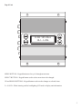
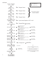
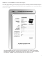
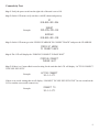
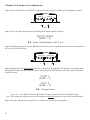
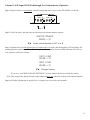
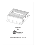
iLink LCD
by
Nel-Tech Labs, Inc.
Installation & User Manual
Index:
Introduction ........................................................................................................................3
iLink Layout Summary..................................................................................................... 4 - 5
LCD Layout Summary ......................................................................................................6
Web Browser .....................................................................................................................7
Installation ....................................................................................................................... 8
Connectivity Test/Volume Adjustments................................................................................
9 - 11
Troubleshooting ................................................................................................................ 12
Warranty & FCC ....................................................................................................................
13
Introduction:
The iLink LCD is an Internet downloadable messaging system utilizing state-of-the-art MPEG compression to achieve
truly stunning near-CD quality audio storage and playback. All unit management and audio downloads are accomplished by
your dealer using a special controller software suite. When an update is needed your dealer connects to the iLink via your
high-speed Internet connection and digitally transfers the MP3 audio files and configuration settings you need. Changes can
be initiated on demand, scheduled from minutes to weeks, or the iLink can be instructed to connect automatically and load
new audio.
Unpacking and Inspection:
Before you begin installation, unpack and verify you have all the correct parts.
(1) iLink LCD
(1) 12VDC @ 500mA power supply
(1) Ethernet cable
(1) RCA to RCA cable
(1) RCA to 3.5mm adapter
(2) Wall mount screws
(1) Instruction manual
If you are missing any of these parts STOP and call your dealer.
3
iLink Layout Summary:
Front of Unit
12VDC
500mA
+
LAN
POWER
ON
(1)
OFF
(0)
12VDC - This is where the supplied 12VDC @ 500mA power pack is connected.
POWER - Use this switch to turn the unit ON and OFF.
LAN - This jack connects to the local Ethernet that allows the iLink connectivity to the Internet. The jack also has
two built in LEDs that report back network activity and speed status.
Rear of Unit
MADE IN USA
CHANNEL A
IN
OUT
█ 600Ω
▄ 8Ω
CHANNEL B
IN
OUT
█ 600Ω
▄ 8Ω
CHANNEL A or B (IN) - This signal level jack allows an external BGM (Background Music) source to be fed
through the iLink unit.
CHANNEL A or B (OUT) - This jack connects to a phone systems MOH input or a PA amplifier.
8Ω or 600Ω - This switch changes the output impedance of the CHANNEL A or B (OUT) jack.
4
Top of Unit
iLink v07.00.a
10.1.1.206
MENU BUTTON - Keypad button used to cycle through menu items.
SELECT BUTTON - Keypad button used to select menu item to be changed.
UP and DOWN BUTTONS - Keypad buttons used to make changes to selected items.
2 x 16 LCD - White lettering on blue backlighting LCD used to display unit information.
5
LCD Menu
= Menu Button Push
iLink v07.00.a
10.1.1.206
}
Output A
Volume = XX
qp
Changes Volume
Output B
Volume = XX
qp
Changes Volume
Input A BGM
Volume = XX
qp
Changes Volume
Input B BGM
Volume = XX
qp
Changes Volume
Monitor Speaker
Source = XX
qp
Cycles Internal Speaker to OFF, A or B
IP Mode
DHCP or Static
qp
Changes Mode
IP
XXX.XXX.XXX.XXX
Subnet
XXX.XXX.XXX.XXX
Gateway
XXX.XXX.XXX.XXX
Connect-Back IP1
XXX.XXX.XXX.XXX
“Select” flashes first octet
qp Changes digit
“Select” confirms and moves to next octet
“Select” flashes first octet
qp Changes digit
“Select” confirms and moves to next octet
“Select” flashes first octet
qp Changes digit
“Select” confirms and moves to next octet
“Select” flashes first octet
qp Changes digit
“Select” confirms and moves to next octet
Connect-Back Prt
XXXX
PRESS UP ARROW
TO CONNECT-BACK
Format
& Reboot
Firmware Version
vXX.XX.X
MAC ADDRESSS
000000000000
qp Changes digit
“Select” confirms and moves to next octet
qp
Changes Port
“Up to Confirm”
Locked if local volume
control is disabled
“Up to Confirm”
“Down to Cancel”
“Select” flashes first octet
Connect-Back IP2
XXX.XXX.XXX.XXX
6
= Select Button Push
“Up to Confirm”
“Down to Cancel”
“Up to Confirm”
“Down to Cancel”
“Up to Confirm”
“Down to Cancel”
“Up to Confirm”
“Down to Cancel”
“Up to Confirm”
“Down to Cancel”
“Up to Confirm”
“Down to Cancel”
Note:
Changes to IP Settings only available in STATIC
MODE
“Up to Confirm”
“Down to Cancel”
If MAIN MENU is idle for more than 30 seconds the
LCD reverts back to MAIN SCREEN
If SUB MENU is idle for more than 300 seconds the
LCD reverts back to MAIN SCREEN and CANCELS
any current changes.
Web Browser (Feature on firmware version 07.09X or higher)
The iLink LCD has a built-in password protected web browser that will display the units serial number, firmware
version and MAC address. This browser will also allow the units communication mode, connect-back address
and port to be changed.
When changing Mode either DHCP or STATIC must be typed in the “New Settings” column. When
changing to STATIC mode the IP, Subnet and Gateway must all be entered or the settings will not take
when submitted. The Status will indicate if the settings have been updated to the unit.
7
Installation :
Step 1: Wall or shelf mount the unit. Rubber feet and screws are supplied in the accessory kit.
Step 2: Verify the power switch on the right side of the unit is set to OFF. Attach the included power pack to a
wall or power strip receptacle, then attach the other end to the jack on the right side of the unit labeled 12VDC.
Step 3: If connecting unit to an amplifier make sure it is turned OFF for this part of the installation.
Step 4: Connect a RCA cable (supplied in the accessory kit) to the CHANNEL A (OUT) jack on the left side of
the unit. Connect the other end of the RCA cable to a phones MOH port, PA amplifier or speaker. For dual output
applications follow the same procedure for the CHANNEL B (OUT).
Step 5: (Optional) For messaging only applications the existing BGM (Background Music) can be fed through
the iLink. Connect the audio source to the CHANNEL A or B (IN) jack(s) on the left side of the unit. This jack
must only be fed signal level audio - ANY AMPLIFIED AUDIO WILL DAMAGE THE UNIT.
Step 6: Connect an Ethernet cable (supplied in the accessory kit) to the LAN jack on the right side of the unit.
Connect the other end to a 10/100 speed switch or hub.
Wiring Diagram
Left Side
Right Side
MADE IN USA
12VDC
500mA
8
OUT
▄ 8Ω
(Optional)
IN
+
LAN
POWER
ON
(1)
OFF
(0)
To Switch or Hub
█ 600Ω
To MOH or PA
▄ 8Ω
(Optional)
OUT
To MOH or PA
(Optional)
From BGM Source
IN
█ 600Ω
CHANNEL B
From BGM Source
CHANNEL A
Connectivity Test:
Step 1: Verify the power switch on the right side of the unit is set to ON.
Step 2: On the LCD menu verify unit has a valid IP, subnet and gateway.
IP
010.001.001.206
Example:
Subnet
255.255.255.128
Gateway
010.001.001.120
Step 3: On the LCD menu go to the “PRESS UP ARROW TO CONNECT-BACK” and press the UP ARROW.
PRESS UP ARROW
TO CONNECT-BACK
Step 4: The LCD will display the “FORCING CONNECT PLEASE WAIT”
FORCING CONNECT
PLEASE WAIT
Step 5: If there is a Connect-Back record waiting for the unit then the LCD will display “ACTIVE CONNECT
XXX.XXX.XXX.XXX”.
Example:
ACTIVE CONNECT
10.1.1.171
If there is no record waiting then it will display “CONNECT TO XXX.XXX.XXX.XXX” for one second on the
LCD to confirm a successful connectivity.
Example:
CONNECT TO
10.1.1.171
9
Channel A & B Output Level Adjustments:
Step 1: Verify CHANNEL A or B (OUT) is connected to either a phone’s MOH port, PA amplifier or speaker.
MADE IN USA
CHANNEL A
IN
OUT
█ 600Ω
▄ 8Ω
CHANNEL B
IN
OUT
█ 600Ω
▄ 8Ω
and/or
Step 2: Verify the unit is playing audio by listening to the internal monitor speaker.
Monitor Speaker
Source = XX
qp
Cycles Internal Speaker to OFF, A or B
Step 3: Depending upon the device the 8Ω/600Ω switch may need to be pushed to better match the impedance of
the device the iLink is driving.
MADE IN USA
CHANNEL A
IN
OUT
█ 600Ω
▄ 8Ω
CHANNEL B
IN
OUT
█ 600Ω
▄ 8Ω
Step 4: Adjustment of the stored audio output level can be done through the LCD and Menu. Depending upon
the application either call into the phone system and be placed on hold OR listen to the PA systems speakers to
fine tune volume.
Output A
Volume = XX
Output B
Volume = XX
qp
Changes Volume
If you see a “LOCKED VOLUME SETTINGS” message then the dealer has locked this setting.
Note: This setting only adjusts the units audio outputs and does not adjust the volume of the internal speaker!
Step 5: All audio adjustments are applied live so changes are saved to the unit instantly.
10
Channel A & B Input BGM Feedthrough Level Adjustments (Optional):
Step 1: Plug feed from an unamplified external background music source to the CHANNEL A or B (IN)
MADE IN USA
CHANNEL A
IN
█ 600Ω
OUT
▄ 8Ω
CHANNEL B
IN
█ 600Ω
OUT
▄ 8Ω
and/or
Step 2: Verify the unit is playing audio by listening to the internal monitor speaker.
Monitor Speaker
Source = XX
qp
Cycles Internal Speaker to OFF, A or B
Step 3: Adjustment of the background music feedthrough level can be done through the LCD and Menu. Depending upon the application either call into the phone system and be placed on hold OR listen to the PA systems speakers to fine tune volume.
INPUT A BGM
Volume = XX
INPUT B BGM
Volume = XX
qp
Changes Volume
If you see a “LOCKED VOLUME SETTINGS” message then the dealer has locked this setting.
Note: This setting only adjusts the units audio inputs and does not adjust the volume of the internal speaker!
Step 4: All audio adjustments are applied live so changes are saved to the unit instantly.
11
Other LCD Status Messages:
Unit is booting:
Booting...
please wait...
Unit is initializing:
ilink 07.00.a
initializing...
Unit is getting ip address:
ilink 07.00.a
seeking ip...
Dealer is connected to unit:
DIRECT CONNECT
IS ACTIVE
Unit is connected to dealer:
ACTIVE CALLBACK
xxx.xxx.xxx.xxx
Format and reboot in progress :
FACTORY RESET
In PROcESS
Unit is formatting:
iLink 07.00.A
FORMATTING
LAN LED Indicators
MADE IN
THE USA
Yellow
Action
10MB
Not Used
100MB
12
LED
OFF
FLASHING
SOLID
LAN
CHANNEL B
CHANNEL A
IN
OUT
600Ω
8Ω
IN
OUT
600Ω
8Ω
OFF
Green
Action
No Activity
Activity
Link
POWER
LED
OFF
FLASHING
SOLID
ON
Limited Warranty
TERMS: Nel-Tech Labs warrants to the original purchaser (“Buyer”) that the Product sold is free from defects in material and
workmanship at the time of purchase. The warranty period begins at the time of Product’s original purchase by the first end-user. The
warranty applies for five (5) year from the original date of purchase, or as long as the product is owned by the original purchaser,
whichever comes first. Included in the warranty are parts and labor. Buyer must provide written notice to Nel-Tech Labs of any
defective part or conditions within the warranty period. If the defect is not the result of improper use, service, maintenance or
installation, and if the equipment has not been otherwise damaged or modified after shipment, Nel-Tech Labs or its authorized
representative shall either replace or repair the defective Product at Nel-Tech Labs’s option. No credit shall be allowed for work
performed by Buyer or unauthorized parties. Out-of-warranty repairs are invoiced at the current Nel-Tech Labs hourly rate plus the
cost of parts, shipping and handling. In the event that the product serial number is missing or has been tampered with in any way,
the foregoing warranty is void and without effect and Nel-Tech Labs shall have no liability whatsoever on account of defects to such
product.
LIMITATIONS: Except as stated above, there are no warranties, express or implied, that extend beyond the specifications for the
product. Nel-Tech Labs expressly disclaims any warranty, express or implied, that equipment sold hereunder is of merchantable
quality or that it can be used, or is fit for any particular purpose. Buyer purchases and accepts equipment solely on the basis of the
warranty here in above expressed. Under no circumstances shall Nel-Tech Labs be liable by virtue of this warranty or otherwise
for any special indirect, secondary or consequential damages to any person or property arising out of the use or inability to use the
product.
REPAIRING OR REPLACING PRODUCT: Buyer may obtain the repair or replacement of any eligible part or equipment covered
under this warranty through a Nel-Tech Labs dealer only. Buyer is responsible for all shipping and handling charges in connection
with the performance of this warranty. Products returned to Nel-Tech Labs must be securely packaged to prevent damage in transit,
freight prepaid, and insured for replacement value. A return authorization number assigned by Nel-Tech Labs must be clearly marked
on the outside of the shipping container. Proof of purchase must accompany shipment. Items delivered to Nel-Tech Labs without a
return authorization clearly marked on the outside of the shipping container, and/or without proof of purchase is refused.
CONTACT: Please contact Nel-Tech Labs at the address and phone number below to receive a return authorization number and to
arrange for the repair or replacement of a flawed part covered by this warranty. Please indicate the Product’s serial number in all
correspondence or a RMA authorization number in the absence of a serial number. Nel-Tech Labs, 4 Ash Street Extension, Derry,
NH 03038, Phone: 1.603.425.1096.
COPYRIGHT NOTICE: Unauthorized or unlicensed use of copyrighted audio content is illegal and Nel-Tech Labs, Inc. takes no
responsibility for such action by the user of this equipment.
FCC Part 15 : This equipment has been tested and found to comply within the limits for a Class A digital device, pursuant to Part
15 of the FCC rules. These limits are designed to provide reasonable protection against harmful interference when the equipment is
operated in a commercial environment. This equipment generates, uses and can radiate radio frequency energy and, if not installed
and used in accordance with the instruction manual, may cause harmful interference to radio communications. Operation of the
equipment in a residential area is likely to cause harmful interference in which case the user will be required to correct interference at
his own expense. In order to maintain compliance with FCC regulations shielded cables must be used with this equipment. Operation
with non-approved equipment or unshielded cables is likely to result in interference to radio & television reception.
Changes or modifications not expressly approved by Nel-Tech Labs could void the users’ authority to operate the equipment.
IC ES 003 : This Class A digital apparatus complies with Canadian ICES-003 C et appareil numérique de la classe A est conform e
à la norme NMB-003 du Canada.
CE CONFORMITY : The Nel-Tech Labs iLink conforms with the following standards, in accordance with the EU Safety,
EMC Emissions, & EMC Immunities : EN 60950-1:2001, EN 55022:1998 for Class A, EN 55024:1998 + A1:2001 + A2:2003,
EN 61000-4-2:1995 + A1:1998, EN 61000-4-3:1995, EN 61000-4-4:1995, EN 61000-4-5:1995, EN 61000-4-6:1996, EN
61000-5-11:1994.
13
Nel-Tech Labs, Inc.
4 Ash Street Extension
Derry, NH 03038
1.800.344.4685
www.nel-techlabs.com
ilink_lcd_manual
Rev. B - 09/11
Copyright © 1984 - 2011 by Nel-Tech Labs, Inc.