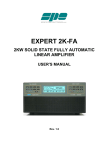
1
MARS-ALE LE/SE
Quick Start Guide
Version 1.02 Beta Released 04-17-06
DRAFT
MARS-ALE
v1.02 BETA
Quick Start Up Guide
POC for this document is
AAR2EY/NJ U.S. Army MARS
[email protected]
[email protected]
http://groups.yahoo.com/group/MARS-ALE/
This MARS-ALE User Guide supersedes all previous edition’s
of this guide. All previous edition’s should be destroyed.
MARS ALE STATION APPROVALS: All U.S. Army MARS members desiring to
operate on ALE NETS must get authorization per the guidelines in Chapter 8, Section 8-8
of the US Army MARS NET PLAN. Written permission is required for any MARS
station to sound on any Army MARS ALE Network channels. MARS members from
other services are required to get authorization from their respective Chiefs, through their
SMDs.
1
MARS-ALE LE/SE
Quick Start Guide
Version 1.02 Beta Released 04-17-06
WARNING: Stations that have not received direct authority and direction to do so, should NOT be
actively participating in multi-channel Sounding operation on ARMY MARS channels. Contact AAR3BB
for information regarding the current status of full Sounding operation for U.S. Army MARS members or
the use of single channel Beacon Sounding used by Army MARS NCS stations for NET pre-check-in.
WARNING: The MARS-ALE tool is NOT authorized for use on the Amateur Bands.
WARNING: Installing this BETA or any release of MARS-ALE on your PC to an existing directory
where you have a MARS-ALE installation WILL wipe out your existing ALE.DAT file! It will NOT harm
your LICENSE.DAT file however. You should always keep a backup of your ALE.DAT and license.dat
files as they can become corrupted should the program crash at the wrong time when the file is being
accessed. In addition a .QRG file should be created when GROUP/Channel settings are changed and to
periodically create a file with all recent NET, OWN and OTHER address changes.
WARNING: Beginning with MARS-ALE SE B001A8g4, the tool now supports direct control of certain
types of external and internal Automatic Antenna Tuner (ATU) and Antenna Switch make/models where
there use is selected by as combination of configuration choices on the MIL-STD-188-141 Options dialog
and the Channel Add/Modify dialogs and come into on a channel by channel basis. The operator must take
the time to read and understand the documentation associated with these advanced ATU and antenna
selection features to properly configure for their stations equipments.
WARNING: The ALE.DAT file structure has changed with the release of this BETA. As such you must
first run your existing installation of MARS-ALE and use Fill > DUMP to create a .QRG file with your
existing configuration of GROUP/Channels and Addresses which will later be loaded into the new beta
release to populate your new ALE.DAT file. You will then need to use the configuration dialogs to make
your station specific settings such as radio make/model selected, com port etc.
WARNING: If you use any FULL install of MARS-ALE and select a path different than an existing
installed version, it WILL change the path settings for your standard MARS-ALE desktop icons. Thus if
you added the installation to a new sub directory, like MARS-ALE_SE, when you click on the ICON, you
will fire off that build and NOT the previously installed build. Thus make your own icons to the build(s)
that you may want to work with.
NOTE: The difference between MARS-ALE “SE” and MARS-ALE Legacy Edition (LE) is that MARSALE LE version has been tailored to use an 8Khz vs. 48Khz sample clock and all MIL-STD-188-110
modem support has been removed as it requires 48Khz. LE 8Khz will now work on systems all the way
down to Pentium 133Mhz and Windows 98SE and ISA sound devices. A stand alone machine without a
network card or any other non-OS software running, which is dedicated to MARS-ALE will provide the
best results.
2
MARS-ALE LE/SE
Quick Start Guide
Version 1.02 Beta Released 04-17-06
MARS-ALE DO’s and DON’Ts
Do expect to put effort into the MARS-ALE learning curve as this is a sophisticated communications tool.
Do fully read this documentation before attempting to make any use of MARS-ALE.
Do fully read the MARS-ALE “Radio Help User Guide” before attempting to make any use of MARSALE.
Do follow all the directions and recommendations of the MARS-ALE documentation.
Don’t allow your MARS-ALE license.dat file to get out of your safe keeping.
Don’t assume MARS-ALE is “Plug ‘n Play” and that if it doesn’t work as advertised it must be a problem
with the software.
Don’t assume MARS-ALE is just another digital mode program and should work with your current radio
station because you are using a software application that seems to work correctly.
Don’t forget that Automatic Link Establishment and supporting standards and protocols are normally
implemented using very expensive radio equipments which require extensive training to master.
Don't assume a channel is unoccupied, MARS-ALE may not determine if the channel is busy with voice or
data traffic before it transmits. An operator has no indication if two other stations are currently linked.
Don’t assume that all ALE stations are using MARS-ALE, many are using ALE hardware solutions and
only support AMD for messaging.
Don’t use the MOTD feature is you want to allow your station to accept calls from ALE hardware based
user’s and AQC-ALE calls.
Don’t use MARS-ALE on the U.S. Amateur Bands for anything beyond monitoring.
Don’t hesitate to provide the MARS-ALE SDT feedback on the tool and its documentation.
Don’t have any screen saver’s of system hibernate or resources power down while running MARS-ALE.
3
MARS-ALE LE/SE
Quick Start Guide
Version 1.02 Beta Released 04-17-06
TABLE OF CONTENTS
OVERVIEW………………………………………………
ALE FREQUENCY SELECTION………………………..
ALE OPERATIONAL LIMITATIONS…………………..
REFERENCES……………………………………………
INSTALLING THE BETA SOFTARE…………………..
STARTING THE PROGRAM……………..……………..
MARS-ALE CONFIGURATION………………………...
MIL-STD-188-141A OPTIONS MENU………………….
MIL-STD-188-110 OPTIONS MENU……………………
FS-1052 APPENDIX B OPTIONS MENU……………….
SOUND CARD CONFIGURE……………………………
TRACING MENU………………………………………...
CURRENT GROUP SETUP……………………………...
ADD CHANNEL………………………………………….
ALE ADDRESSES………………………………………..
ADD ADDRESSES……………………………………….
PC SOUNDS AND ALE MODEM……………………….
SETTING UP TX AUDIO………………………………...
SETTING UP RX AUDIO………………………………...
TUNE WINDOW………………………………………….
HOW SYNC WORKS……………………………………..
TRACING DETAILS……………………………………...
DATA MODES……………………………………………
RADIO ADJUSTMENTS…………………….…………...
ACCELERATOR KEYS AND FRONT PANEL
CONTROLS ……………………………………………..
QUIET SCANNING/SOUDNING………………………...
ALTERNATE QUICK CALL (ALE)……………………..
4
5
7
7
8
10
11
14
17
34
37
40
42
44
45
47
48
49
50
51
52
53
58
60
64
66
70
72
MARS-ALE LE/SE
Quick Start Guide
Version 1.02 Beta Released 04-17-06
OVERVIEW
This start up document has been updated for the MARS-ALE Standard Edition (SE) and Legacy
Edition (LE) v1.02 BETA version build B001A8g8 and provides a synopsis of information
(Software Configuration, TUNE Display Window, Data Protocol and Modes, PC Sound Device,
Radio Parameters and more) that will found in the other MARS-ALE documentation in detail
regarding the installation, configuration and application of the MARS-ALE tool.
The MARS-ALE v1.02 BETA software provides the following new features which will be
described in detail herein:
•
Developed new 8Khz sample clock Legacy Edition for slower legacy PC systems
•
Alternate Quick Call (AQC) ALE is now enabled for testing having been improved
•
FED-STD-1052 ARQ protocol is now enabled for testing having been improved
•
Developed Quiet Scanning/Sounding (QS/S) to protect radio relays during Scanning
•
Added front panel access to important MIL-STD-188-141 Options parameters (Linked
TWX, Sounding, AQC-ALE, AQC-Burst, TWA and SCLC values)
•
Added Radio 1 Alternate RTS/DTR port for dedicated PTT and MUTE serial port
support
•
Added ATU Tune Words to generate an ATU tuning tone using the ALE AFSK modem
on any PC sound device in the system used as the ALE modem
•
Added ATU Tune Level to control the RF drive when using ATU Tune Words. NOTE:
This feature is currently set to a fixed level regardless of the value entered.
•
Added option for TX Audio Level setting to control RF power output on a channel by
channel basis.
•
Added support for the Official MARS Message program, regardless as to where it is
installed on your system. Help > MARSMSG will launch that tool so that you can use it
to create an EEI or whatever and then paste it into MARS-ALE to send
•
Added support for radio CAT ATU and ANT SW support when radio make/models
support such capability. The CAT ATU and ANT SW control is provided on Channel by
Channel basis.
•
Added support for RS-232 based LDG AT200PC external ATU/ANT SW and the
ACOM and LDG DTS-x series of external ANT SW devices on a channel by channel
basis.
5
MARS-ALE LE/SE
Quick Start Guide
Version 1.02 Beta Released 04-17-06
•
Added support for RS-232 serial RTS and DTR lines for external ANT SW selection on a
channel by channel basis where external interface circuitry is provided in support of
antenna switching.
•
Added support for CAT Attenuator support for radios which support such on a channel
by channel basis.
•
Refer the RHUG for all newly added or updated supported transceivers and receivers.
The MARS-ALE v1.02 BETA software provides the following enhanced features which will be
described in detail herein:
•
Improved FSK/PSK modem core to include better performance under all channel
conditions and compensation for sample clock error (very effective for sound devices at
48Khz as the error is a smaller fraction of the sample clock, however at 8khz (LE)
symbol lengths are not 8ms long which causes the sync point to walk) and modem
resetting and the
•
Improved Alternate Quick Call (AQC) ALE
•
Improved FED-STD-1052 ARQ
•
FFT rounding problem has been solved allowing endless 24/7 operation
•
AFSK audio drive is higher during FSK ALE (good news for ICOM transceivers)
•
Support for additional make/model radios, Support for hardware handshaking with
Kenwood radio models, Support added for Storage/Retrieval/Deletion of the last 100
received AMD messages stored in the ALE.DAT database file
•
Tracing functions are now automatically turned off at normal program terminate and
LQA becoming unchecked during program use has been fixed
•
ATU wave file playing while ALE tones sending has been fixed.
•
The problem with the log files not being created/saved on other than drive C: has been
fixed.
•
The Channels > List which only listed 8 GROUPS now lists all 16 GROUPS
•
At program start the OWN/SELF database and the current GROUP and all its Channels
are displayed, which is in response to helping the operator know what OWN/SELF
Addresses are being used and what channels are in the currently active GROUP at a
glance
•
Improved QS/S in for a number of radios and fixed a few general bugs.
•
Fixed all problems with LQA based Individual Calls while Scanning/Sounding.
6
MARS-ALE LE/SE
Quick Start Guide
Version 1.02 Beta Released 04-17-06
•
Improved DTM ARQ and DBM ARQ by fixing problems with state machine timing.
If you only read and follow the directions outlined within this document, you should be able to
start using MARS-ALE immediately after installing the software and placing your license.dat file
into the same directory you installed ALE.EXE and after entering all the needed setup
parameters. However, reading the MARS-ALE “User Manual” and “Radio Help Operator Guide”
is highly recommended for a complete understanding of the tool. Provided as a separate
document with this BETA release is an updated “Appendix A” from the “Radio Help Operator
Guide” which details all radio make/models supported by this BETA.
This guide is designed for the first time user of MARS-ALE, regardless of whether they have any
PC sound device (sound card) digital mode experience or not. Those with PC sound device digital
mode experience must NOT make any assumptions that their existing PC to radio interfacing and
sound levels as configured for the digital modes that they have previously used will work as is
with MARS-ALE. It is STRONGLY recommended that all directions as to how to configure
such parameters for MARS-ALE be followed to obtain the best results as MARS-ALE is not just
another sound card digital mode program.
For information as to how the tool is actually used for sending and receiving messages, please
refer to the MARS-ALE “User Guide”. For information on the details of Radio Control and Radio
interfacing to the PC sound device, please see the MARS-ALE “Radio Help Operator Guide”. For
more in depth technical back ground on ALE and the MARS-ALE please refer to the DRAFT
“MARS-ALE Technical Reference Manual” which is not distributed with the tool but is available
for download from the support web sites.
ALE FREQUENCY SELECTION
The following is directly quoted from “HF-ALE MULTI-SERVICE TACTICS,
TECHNIQUES, AND PROCEDURES FOR THE HIGH FREQUENCY AUTOMATIC
LINK ESTABLISHMENT (HF-ALE) RADIOS, FM 6-02.74, MCRP 3-40.3E, NTTP 602.6, AFTTP(I) 3-2.48, COMDTINST M2000.7, SEPTEMBER 2003” page 21.
3. Frequency Selection
a. For ALE to function properly, frequency selection is important. When selecting
frequencies to use in a network, take into consideration the times of operation and
distances to be communicated, power level used, type of antenna(s) used and so forth.
b. When using the above parameters, a good propagation program should also be used to
determine which frequencies will propagate. Appendix H lists some of the available
propagation software programs and contact information.
c. Consulting with the frequency manager early on in this process may save you a lot of
work, since the manager may already have lists of approved frequencies that can be used
for particular functions in given areas.
ALE OPERATIONAL LIMITATIONS
The following is directly quoted from “HF-ALE MULTI-SERVICE TACTICS,
TECHNIQUES, AND PROCEDURES FOR THE HIGH FREQUENCY AUTOMATIC
7
MARS-ALE LE/SE
Quick Start Guide
Version 1.02 Beta Released 04-17-06
LINK ESTABLISHMENT (HF-ALE) RADIOS, FM 6-02.74, MCRP 3-40.3E, NTTP 602.6, AFTTP(I) 3-2.48, COMDTINST M2000.7, SEPTEMBER 2003” page 21.
“4. Limitations
a. ALE is a tool that automates HF linking and frequency selection. It does not replace a
properly trained HF operator. Knowledge of the specific radio equipment being used,
propagation, antennas, and so forth is still essential to use ALE effectively.
b. ALE will not improve propagation. If poor propagating frequencies are used, ALE will
not make them work better. ALE only works as well as the frequencies you put into it;
therefore, proper frequency management is essential.
c. ALE makes the linking process more automatic, allowing a novice HF user to use the
radio effectively. However, ALE in some cases takes more time than it takes two highly
trained HF operators to establish a link.
d. ALE determines only the best channel to pass traffic and tries to establish a link
between radios. The ALE function, in itself, does not provide data capability other than a
simple automatic message display (AMD) in the ALE header signal or other equipment
specific features.
e. Depending on the specific equipment used, ALE may not determine if the channel is
busy with voice or data traffic before it transmits. An operator has no indication if two
other stations are currently linked.”
REFERENCES
MARS-ALE SE v1.01 User Manual, 10 October 2005
MARS-ALE SE v1.02, Radio Operators Help Guide Appendix A, 23 March 2006
MARS-ALE Application Note, Training and Operation of the LDG Electronics AT-200PC
for use with MARS-ALE, Version 1.01, 24 March 2006
MARS-ALE Application Note, RS-232 Computer Control Interface for LDG Electronics DTS4/DTS-6 Desktop Coaxial Switches, Version 1.01, 23 February 2006
ARMY MARS NET PLAN, 1 DECEMBER 2005
U.S. ARMY MARS DIGITAL OPERATIONS AND TRAINING GUIDE, SEPTEMBER 2005
FED-STD-1045A, 18 OCTOBER 1993
MIL-STD-188-141A and Appendix A
MIL-STD-188-141B Appendix A, AQC-ALE, 31 AUGUST 2001
MIL-STD-188-110A
8
MARS-ALE LE/SE
Quick Start Guide
Version 1.02 Beta Released 04-17-06
FED-STD-1052 Appendix B, Data Link Protocol
HF-ALE MULTI-SERVICE TACTICS, TECHNIQUES, AND PROCEDURES FOR THE HIGH
FREQUENCYAUTOMATIC LINK ESTABLISHMENT (HF-ALE) RADIOS FM 6-02.74,
MCRP 3-40.3E, NTTP 6-02.6, AFTTP(I) 3-2.48, COMDTINST M2000.7
FTSC Test Plan for Interoperability and Performance of HF ALE Radios
NIST Special Database 17, NIST Automatic Link Establishment (ALE) Tones per FED-STD1045A and 1046/1
NIST Special Database 21, NIST Automatic Link Establishment (ALE) Degraded Tones Per FedSTD-1045
JITC MIL-STD-188-141B CONFORMANCE TEST PROCEDURES, November 2003
JITC MIL-STD-188-110B CONFORMANCE TEST PROCEDURES, July 2004
NOTE: Most of the above references can be found in many places on the internet, most
can be found at www.n2ckh.com/MARS_ALE_FORUM
9
MARS-ALE LE/SE
Quick Start Guide
Version 1.02 Beta Released 04-17-06
INSTALLING THE BETA SOFTWARE
The process for installation of the BETA can be one of two methods detailed below, do NOT just
drop the BETA version into your pre-existing MARS-ALE directory as the BETA release has a
new ALE.DAT file structure, thus your pre-existing ALE.DAT file will be considered corrupt and
will be over written if present by the BETA version when started.
METHOD 1.
NOTE: If you have NOT previously installed a earlier version of v1.02 Beta, then you MUST
run the existing version of MARS-ALE v1.01 before installing the BETA version if you are
going to use this method.
If you have never installed MARS-ALE in the past or you prefer to automate the process,
make a full installation of MARS-ALE SE v1.01 to a directory specific for use with this beta
and then copy all of the files distributed with the beta to the same sub directory.
Next, if you have previously installed MARS-ALE, run that version of the tool and check that
you have the proper Army ALE channels configured with respect to the 1 December 2005
Net Plan ALE channel changes and use Fill > Dump to create a .QRG file with your
GROUP/Channel information and Addresses. Then exit the program and start the BETA
following the directions herein to include importing the .QRG file just created and making the
needed changes to your configuration settings and exit the program normally to save the
changes to the tools ALE.DAT database file.
Otherwise using the provided MARS_SHARES.QRG supplied with the beta, make sure to
edit all instances of the OWN example Address to read your primary ALE Address follow the
directions herein to include importing the MARS_SHARES.QRG file making the needed
changes to your configuration settings and exit the program normally to save the changes to
the tools ALE.DAT database file.
METHOD 2.
The second option is to manually create a new subdirectory for the beta and copy over all of
your existing files from your installed version of MARS-ALE. Then copy all of the files
distributed with the beta to the same sub directory.
Next, if you have previously installed MARS-ALE, run that version of the tool from its sub
directory and check that you have the proper Army ALE channels configured with respect to
the 1 December 2005 Net Plan ALE channel changes and use Fill > Dump to create a .QRG
file with your GROUP/Channel information and Addresses. Then exit the program and start
the BETA following the directions herein to include importing the .QRG file just created and
making the needed changes to your configuration settings and exit the program normally to
save the changes to the tools ALE.DAT database file.
Otherwise using the provided MARS_SHARES.QRG supplied with the beta, make sure to
edit all instances of the OWN example Address to read your primary ALE Address and
follow the directions herein to include importing the MARS_SHARES.QRG file making the
10
MARS-ALE LE/SE
Quick Start Guide
Version 1.02 Beta Released 04-17-06
needed changes to your configuration settings and exit the program normally to save the
changes to the tools ALE.DAT database file.
11
MARS-ALE LE/SE
Quick Start Guide
Version 1.02 Beta Released 04-17-06
STARTING THE PROGRAM
NOTE: The BETA release has a new ALE.DAT file structure, thus your pre-existing ALE.DAT
file will be considered corrupt and over written if present by the BETA version when started.
NOTE: Under new updates of Windows 2000 Professional and Windows XP the following
screen may be displayed when starting MARS-ALE, just click “unblock”.
A license file (license.dat) is required for MARS-ALE to enable transmitting. If the license file is
missing or corrupt the message below is displayed when the program starts as well as the message
“MARS-ALE OPSEC License is missing or corrupt. Transmitting is
disabled” in the engineering data window. To enable transmitting you are required you to
make sure a valid license.dat file is installed where the application (ALE_SE102B.EXE or
ALE_LE102B.EXE) is located.
Without a valid license.dat the tool may be used for monitoring with the exception that it will not
print or respond to any calls made to any of the OWN Addresses entered into the system and that
it will always respond to any requests to establish a link with the message “MARS-ALE OPSEC
License Validation Failed” in the engineering data window and the message box seen
below which will require the operator to always click “OK” to continue with use of the tool.
12
MARS-ALE LE/SE
Quick Start Guide
Version 1.02 Beta Released 04-17-06
If a valid license.dat file is found at program start, the licensee information contained within the
license file shall be displayed within the engineering data window and the tool will immediately
be available for two way communications assuming it has been properly configured.
Lastly, as this is a beta release of the tool and carries with it an expiration date, any use of the tool
where the PC system date has been set back, will result in an OPSEC Back Dated violation and
the tool will immediately terminate upon clicking “OK”.
13
MARS-ALE LE/SE
Quick Start Guide
Version 1.02 Beta Released 04-17-06
MARS-ALE CONFIGURATION
The following descriptions, screen captures and configuration charts provide all the needed
information to configure the MARS-ALE tool and its parameters for proper operation. It also
describes changes to menus and screens in the Beta version from the previous release. For full
details on all program menus see the MARS-ALE “User Guide” which has not been updated for
the BETA tool features. For details on radio and sound device interfacing see the MARS-ALE
“Radio Help Operators Guide”.
NOTE: Any item that is grayed out all the time, is currently under development and/or not
approved for use and thus not available at this time. Some items are periodically grayed out do to
operational considerations on certain pull down menus and dialogs as will be detailed in the
documentation provided with the tool.
STATUS BAR
The status bar as seen below from the bottom of the main program window, provides a number of
systems parameters. Under the new 8Khz LE the MIL-STD-118-110 parameters are not displayed
as such support does not exist.
This capability will be expanded in the future to allow for user selected views of the current data
so that only items desired are displayed and support for additional configuration parameters. At
14
MARS-ALE LE/SE
Quick Start Guide
Version 1.02 Beta Released 04-17-06
present it always provides the current Channel/Frequency & Mode, Operating Status and RX/TX
state in the first three blocks followed by the parameters of both the MIL-STD-188-110 and FS1052 Appendix B menus and the status of the Caps Lock, Num Lock and Scroll Lock keys in the
last three blocks.
Box 1
2
3
4
5
6
7
8
9
10 11..14 15
16 17
18
19..21
With respect to the current status bar as depicted in the above image, the breakdown
for the coded information display is for the boxes from left to right as follows:
Box… DESCRIPTION…………………………………………………………………..
1.
2.
3.
4.
5.
6.
7.
8.
Channel/Mode information, always displayed, can be frequency or channel
number as selected on the MIL-STD-188-141 menu using checking "Freq
Display" for full frequency information.
Scan/Link Status etc., numerous messages are displayed. No changes made here.
RX or TX after first use. No changes made here.
MIL-STD-188-110 modem status OFF/LINKED/ALWAYS
MIL-STD-188-110 modem mode: AYSNC, FS1052 etc.
MIL-STD-188-110 modem PSK carrier frequency in Hertz (Hz).
MIL-STD-188-110 modem Bandwidth (BW) in Kilohertz (Khz).
MIL-STD-188-110 modem parameters: Data Bits, Start Bits, Stop Bits, Parity:
None/Even/Odd, Alphabet ASCII/Baudot
NOTE: At present these parameters are hard coded in the tool.
9.
10.
11.
12.
13.
14.
FS-1052 Options Menu: BRD Transmissions: BRDT = 1..50
FS-1052 Options Menu: BRD Data Rate and Interleave: DLP75S to DLP4800
Immediate Mode: "I" will be displayed if checked, otherwise left blank.
Negotiate Always: "N" will be displayed if checked, otherwise left blank.
ARQ Mode: F = FIXED, V = VARIABLE, C = CIRCUIT
ARQ Interleaver: S for SHORT or L for LONG
NOTE: This selection determines the starting ARQ Data Rate and
Interleaver regardless as to what has been selected from the MIL-STD-188-110
menu, at present the Data Rate is always 600BPS. This difference between these
two menus needs to be addressed as the tool should be starting at the Data
Rate and that is selected from the MIL-STD-188-110 menu.
15.
16.
17.
18.
Minimum ARQ Data Rate: MIN=xxxx where 75..2400
ARQ Frame Size: FS= 56..1023
ARQ Retry Count: RC= 1..100
ARQ Data Rate/Interleaver from MIL-STD-188-110 menu: ARQxxxL or
ARQxxxS
NOTE: Regardless as to what is selected, 600S or 600L is always used as the
starting combination as predicated by the Interleaver selection from the FS-1052
Options Menu at present.
15
MARS-ALE LE/SE
Quick Start Guide
Version 1.02 Beta Released 04-17-06
19..21 The last three status bar boxes are the standard keyboard CAPS (CAP),
NumLock (NUM) and Scroll Lock (SCRL) key indicators.
The tool provides the standard Windows top level menu structure for access to all
setup/operational menus.
For the purpose of setting the primary configuration parameters, as detailed in the configuration
charts to follow, the “Configuration”, “Tools”, Channels” and “Addresses” menus shall be
utilized.
The “Fill” menu selection is utilized to load GROUPS/Channels from an existing .QRG file, as
well as to add OWN, OTHER and NET addresses. This can done from a .QRG that is user
exported to restore a system configuration or from a distribution .QRG from a third party such as
the supplied MARS_SHARES.QRG example file (where you MUST edit your OWN address
with NOTEPAD.EXE before using) provided with the distribution of the BETA tool.
All item added from an imported .QRG file and all changes to configuration made manually are
saved to the tools ALE.DAT database file which is automatically created if missing or corrupt
with default settings for most parameters, however many parameters must still be user entered.
The only time all changes to data affecting the ALE.DAT file are written is when the tool is
normally terminated. Changes made by loading a .QRG will NOT be made until normal program
termination. Changes made while using the MIL-STD-188-141 or MIL-STD-188-10 Options
dialog are made when OK is selected on the respective dialog.
16
MARS-ALE LE/SE
Quick Start Guide
Version 1.02 Beta Released 04-17-06
MIL-STD-188-141A Options Menu
The “MIL-STD-188-141A Options” menu, selected under “Configuration”, as seen in the
following screen capture, has the bulk of the parameters that are required at initial setup.
However some of these parameters require revisiting periodically during operational use of the
tool, e.g. Scan Rate for Scanning and SCLC predicated on calling a station on frequency or
Scanning/Sounding through the frequency as two examples.
As this menu is where the “Radio Type” and its com port are selected, there is also a hot link to
the “Radio Help Operator Guide” (another Adobe .PDF file) which provides full details on radio
related matters, “Appendix A” provides a full listing of all supported radios and which selections
support various make/models that are not specifically listed on the “Radio Type” pull down
menu.
No parameters selected on this dialog are changed until the used selects “OK”
NOTE: Changing the Radio Comm Port does not require restarting the program, however it is
recommended. Selecting a Comm Port that does not exist will immediately alert the user of the
error. Both physical and virtual Comm Ports are supported, however any port must be active
when selected else the tool will not allow it to be specified for use.
17
MARS-ALE LE/SE
Quick Start Guide
Version 1.02 Beta Released 04-17-06
MARS-ALE SE
Configuration Parameters
Updated 03-15-06
POC: AAR2EY/NJ
e-mail [email protected]
NOTE: The parameters contained herein are the same as found in the stand alone “Configuration
Parameters” document of the same date of release.
Parameter
Value
Configuration MILSTD-188-141
Options:
Scan Rate
Radio Type
Parameter Description, Comments and
Notes
Main Menu, select Configuration, click on
“MIL-STD-188-141A Options”
2
NONE
A setting of 2 ch/sec is pretty much the standard
used and all radios operating at 4800 baud or better
should support it. Don’t use 5 ch/sec unless the radio
operates at 9600 baud and above.
NOTE: AQC-ALE scan rate is fixed at 5 ch/sec. as
defined in MIL-STD-188-141B Appendix A.
1. Select NONE for single channel use of a radio
that is either not capable or currently attached to the
PC for control. Either RTS or DTR must be used for
PTT when NONE is selected.
NOTE: With radio type “NONE” is selected, DTR
is NOT held High for D.C. power on the DTR line.
2. For a radio under PC control, select your radio
make/model directly, if not listed, refer to
“Appendix A” of the “Radio Help Operator Guide”
for a compatible selection for your make model
radio. If none, contact the SDT with your radio info.
3. For a radio under PC control either check RTS or
DTR for PTT with an external interface or uncheck
both RTS and DTR for or CAT PTT. RTS cannot
be used for PTT when handshaking is utilized.
NOTE: Selecting DTR for PTT drops the DTR line
and removes it as a source of D.C. power for
external level converters.
Enable/Disable:
Beaconing
Unchecked
PLANNED When checked, Beacon Sounding will
be enabled which supports a tactical single channel
Sounding system for automated AMD/MOTD
exchange with TWX handshake and “Terminate
when complete”.
The Sounding and ReSounding period will be fixed
at 5 minutes. There will be no CAT radio Frequency
18
MARS-ALE LE/SE
Quick Start Guide
Version 1.02 Beta Released 04-17-06
and Mode commands sent to the radio, but CAT
PTT and all else will work., TWX is checked, TWA
is set to 30 seconds, MOTD is checked.
The NCS or Guard Channel station will also check
Sounding and enter an MOTD message if they want
to make their presence on the channel known, if not
Sounding can be left unchecked. The Calling
stations looking to send messages to the NCS or
Guard Channel station will have a GROUP with the
specified number of channels to equate to link
attempts and will initiate an Individual Call to the
target station while Scanning using TIS.
Only check when you want your station to actually
TRANSMIT during Scanning.
Sounding
Unchecked
NOTE: There is also a new control on the front
panel of the tool that will toggle this setting, which
upon normal program shut will cause the setting to
change as well.
NOTE: Contact AAR3BB for information
regarding the current status of ARMY MARS ALE
Channels Sounding approval.
Polling
Unchecked
LQA
Checked
Allcalls
Unchecked
NOTE: Many ALE networks ban the use of
Allcalls. An “Allcall” is a general broadcast that
does not request responses and does not designate
any specific address.
NOTE: Also, if when Scanning your station is NOT
always capable of transmitting on all Channels being
monitored, this should not be used.
Allows the reception of Any Calls.
Anycalls
Checked
Unchecked
AQC
If a station has not been heard for a period of time
the software will actively try to exchange LQA
information. It is better not to enable this as it causes
congestion and has not been fully tested.
Should be checked forr Scanning, must be checked
for Sounding, also see Polling above.
Allows the reception of All Calls.
NOTE: Many ALE networks ban the use of
Anycalls. An "Anycall" is a general broadcast that
requests responses without designating
any specific addressee(s).
NOTE: Also, if when Scanning your station is NOT
always capable of transmitting on all Channels being
monitored, this should not be used.
Alternate Quick Call (AQC) ALE is derived from
the MIL-STD-188-141B, Appendix A standard.
When checked, your station will make AQC calls
when initiating any ALE call, including Sounding.
19
MARS-ALE LE/SE
Quick Start Guide
Version 1.02 Beta Released 04-17-06
All stations that are capable of AQC operation are
always able to receive and ALE or AQC-ALE call.
NOTE: There is also a new control on the front
panel of the tool that will toggle this setting, which
upon normal program shut will cause the setting to
change as well.
NOTE: AQC must NEVER be checked when
Sounding on the current MARS ALE networks.
NOTE: The ALE Mode indicator which reads
NEITHER when the program starts, will display
ALTERNATE when an AQC call is heard or an
AQC LINK is established, baseline ALE calls will
result in NORMAL.
NOTE: Receiving stations are always ready to
detect either an ALE or AQC-ALE call.
NOTE: Only 6 character addresses or less can be
used AQC-ALE for both the transmit and receive
Address. The software traps for this situation and
will alert the operator if the OWN for the current
channel is greater than 6 characters.
Unchecked
AQC Burst
NOTE: There is also a new control on the front
panel of the tool that will toggle this setting, which
upon normal program shut will cause the setting to
change as well.
Unchecked
Use Group TX Audio
Level
This IS Sound
PLANNED Sends a PSK burst signal using the
settings selected from the MIL-STD-188-110
Options menu. The standard only supports the
1800hz PSK carrier and 2400bps symbol rate for a
full 300-3300hz total bandwidth.
Checked
NOTE: Disabled at present in all versions of
MARS-ALE.
Checked when it is desired to use the “TX Audio
Level” setting for each GROUP/Channel rather than
the master “TX Audio Level” value to allow for a
constant RF output on all Channels.
Checked when Sounding operation is desired if a
pause for a response is desired. It causes the
transmitted frames to be terminated in “THIS IS”
(TIS) when Sounding. After a sounding the
controller listens on the channel before returning to
Scanning when operating in this mode.
When not checked, it causes the transmitted frames
to be terminated in a “That Was” (TWS) and the
tool does not pause to listen for any calls while
actively Sounding to allow for all queued channels
to be Sounded on schedule.
20
MARS-ALE LE/SE
Quick Start Guide
Version 1.02 Beta Released 04-17-06
Display Sounds
Checked
Listen Calls
Checked
Wild Cards
Freq display
LP
MOTD
Unchecked
Checked
Unchecked
Unchecked
When checked, causes the display of received
sounds on the operator console. It must be checked
if you want sounding transmissions to be displayed.
Even with this disabled the controller is saving the
information away for later use.
Listen to calls between other stations. If this is not
checked the controller will immediately return to
scanning after an ALE transmission pauses
scanning.
NOTE: See “THIS IS SOUND” above when in
Sounding.
Allows reception of calls using wild card addresses.
A caller may use the Wildcard character (“?”) to
address multiple stations with a single wildcard
address. Responses to a call containing an address
with wildcard characters are generated in
pseudorandom slots to avoid collisions.
NOTE: On outgoing calls only one character in a
wild card address is accepted at the moment.
This option when enabled will display the full
frequency and mode on the lower left corner of the
screen rather than just the channel number and
operating mode.
NOTE: Still displayed but of no interest to stations
that are not under computer control.
NOT IMPLEMNTED. Linking Protection provides
AL1/AL2 linking protection.
NOTE: Disabled at present in all versions of
MARS-ALE.
Message of the Day (MOTD). If used, it should only
be enabled when your station is unattended but
available for a connection in either Single Channel
or Scanning/Sounding operation. When a call is
received if this option is enabled an AMD message
will be sent in response to a LINK. You can use it to
inform callers of the status of the station, such as: *
UNATTENDED OPERATION * AAR2CAB,
CAMP EVANS, WALL, N.J. U.S. ARMY MARS *
LEAVE AMD MSG
NOTE: Linked TWX must also be checked.
NOTE: MOTD is NOT compatible with most ALE
hardware based controllers and radios.
Unchecked
Display Bad Data
Voice Detect
Unchecked
NOTE: MOTD is NOT compatible for AQC-ALE.
When enabled this displays frames whose CRCs are
incorrect. This was designed to be used for receiving
unacknowledged data frames during either DTM or
DBM messaging.
The purpose is to detect if there is voice activity on
21
MARS-ALE LE/SE
Quick Start Guide
Version 1.02 Beta Released 04-17-06
ATU Tune Tone
Unchecked
the channel and if so inhibit transmission. Best to
use during unattended Sounding operation.
Provides a 1Khz Tone transmission using the
atu_tune.wav wave file for ATU tuning with any
system PC sound device. Its up to the user to adjust
the wave file for on-the-air duration time and drive
level.
NOTE: When checked, enables this mode and
disables the ATU Tune Words method.
Linked TWX
Checked
NOTE: This method only works with a sound
device set as the system default sound device.
Linked TWX (Three Way eXchange) MUST be
checked for AMD (except for AQC-ALE), MOTD,
DTM ARQ, DBM ARQ and DBM FTP to trigger
the full initial handshake acknowledge (ACK/NAK)
response. If unchecked AMD, MOTD, DTM ARQ
and DBM ARQ won’t trigger a response. All
stations should have the same setting.
Linked TWX must be checked for ALL MARSALE to MARS-ALE operation with the above
modes, but it may not work with all hardware
controllers. From testing to date, it has worked with
most but not all ALE hardware based systems as
many do not have support for Orderwire Handshake.
NOTE: There is also a new control on the front
panel of the tool that will toggle this setting, which
upon normal program shut will cause the setting to
change as well.
NOTE: Linked TWX must NOT be checked for
AQC-ALE AMD or any use of DTM BRD or DBM
BRD for any communications.
Voice ID
Unchecked
NOTE: There is some ambiguity in the MIL-STD
over this point, consequently some commercial
controllers do and some do not provide handshakes
on AMD messages.
At present this can be used for transmitting a 1Khz
for ATU Tuning. This will ONLY work with the
DEFAULT sound device, if you are using another
sound device for the ALE modem that is not
selected as the default sound device, this feature will
NOT work.
Within MARS-ALE there is Voice ID Button Bar
button and Tools Menu selection for manual use. In
addition the Voice ID check box enables the Voice
ID during times of initial LINKING and Sounding.
However it also does so during Individual Clear and
may do so at other times not yet determined as well.
22
MARS-ALE LE/SE
Quick Start Guide
Version 1.02 Beta Released 04-17-06
The idea here is to provide a means of generating
just enough RF energy, just long enough, to allow
for an external ATU to tune. For example, using an
FT-817 and LDG Z11 external auto turner, there is
no interface between the two other than RF. In both
single channel operation and Sounding it works just
fine using a 1 second duration play time and just
enough audio level (default file for distribution is 1
second long and -20db) to excite the ATU. Some
users may need to use a longer duration and some
may need to adjust the file level from –20db.
MIL-STD-188-141A/FS-1045A allow for a tuning
tone for automatic antenna tuner support and then
the and then start of the frame when the power is up.
Alternatively, the ALE modem may transmit
repeated duplicates of the scanning cycle (set of)
first word(s) to be sent (not to be counted in the
frame) as the transmitter power rises to full power
level and may even use the ALE signal momentarily
instead of a tuning tone for the tuner and then start
the frame when the power is up.
In single channel operation, only when
GROUP/Channel has been used to select your
Frequency of Operation (Fo) and that Channel has
TX rights, you can either click on the Button Bar ID
icon or select the “Tools” -> “Voice ID” menu
selection. The MARS-ALE software will initiate
you configured PTT selection and play the
voice_id.wav file to allow your ATU to tune for the
duration of the .wav file recording and then set the
radio back into receive mode automatically. At this
time, ATU tuning with this method is solely
predicated on the fact that the ATU is in the circuit
and powered on, awaiting RF to perform its tuning.
If the ATU requires any additional hardware
signaling PC such as a START TUNE logic line,
that signal is not available at present.
For automatic operation, the Voice ID box must be
checked. The only things that are different than in
manual operation is that the voice_id.wav file is
played prior to each an every ALE transmission.
This is fine for full Sounding operation with a
properly adjusted 1khz time duration and tone level
for minimum RF, it is also fine for a TWS type
GlobalAll call. However, it may not work well for
other ALE linking and data modes of operation,
more testing is needed. The program is written to
only send the voice_id.wav file once during a
call/link, it will send it each time during sound for
the ATU when the Fo is changed.
In the future “ATU Tune Tone” will be added, a
23
MARS-ALE LE/SE
Quick Start Guide
Version 1.02 Beta Released 04-17-06
completely separate TUNE selection, which will use
the FSK modem for this purpose, thus keeping the
voice_id.wav a separate capability.
Log to disk
Checked
NOTE: As the program was originally written and
currently exists, it will ONLY play the voice_id.wav
file to the sound device that has been selected as the
DEFAULT device. Thus if you have selected
another sound device for MARS-ALE operation, the
playing of this file will NOT go to the radio
transmitter.
When checked, all engineering data in the lower
window is saved/appended to the current OWLOG
files and message data in the top window is
saved/appended to the current DALOG log file in
their respective sub directories. Each time the
program is run on a new Zulu day, a new file is
started for that session until the program is
terminated and restarted. Thus if the program is run
over a period of days, all data will be contained in
one file for those days.
The OWLOG files are stored in the sub directory
\owlog which must exist under the directory in
which ALE.EXE is located. DALOG files is saved
under \dalog. If you just install the update, you will
need to manually create these subdirectories to use
logging. The file extensions for these files has been
changed from “.txt” to “.ow” and “.da” respectfully,
however the files are still plain ASCII files. The file
naming convention for is mmddyyyy.ow where we
are creating the file handle based on the current
Greenwich Mean Time (Zulu) date. Thus for an
OWLOG file started on 10 January 2005 the file
would be named 01102005.ow and will remain so
until such time the software is restarted. Should the
software be restarted a number of times during the
same Zulu day, the file is appended to, thus no
previously saved data is lost. The convention many
change inn the future to yyyymmdd.
OWLOG Files – Contain all ALE activity monitored
and shown on the screen, so even if you clear the
receive screen (first icon on the ALE taskbar) the
data isn’t lost.
DALOG files – All ALE messages (except FTP
files) are saved in the dalog (.da) files. So even if
you clear the receive screen (first icon on the ALE
taskbar) or anything occurs that kills the program
the data isn’t lost.
As both file types are ASCII files, you can read
them with any text editor such as Notepad (if it has
not grown to large) and print for later analysis if
24
MARS-ALE LE/SE
Quick Start Guide
Version 1.02 Beta Released 04-17-06
Use RTS for PTT
Checked
required, but only when the file is not in use.
This is the Normal selection for PTT for external
interfaces when not using CAT PTT. When it and
DTR for PTT are NOT checked, then CAT PTT is
used if the selected radio type supports CAT PTT.
NOTE: Radios that require RTS/CTS handshaking
such as the Ten Tec Pegasus and others, or where a
choice is provided and selected such as Kenwood
radios, need to use DTR for PTT with external
interfaces.
Use DTR for PTT
Unchecked
Use RTS for Mute
Unchecked
Use DTR for Mute
Data Parameters:
DTM Retries
Unchecked
3
Range is 0..30
Max frame time
30
DBM Retries
3
Range is 0..30
Max frame time
30
Range is 10..1800
Parameters:
Sounding Period
60
NOTE: Selecting DTR for PTT drops the DTR line
and removes it as a source of D.C. power for
external level converters.
DTR is the alternate selection for PTT for external
interfaces. When it and RTS for PTT are NOT
checked, then CAT PTT is used if the selected radio
type supports CAT PTT.
NOTE: Currently except for radio type “NONE”
and any radio using hardware handshaking, the DTR
line is held high for the purpose of powering
external level converters for PC to radio RS-232
control when NOT checked. If DTR is checked for
PTT, then the line is taken low until used for PTT
and removes it as a source of D.C. power for
external level converters.
Used for Speaker muting with additional interfacing
when not used for PTT. All that applies to RTS for
PTT applies to RTS for Mute operation.
Used for Speaker muting with additional interfacing
when not used for PTT. All that applies to DTR for
PTT applies to DTR for Mute operation.
Determines the number of times the tool will send a
DTM message before the link is terminated. A
higher setting can and should be used for poor
channel conditions.
Length in seconds allowed for a DTM frame. This is
required because of frequency inaccuracies (and
hence timing) in the PC sound device. Range is
10..1800
Determines the number of times the tool will send a
DBM message before the link is terminated. A
higher setting can and should be used for poor
channel conditions.
Length in seconds allowed for a DBM frame. This is
required because of frequency inaccuracies (and
hence timing) in the PC sound device.
The
25
Period
in
minutes
between
sounding
MARS-ALE LE/SE
Quick Start Guide
Version 1.02 Beta Released 04-17-06
Range is 1..300
30
Resound Period
Range is 0..300
DCD Threshold
4
Range is 0..20
Call Attempts
1
Range 1..5
ATU Tune Words
0
Range 0..27
ATU Tune Level
0
Range 1..100
TWA
180
Range 0..1000
Automatically set to
180 if 0 at Scan Start
transmissions when Sounding is Checked and the
tool is actively Scanning. Aside from NCS approved
pre-check beaconing (modified form of Sounding),
this value should never be less than 60. Some ALE
networks prefer 120.
NOTE: For information on NCS pre-check in
Beaconing please contact: AAV2AS/AAM3SB. For
information regarding the current status of Sounding
operation please contact: AAR3BB
Period in minutes after which an attempt will be
made to sound on a channel if a scheduled sound
failed. Aside from NCS approved pre-check
beaconing, this value should never be less than 5.
This determines the DCD detect sensitivity when
scanning, a suitable value is between 3 and 5. If it is
set too low the controller stops on every channel and
if it is set too high is never stops.
This is the number of times the ALE controller will
try all GROUP/Channels for scheduled sounding
pass or fail.
When set to 0, ATU Tune Words is off. When set
between 1..27 and “ATU Tone Tune” is NOT
checked, it is active and will provide a tone to ATU
tuning using the ALE AFSK modem using any PC
sound device in the system for a duration based on
the value entered. However, the entered value is
NOT exactly in 1 second increments as its based on
the Tribit buffer for an ALE data Word, 1 equals
about 33% of 1 second or so, thus a value of 3 is
about one second and 27 is about 10 seconds.
Adjusts the drive level for RF output power when
ATU Tune Words is being used. When 0 minimum
drive based on the setting being used for ALE tones
will be generated.
NOTE: At the moment this is not yet working.
Timeout Wait for Activity in seconds. If no PTT
activity has taken place the LINK will time out. Sets
the LINK timeout time period in seconds.
Set to zero (0) your LINK will never time out. Set
higher for unattended operation, such as 180 (3
minutes) or 300 (6 minutes).
If TWA is set to zero (0) and Scanning is started, the
system will automatically set it to 180.
PTTD ms
30-75 typically
There is now a new list box control on the front
panel of the tool for rapid changes of this parameter
with selections of 0, 60, 120, 180, 240 and 200
seconds.
Time allowed in milliseconds for the transmitter
26
MARS-ALE LE/SE
Quick Start Guide
Version 1.02 Beta Released 04-17-06
Range: 3..100,000
system to settle after frequency change before
keydown and ALE transmissions start. May need to
be higher than the default when using a linear
amplifier, external ATU or other in-line switching
devices, please check your equipment manuals for
settling time recommendations.
NOTE: Higher settings can affect timing and cause
failures of DTM and DBM ARQ mode operation
and AQC-ALE.
Sync Votes
20
Range 0..30
Frame Votes
20
Range 0..30
SCLC
Maximum number of no unanimous votes allowed
when searching for word sync.
4-16
Range 0..100
Set to 0 for automatic
operation based on
the number of
channels in the current
Scan Group in use.
Maximum number of non unanimous votes allowed
when receiving a frame.
Single Channel Linking Call. This sets the LINK
request frame length during ALE calling in seconds
for synchronization.
When set to 0, the tool automatically calculates the
length based on the number of channels in the scan
GROUP being used, if that is the same number of
channels as the station you are attempting to link
with and that station is not being paused during
scanning through the channels then automatic will
work well most of the time.
For single channel operation it can be set to
anything, the lower the better, 4 works well.
However it needs to be longer when calling a station
operating in Scanning/Sounding. 8 works well,
however for the best chance of capturing a station
that is Scanning/Sounding 12-16 is better. At times
20 or greater may be needed as the station you are
attempting to call may be scanning a large group
and/or being paused on one or more channels due to
activity.
There is now a new list box control on the front
panel of the tool for rapid changes of this parameter
with selections of 0, 4, 8, 12,16 and 20..
LQA Timeout
180
Range 10..1000
Sync Errors
0
Range 0..2
NOTE: Has no affect on AQC-ALE.
Timeout period in minutes before Link Quality
Analysis (LQA) data for any station last heard is
considered un-reliable for aging purposed and is
reset. If set to 0, system will default to 180.
Number of errors allowed when hunting for ALE
word Sync. Sync errors are returned from the Golay
algorithm and can only detect up to 7 errors or
correct 3 not both. If you set the threshold to high it
27
MARS-ALE LE/SE
Quick Start Guide
Version 1.02 Beta Released 04-17-06
will Sync on random noise.
Frame Errors
TX Audio Level
3
Range 0..3
1..10 typical
Number of errors allowed when receiving a frame.
Range 1..99
PC Sound Device (Sound Card) drive level output to
transmitter from Line-Out or Speaker-Out as
labeled.
Most radios are in the
1-30 range.
NOTE: Audio Isolation transformers MUST be
used.
NOTE: Most ICOM
radios require higher
drive levels. Please
refer to MARS-ALE
Radio
Help
User
Guide for full details.
NOTE: Set radio RF power control for full output
and all speech processors, compressor’s OFF and
mic gain for good ALC range with normal SSB
voice transmissions. Then with the PC Sound device
control panel Main/Speaker/Playback or whatever
the course output level control is called and the
MARS-ALE TX audio level (you will see the
WAVE control on the sound panel change) control,
adjust for about 35% or less of your full SSB RF
output power level while checking for NO ALC
moment.
NOTE: RF output power during ALE and MILSTD-188-110 modem usage must ONLY be
controlled by the use of this setting, do NOT use the
radio mic gain or radio RF output power gain
adjustments.
RX Audio Level
1..5 typical
Range 1..99
NOTE: You MUST use a tool like QuickMix at
present to save and refresh the course sound panel
volume setting. See MARS-ALE Radio Help User
Guide for full details.
PC Sound Device (Sound Card) input level from
receiver to sound device Line-In. For course
adjustment, with TUNE display in Tones mode,
adjust PC sound device RX audio level so that the
Purple bar is never more than half way.
NOTE:
used.
Radio 1 Comm Port
(Radio and
RTS/DTR)
1..9
Audio Isolation transformers MUST be
NOTE: Normally we do NOT use MIC-IN, it
should be disabled on sound device control panel.
See MARS-ALE Radio Help User Guide for full
details.
This is the RS-232 Communications port (COM
port) assignment for Radio Control and external
interface PTT line (RTS/DTR) as well as external
Speaker Muting (RTS/DTR) control.
NOTE: After this has been changed on the MILSTD-188-141 Options menu, it is necessary to close
the program and restart it for the change to take
effect.
28
MARS-ALE LE/SE
Quick Start Guide
Version 1.02 Beta Released 04-17-06
NOTE: Most USB port VCP RS-232 devices will
likely work at or below 9600 baud. Above 9600
baud may require testing more than one unit before
finding one that works well. The SDT has found that
the Belkin F5U109 (with the latest drivers) performs
100% up to 57600 baud in actual testing.
Radio 1 Alt PTT Port
0..9
Alternate RTS and
DTR for PTT/MUTE
purposes.
ATU Comm Port
0..9
ANT SW Comm Port
0..9
Listen Time
60
RANGE 1..86400
MOTD
AMD Length Text
Message
NOTE: See MARS-ALE Radio Help User Guide
for full details.
RS-232 Communications port (COM port)
assignment is for Radio1 PTT for an external
interface PTT line (RTS/DTR) as well as external
Speaker Muting (RTS/DTR) control only at this
time.
If 0 is entered, then its not enabled and the Radio 1
Comm Port will be used for RTS and DTR
purposes, if 1..9 is entered then this port will be used
for RTS and DTR purposes.
RS-232 Communications port (COM port)
assignment is for external ATU support when
required. If 0 is entered, then it is not enabled.
Please refer to the appropriate application note for
the given RS-232 ATU hardware details.
RS-232 Communications port (COM port)
assignment is for external Antenna Switch support
when required. If 0 is entered, then it is not enabled.
When “RS232 Lines” are selected as the ANT SW
type, RTS is used for ANT port 1 and DTR is used
for ANT port 2. Please refer to the appropriate
application note for the given ANT SW hardware
details.
Listen Time in seconds which determines how long
during Scanning/Sounding the receiving station will
pause to listen to a channel during an ALE
transmission before continuing to scan. Recommend
that 400 be used as a minimum to allow stations
Scanning at 2 ch/sec to be able to respond to an
AQC-ALE linking call.
MOTD stands for Message Of The Day. This is an
item that is NOT an ALE standard capability and
should be used with caution. It must NOT be used
for AQC-ALE operation.
It will cause an unattended station message to be
sent upon an ALE LINKed state if MOTD is
checked. An example being: “* UNATTENDED
OPERATION * AAR2CAB, CAMP EVANS,
WALL, N.J. U.S. ARMY MARS – LEAVE
MESSAGE –“.
NOTE: MOTD is NOT defined in MIL-STD-188141A/FS-1045A as MOTD, however it is permitted
by the standards. Some commercial controllers that
29
MARS-ALE LE/SE
Quick Start Guide
Version 1.02 Beta Released 04-17-06
are not capable of handling an AMD during a
LINKing call setup (but most commercial
controllers should be able to cope with it) will not
handle an MOTD either.
NOTE: It is doubtful that many hardware based
stations will be calling MARS-ALE based
unattended stations in any great numbers, at least not
until we have a MARS-ALE server version, so
MOTD use should not be a problem as much as
sending an AMD during a LINKing call.
ATU Type
Radio CAT ATU
Unchecked
NOTE: Linked TWX, which should always be
checked for MARS use, MUST be checked for
MOTD to work properly.
ATU support Channel by Channel when the channel
is changed in any manor when, ATU enabled is
checked. One selection will always be checked,
Radio CAT ATU is the default. If ATU Enabled is
checked for a given GROUP/Channel then the toll
will look for a proper selection here to provide ATU
support.
Supports control of an internal ATU for those
supported CAT transceivers that provide CAT
commands for ATU control. No RS-232 port
selection for “ATU Comm Port” is required in this
instance.
IMPORTANT: The radio’s ATU must be trained
on all ALE channels prior to use with MARS-ALE.
This simply means that the ATU must be used on
each antenna port with each antenna that will be
used for all ALE channels to save all the data to its
memories for Memory Tuning operation. Should the
ATU not have enough memories for all of the ALE
channels or no be a memory type ATU, then one of
the ATU tune tone methods MUST be enabled.
LDG AT200PC
Unchecked
How it works: The ATU is enabled if checked for a
given channel, else it is turned off. When the radio
in Scanning/Sounding, just before it goes into
transmit, the ATU is turned on and if required
started. For all units it is recommended to make use
of one of the two forms of ATU tuning tone
generation, for some ATU units few or no memories
the tone prior to data being sent will be required to
prevent tuning while sending data.
Supports control of the LDG AT200PC external RS232 interfaced ATU. A proper port selection for
“ATU Comm Port” must also be entered for proper
operation. The AT200PC is always set to Ant Port 1
at program start should another antenna switching
device such as the DTS- series be selected for use in
conjunction with the AT200PC in support of more
ports. Please refer to the appropriate application
30
MARS-ALE LE/SE
Quick Start Guide
Version 1.02 Beta Released 04-17-06
notes for the hardware details on the AT200PC and
DTS-x antenna switches.
IMPORTANT: The AT200PC must be trained on
all ALE channels prior to use with MARS-ALE.
This simply means that the AT200PC must be used
on each antenna port with each antenna that will be
used for all ALE channels to save all the data to its
memories for Memory Tuning operation.
How it works: The ATU is enabled if checked for a
given channel else its turned off. When the radio in
Scanning/Sounding, just before it goes into transmit,
the Fo is sent to the AT200PC just as it is sent to the
radio in QS/S. In single channel operation this
occurs each time the user manually changes the
channel. Thus with the AT200PC trained for all the
channels being used for ALE, it will instantly be
ready for use.
However, as the unit is set for Auto Tuning should
the VSWR be higher than the VSWR Threshold
Setpoint (fixed at 1.7:1 for now, user selectable in
the future) then with RF applied Memory Tuning
will take place and proceed to a Full Tune if no data
in memory achieves a VSWR less than the selected
VSWR threshold. Thus it is recommended to make
use of one of the two forms of ATU tuning tone
generation to prevent any possible tuning from
taking place while sending data. If a Memory Tune
takes place and data is found that works the tuning
time is less than 0.1 seconds, however, a Full Tune
can take 0.5 to 6 seconds.
LDG Z11
Unchecked
LDG Z100
Unchecked
NOTE: Clicking on “LED AT200PC” in the future
will bring up a full setup and utilities dialog that is
TBD.
TBD.
The SDT is developing an RS-232 hardware
interface and modification that will require adding a
cable and soldering wires to the PCB behind the
front panel. The goal is to achieve control of
BYPASS, the unit will always be left in “Auto”.
This is not a memory tuner, but rather a latched last
used tuner and one of the ATU tuning tone methods
is always be required.
TBD.
The SDT is developing an RS-232 hardware
interface to the LDG “Radio Interface” port. The
goal is to achieve control of BYPSS, Memory Tune
and Full Tune. This is not a memory tuner, however
one of the ATU tuning tone methods is always be
required. This selection when available should
support most of the LDG units that have a “Radio”
or “Radio Interface” port.
31
MARS-ALE LE/SE
Quick Start Guide
Version 1.02 Beta Released 04-17-06
SteppIR
Unchecked
TBD.
Not an ATU but rather a controller that actually
adjusts the length of a SteppIR antenna to resonance.
If you are all ready configured with a SteppIR and a
supported make/model radio that seems to work
with MARS-ALE and you are happy then this
selection is not needed.
However, using this selection, the SteppIR antenna
will be more properly controlled for ALE operations
and will work with any radio make/model, not just
those directly supported.
NONE
Checked
NOTE: Selecting NONE precludes support of other
features of some devices, such as ANT SW support
for the AT200PC.
Antenna switch support is Channel by Channel
when the channel is changed and when an Ant Port
entry greater than 0 is made on the
GROUP/Channels Add/Edit. The Ant Port entry will
accept range of 1..10, however not all supported
devices provide for 10 antenna ports.
ANT SW Type
Radio CAT SW
The PC RS-232 port must be connected to the
SteppIR controller “DATA OUT PORT”. This is the
lower DB9 connector. This port is always active
thus allowing control of the antenna by both the
computer and radio simultaneously, however that is
NOT recommended with MARS-ALE, only the PC
should be in control.
If no ATU control is desired, NONE should be
checked.
Checked
It is recommended that if Ant Port is used is should
be filled in for all channels such as
1, 1, 2 , 2, 2 , 2 and not 1, 0, 2, 0 , 0, 0 although
that would also work when ant 1 is desired for the
first two channels and 2 for the last four channels
when those channels are being used in the GROUP
that they were designated, however if they were
reused in other GROUPS (which is not recommend)
the 2nd scenario can make a mess of things and you
may be using the wrong Ant Port for the ones where
0 is used.
Supports control of the internal Antenna switches
for those supported CAT transceivers that provide
CAT commands for control. No selection of “ANT
SW Comm Port” is required in this instance.
How it works: See DTS-4 below.
NOTE: Some radios offer 2, 3 and 4 ports for
TX/RX antenna selection, if number is entered into
GROUPS/Channel exceeding the radio capability no
32
MARS-ALE LE/SE
Quick Start Guide
Version 1.02 Beta Released 04-17-06
change will take place and an error message will be
printed in the engineering window.
LDG DTS-4
Unchecked
NOTE: At present the following radios are
supported for CAT antenna port: JST145, JST245,
R-5000, TS-480, TS-570,TS-870, TS-2000, TSB2000, IC746, IC746PRO,IC756PRO, IC756PROII,
IC756PROIII, IC7400, IC7800, FTdx9000 models.
The K505DSP is TBD.
Supports the LDG DTS-4 4-port manual push
button/TLL interface antenna selection switch. A
user supplied RS-232 to TTL interface is required,
details of the designed used by the SDT in
development shall be provided. A proper port
selection for “ANT SW Comm Port” must also be
entered for proper operation.
NOTE: Support of the DTS-4R in a Y-cable
arrangement with the DTS-4 and PC is under
development.
LDG DTS-6
Unchecked
How it works: Each time a channel change is
made, the Ant Port number entered will be selected,
if 0 or a number in excess of the device capability
will result in no change.
Supports the LDG DTS-6 6-port manual push
button/TLL interface antenna selection switch. A
user supplied RS-232 to TTL interface is required,
details of the designed used by the SDT in
development shall be provided. A proper port
selection for “ANT SW Comm Port” must also be
entered for proper operation.
NOTE: Support of the DTS-6R in a Y-cable
arrangement with the DTS-6 and PC is under
development.
LDG AT200PC
Unchecked
ACOM 2000SW
Unchecked
RS232 LINES
Unchecked
How it works: See DTS-4 above.
Supports the LDG AT200PC ATU and its 2 antenna
port selections only if the AT200PC is also the
selected ATU type. The proper port selection for
“ATU Comm Port” must be made. No com port for
“ANT SW Comm Port” is required.
How it works: See DTS-4 above.
Supports the ACOM2000SW remote antenna switch
with its 10 ports. The ANT SW Address must be set
to x051h (51 Hex). The proper port selection for
“ATN SW Comm Port” must be made.
Supports the use of RTS for ANT port 1 and DTR
for ATN port 2 via the RS-232 port selected as the
“ANT SW Comm Port”. This capability in support
of user provided interfacing and antenna switching
device.
33
MARS-ALE LE/SE
Quick Start Guide
Version 1.02 Beta Released 04-17-06
MIL-STD-188-110 Options Menu
The MIL-STD-188-110 Options menu (does not exist in LE) is where the state of the MIL-STD188-110 for use is chosen as OFF, LINKED or ALWAYS.
It is also where the modem operating modes (FS-1052 DLP and future modes like ASYNC,
SYNC and STANAG 5066 DLP) are selected and where the PSK Carrier Frequency, Symbol
Rate and ARQ/FTP Data Rates and Interleaver settings are selected.
For the MIL-STD-188-110 native data modes (SYNC and ASYNC and STANAG 5066 when
released) the data rate/interleaver settings for these modes will be selected from the FS-1052
Appendix B Options menu as are FS-1052 BRD. The FS-1052 ARQ data rate/interleaver is
selected on this menu from the pull-down menu within the “Mode” area the dialog.
The PSK Carrier and Symbol Rate settings apply to all modes used with the MIL-STD188-110 mode and data rates except 75BPS which uses a spread spectrum technique
within a full 3Khz channel. For MARS-to-MARS communications the combination of
1200hz PSK Carrier and 1600BPS Symbol Rate which equates to a 2khz bandwidth for
an overall bandwidth of 200-2200hz is the best choice for radios having less than 2.7Khz
SSB filters, the next best choice is 1500hz and 1600BPS, the military standard
combination of 1800hz carrier and 2400BPS symbol rate for an overall bandwidth of
300-3300hz exceeds the filtering of most Amateur Radio grade radios used by MARS
operators. Since MARS-ALE was released in September 2005, the 1200hz PSK carrier selection
34
MARS-ALE LE/SE
Quick Start Guide
Version 1.02 Beta Released 04-17-06
has become the defacto standard for MARS-to-MARS communications using the MIL-STD-188110 modem as all radio used in MARS operations will support that required bandwidth.
MARS-ALE SE
Configuration Parameters
Updated 03-15-06
POC: AAR2EY/NJ
e-mail [email protected]
NOTE: The parameters contained herein are the same as found in the stand alone
“Configuration Parameters” document of the same date of release.
Parameter
Configuration
MIL-STD-188-110:
OFF
Parameter
Parameter
Main Menu, select Configuration, Click
on “MIL-STD 188-110 Options”
Checked
OFF disables MIL-STD-188-110 modem, none of
the protocols will be active. OFF, LINKED,
ALWAYS are interactive, only one state can be
selected at a time.
NOTE: At this time OFF should be the default
mode, only enable when use of the MIL-STD-188110 modem is planned.
NOTE: OFF can not be the mode in effect when the
use of a standard immediate FS-1052 message to
establish an ALE LINKed state or a MILS message
is desired.
LINKED
Unchecked
ALWAYS
Unchecked
ASYNC
FS-1052DLP
Unchecked
Checked
NOTE: The MIL-STD-188-110 modem is a hog on
system resources, for legacy computers under
866MHZ CPU, it will have a dramatic loading affect
when not OFF and on such systems it may not be
able to decode any transmission being sent, however
transmitting will still function, thus FS-1052 BRD
can be used to send off a message fast.
LINKED allows MIL-STD-188-110 modem
operation only when LINKed. OFF, LINKED,
ALWAYS are interactive, only one state can be
selected at a time.
ALWAYS means the MIL-STD-188-110 modem is
always operational, even when no ALE link preexists. OFF, LINKED, ALWAYS are interactive,
only one state can be selected at a time.
NOT AVAILABLE AT PRESENT. Selects MILSTD-188-110A ASYNC operation.
NOTE: ASYNC, FS-1052DLP (and future modes
like SYNC, 5066) are interactive, only one state can
be selected at a time.
Selects FED-STD-1052 Data Link Protocol (DLP)
operation.
35
MARS-ALE LE/SE
Quick Start Guide
Version 1.02 Beta Released 04-17-06
5066
Unchecked
ARQ/FTP
Data Rate Select
Button
Click/select BPS S/L
600S
NOTE: ASYNC, FS-1052DLP (and future modes
like SYNC, 5066) are interactive, only one state can
be selected at a time. BRD and ARQ options are
selected from the message dialog when supported.
PLANNED. Selects NATO STANAG 5066
operation.
This data rate selection pull down menu is for FS1052 ARQ and FTP mode support only at this time.
At first this button is BLANK. When clicked, it
provides a pull-down selection of 75-4800 BPS with
combinations of SHORT (S) and LING (L)
Interleave and NONE for 4800 BPS.
NOTE: At this time, the first ARQ or FTP
transmission will always be at 600BPS, either
SHORT or LONG as the Interleave is selected on the
FS-1052 Appendix B Options menu.
NOTE: 75BPS L should be used on the worst
channel conditions. 150-300 on poor channels and
300 and above on good channels.
PSK Carrier
Frequency
1200hz
NOTE: 75BPS selection negates the PSK carrier and
Symbol Rate selections from the MIL-STD-188-110
menu and requires a full 3Khz IF BW.
Supports the user selection of PSK carrier (which
along with PSK carrier determines the BW) of 1200,
1500 and 1800hz. The standard PSK carrier per MILSTD-188-110 and FS-1052 is 1800hz.
For MARS-to-MARS use 1200hz is recommended as
Amateur Radio grade transceivers with less than
3Khz BW IF filtering can not handle the 1800hz
carrier and Symbol Rate of 2400BPS which extends
to 3.3Khz BW at it is to wide, thus the use of 1200hz
and 1600BPS for a 2Khz BW covering 200-2200hz
total bandwidth is recommended.
NOTE: The next combination would be 1500hz and
1600BPS for 500-2500hz total bandwidth.
Symbol Rate
1600BPS
Modem Parameters
TBD
NOTE: For 1200hz PSK Carrier, only 1600BPS
(2.0Khz BW) is supported.
Supports the user selection of Symbol Rate (which
along with PSK carrier determines the BW) of
2400BPS (3Khz BW) which is the MIL-STD-188110 and FS-1052 standard symbol rate and 1600
(2Khz BW), 1800 (2.25Khz BW) and 2000BPS
(2.5Khz BW).
NOTE: For 1200hz PSK Carrier, only 1600BPS
(2.0Khz BW) is supported.
PLANNED. Supports the user selection of various
MIL-STD-188-110 modem parameters which are
currently fixed.
36
MARS-ALE LE/SE
Quick Start Guide
Version 1.02 Beta Released 04-17-06
FS-1052 Appendix B Options Menu
The FS-1052 Appendix B Options menu (does not exist in LE) is where a number of FS-1052
DLP parameters that effect both ARQ and BRD modes are setup as detailed in the chart below.
MARS-ALE SE
Configuration Parameters
Updated 03-15-06
POC: AAR2EY/NJ
e-mail [email protected]
NOTE: The parameters contained herein are the same as found in the stand alone “Configuration
Parameters” document of the same date of release.
Parameter
Value
Configuration FS1052 Options:
Immediate Mode
Parameter Description, Comments and
Notes
Main Menu, select Configuration, Click on
“FS-1052 Appendix B Options”
Checked
Requires FS-1052 to be in LINKED or ALWAYS
as selected from the MIL-STD-188-110 menu.
Supports starting an FS-1052 session by just
entering the message and clicking on OK from the
FS-1052 message dialog without first having
established an ALE link. When OK is clicked, the
tool will automatically make the ALE LINKing call
37
MARS-ALE LE/SE
Quick Start Guide
Version 1.02 Beta Released 04-17-06
to establish the ALE LINK.
Negotiate Every
Series
Checked
Frame Size
100
Range 56..1023
Retry Count
3
NOTE: The new MARS Immediate Link State
(MILS) does not require an actual ALE LINK to be
established.
During ARQ handshaking FS-1052 DLP will
negotiate new data rate and interleave (at present
the interleave does not change, more code is
needed) based on channel conditions and
parameters selected below.
This is the data packet frame size.
The number of resends upon packet failure. Increase
for poor channel conditions.
Range 1..100
Minimum ARQ Rate
150 BPS
NOTE: Resends start from the beginning of the
message, not just the last failed packet.
The slowest data rate in ARQ mode that will be
allowed when in Variable ARQ mode. Range is
75..1200 BPS.
NOTE: 75BPS selection negates the PSK carrier
and Symbol Rate selections from the MIL-STD188-110 menu.
ARQ Mode:
Fixed
Variable
Circuit
The ARQ protocol was designed to handle and
prioritize military messages from multiple sources.
Like a gateway between a coastal station and a ship.
If a flash message comes through lower priority
messages will be suspended and the flash message
sent. Then the lower priority messages will resume
without needing to resend the whole message from
the beginning, that is if you have a priority field in
your messages that should determine the DLP
message priority.
Unchecked
Checked
Unchecked
Fixed causes the use of fixed control frame sizes.
NOTE: Fixed, Variable and Circuit modes are
interactive, only one can be active at a time.
Variable causes variable control frame sizes.
NOTE: Fixed, Variable and Circuit modes are
interactive, only one can be active at a time.
PLANNED. When released, circuit mode will cause
the channel to be kept busy with idle null ACK
signals sent back and forth to alert everyone the
channel is in use. It provides for a link to be
established and maintained in the absence of traffic.
The ARQ variable-length frame protocol is used
along with a technique to maintain the data link
connection in the absence of user data between the
38
MARS-ALE LE/SE
Quick Start Guide
Version 1.02 Beta Released 04-17-06
two connected stations until data is ready to send.
Long Interleave
Short Interleave
Unchecked
Checked
Long interleave is best for poor channel conditions.
At present does not work well on a good channel,
although it should.
NOTE: This setting over rides the selection for data
rate and interleave for ARQ/FTP operation on the
MIL-STD-188-110 menu for the first transmission
only by the interleave selected here and at 600BPS
data rate.
Short interleave is best for good channel conditions.
NOTE: This setting over rides the selection for data
rate and interleave for ARQ/FTP operation on the
MIL-STD-188-110 menu for the first transmission
only by the interleave selected here and at 600BPS
data rate.
Broadcast Mode:
Data Rate
300S
Combinations of 75-2400 BPS with SHORT or
LONG interleave are available.
NOTE: 75BPS should be used on the worst channel
conditions and by those with 3Khz BW. 150300BPS poor to good channels selecting the most
appropriate PSK Carrier and Symbol Rate from the
MIL-STD-188-110 menu.
Transmissions
1
Range 1..50
NOTE: The 75BPS mode is extremely robust as it
is implemented using a pseudo RAKE receiver
(Spread Spectrum technique using several base
band correlators to individually process multipath
signal components where the outputs from the
different correlators are combined to achieve
improved reliability and performance) that
constructively adds the multipath components so
you get individual symbol diversity on top of the
overall diversity of the 75 BPS mode. Also, the
PSK Carrier and Symbol rate settings do NOT
affect 75BPS operation.
This is the number of times the message will be
sent. Setting to greater than 1 is recommended for
extremely poor channel conditions.
39
MARS-ALE LE/SE
Quick Start Guide
Version 1.02 Beta Released 04-17-06
Sound Card Configure
The “Sound Card Configure” dialog is where the PC Sound Device to be used for the ALE
modem is selected along with the “Line-In” audio port. MS-Windows and MARS-ALE can
support multiple sound devices and you must select which device you have interfaced as your
ALE modem.
There are many advantages to using a second sound device for your ALE modem as detailed in
the “Radio Help Operator Guide”, however it must be noted that on some installations predicated
on the combination of Windows version in use, sound device hardware and drivers being used,
that MARS-ALE may sometimes start with both the Input and Output or just one, selected as
“Default Device” rather than the actual name of the sound device you have selected, regardless of
whether you only one or not. Thus for best operation, every time you start the tool, this dialog
should also should the sound device you have selected by it naming convention.
In addition, due to additional algorithms in new modem core found in the Beta, it supports
operation not only on the recommended PCI or external sound devices, such as USB port sound
device, it can now also, support most AC’97 based on-the-board sound chip sets as found in
laptops and other computers as long as audio isolation transformers are used on both input and
output and all other connections between the PC and radio are properly shielded, grounded,
isolated and filtered. In addition, the 8Khz LE version will also support ISA sound devices.
However, the best choice for a sound device remains one of the various external units such as
USB, PC Card, FireWire etc., details can be found in the “Radio Help Operator Guide”.
Although the fine tune Volume Levels used for adjusting both RX and TX audio can be adjusted
on this dialog with the slider controls, it is recommended that it be done on the MIL-STD-188141A Options menu until such time as this dialog displays the actual numeric value.
NOTE: The use of QuickMix or other such tool is recommended to save and restore all the PC
sound device settings as MARS-ALE at this time only saves and restores the fine control settings
and not the course settings.
40
MARS-ALE LE/SE
Quick Start Guide
Version 1.02 Beta Released 04-17-06
MARS-ALE SE
Configuration Parameters
Updated 03-15-06
POC: AAR2EY/NJ
e-mail [email protected]
NOTE: The parameters contained herein are the same as found in the stand alone “Configuration
Parameters” document of the same date of release.
Parameter
Value
Configuration –
Sound Card
Parameter Description, Comments and
Notes
Main Menu, select > Configuration, Click
on “Sound Card”
NOTE: All PC sounds MUST be turned OFF if you
are using the primary, default Windows sound device
for your modem. Sounds that are generated by other
programs (none should be running except MARSALE) and the Windows Operating System will go to
the transmit. These sounds will also mix with ALE
transmissions which will cause problems. The best
course of action for many reasons is to install a
second sound device for MARS-ALE.
Input Device
Line In
Select the PC sound
device
to be used for your
ALE modem by
name.
Select the PC sound
device
to be used for your
ALE modem by
name.
Checked
Mic In
Unchecked
Output Device
All stations MUST make sure that under Windows,
the “Sounds and Audio Device Properties” have the
“Sound Scheme” set to “No Sounds” to prohibit
systems sounds from be transmitted.
Use the MIL-STD-188-141A Options panel numeric
RX audio entry to set the RX audio level rather than
the slider control for precise settings.
Use the MIL-STD-188-141A Options panel numeric
TX audio entry to set the TX audio level rather than
the slider control for precise settings.
Checked (which means your radio audio is connected
to the sound card LINE IN input)
NOTE: Mute the Mic-In on the Windows Sound
Device control panel.
NOTE: Only use Mic-In if Line-In does not offer
enough gain for your radio receiver audio output.
41
MARS-ALE LE/SE
Quick Start Guide
Version 1.02 Beta Released 04-17-06
TRACING MENU
The “Tracing” dialog provides engineering tools that are of little interest to the end user of the
tool and should be left Unchecked as detailed below due to additional loading of computer
resources when enabled. If used, a few as possible should be used at any one time and the
program should be restarted immediately after use. All Tracing features will automatically be
reset to off upon normal program termination.
MARS-ALE SE
Configuration Parameters
Updated 03-15-05
POC: AAR2EY/NJ
e-mail [email protected]
NOTE: The parameters contained herein are the same as found in the stand alone “Configuration
Parameters” document of the same date of release.
Parameter
Value
Parameter Description, Comments and
Notes
Main Menu, select Tools, click on
“TRACING”
NOTE: All TRACING functions should normally
be Unchecked. They place a heavy load on
processing and produces large quantities of output
on both transmit and receive. The use of these
functions are known to cause some problems with
the DSP functions in the software and occasional
cause the loss of ALE words. On computers that
are less than 1Ghz CPU and 512MB of RAM and
less than Windows XP Home, they will likely
cause a program freeze or crash during the
reception of data transmissions depending on what
combination of trace functions are enabled and
how much traffic there is on the channel.
Configuration
TRACING:
NOTE: It is recommended that the TRACE
functions only be used while monitoring and NOT
actively involved in communications unless you
42
MARS-ALE LE/SE
Quick Start Guide
Version 1.02 Beta Released 04-17-06
have been directed by the MARS-ALE Software
Development Team to gather certain data during
testing.
NOTE: After any TRACE function has been
Checked the tool should be shut down and
restarted which will completely kill and reset the
TRACE functions to off, just un-checking the
features does not completely do so..
Trace RX Words
Unchecked
Trace TX Words
Unchecked
Trace States
Unchecked
Trace Events
Unchecked
Trace Commands
Unchecked
Trace Timers
Unchecked
Trace FS-1052
Unchecked
This option allows the RX Words decoded, it is a
good way of seeing commands and start and end
of frames and AMD and DTM ASCII messages
when receiving. See MIL-STD-188-141A/FS1045A for details. This is the only TRACE option
that user’s would find of any use. NOTE: RX
Words does not display anything with respect to
the MIL-STD-188-110 modem.
This option allows the TX Words to be broken
down and displays the commands being sent and
the outgoing address and all parts of the AMD,
DTM ASCII message. It will NOT display the
DBM outgoing ASCII message. See MIL-STD188-141A/FS-1045A for details. The information
is only of interest to the SDT. NOTE: TX Words
does not display anything with respect to the MILSTD-188-110 modem.
This option is a window into the tools State
Machine as it changes from state to state based on
user input and messages being sent and received
with commands and data. This option produces
very
heavy
output,
especially
during
Scanning/Sounding operation. The information is
only of interest to the SDT.
This option displays all Events. TX Timers, Frame
Begins/Ends, Transmissions Complete, etc., it
produces very heavy output. The information is
only of interest to the SDT. See MIL-STD-188141A/FS-1045A for details.
This option allows command strings to be
decoded. It is a good way of seeing AMD and
DTM ASCII messages when receiving. Displays
very little during DBM messages. Also LQA and
some other cmds will de displayed. The controller
can identify all the 141B command messages but
can only decode and display a subset of them,
such as TIS and TWS etc. See MIL-STD-188141A/FS-1045A for details. The information is
only of interest to the SDT.
This option displays the timers such as TWA,
TWRT, TWT etc., not of much interest to the user
unless directed to provide feedback to the SDT.
The information is only of interest to the SDT. See
MIL-STD-188-141A/FS-1045A for details.
This option provides heavy data flow during MIL-
43
MARS-ALE LE/SE
Quick Start Guide
Version 1.02 Beta Released 04-17-06
STD-188-110 transmit and receive and a little data
during ALE states. The information is only of
interest to the SDT.
Current Group Setup
The “Current Group Setup” dialog provides for both the selection of the current default GROUP
with associated Channel(s) for use as well as to edit the naming convention of any of the 16
GROUPS using “Edit Current Group Text”. The MARS_SHARES.QRG distributed with the
software can be loaded as a starting point. It provides for individual ARMY, AIR FORCE and
NAVY MARINE CORP. MARS and SHARES groups as well as mixed groups of MARS
channels predicated on day/night propagation changes. Stations that are NOT authorized for
SHARES operation must not use the SHARES group with anything but RX rights assigned.
MARS-ALE SE
Configuration Parameters
Updated 03-15-06
POC: AAR2EY/NJ
e-mail [email protected]
NOTE: The parameters contained herein are the same as found in the stand alone “Configuration
Parameters” document of the same date of release.
Parameter
Value
Parameter Description, Comments and
Notes
Main Menu, select Channels, click on
“GROUPS”.
Configuration
GROUPS:
44
MARS-ALE LE/SE
Quick Start Guide
Version 1.02 Beta Released 04-17-06
NOTE: The fastest way to populate two GROUPS
to begin working with the tool is to load the
MARS_SHARES.QRG file.
NOTE: Before loading any .QRG file from a third
party, you need to edit it with NOTEPAD so that
all instances of OWN is that assigned to your
station and then resave the file. If any errors are
made in editing the .QRG file the program will
display SYNTAX errors when loading the .QRG
file.
Edit GROUP name
Select “NO LABEL 0”
or any GROUP of
interest to rename and
by clicking on that
GROUP radio button.
NOTE: To load a QRG file, from the Main Menu,
select FILL, click on “Load QRG”.
At the bottom of the dialog select "Edit Current
Group Text". You will change “NO LABEL 0” in
this process. For practice enter “MARS”. MARS
will now be your PRIMARY scan GROUP.
Repeat these steps for each scan GROUP you
desire to edit for use. NOTE: If you have the need
for more than the GROUPs supported at one time,
you can save your GROUPs/Channels to a .QRG
file and LOAD in a replacement set and rotate
them as needed.
Add Channel
The “Add Channel” dialog (Edit Channel is basically the same) provides access to the selected
GROUP to add an additional channel. At this time “Key” are not implemented. At least one
GROUP must be selected to add the channel parameters. From 1 to 16 GROUPS may be selected
to associate the channel parameters being added.
45
MARS-ALE LE/SE
Quick Start Guide
Version 1.02 Beta Released 04-17-06
MARS-ALE SE
Configuration Parameters
Updated 03-15-06
POC: AAR2EY/NJ
e-mail [email protected]
NOTE: The parameters contained herein are the same as found in the stand alone “Configuration
Parameters” document of the same date of release.
Parameter
Value
Add Channel
These are the steps to
add a Channel to a
GROUP.
Parameter Description, Comments and
Notes
Main Menu, select Channels, click on
“Add”
NOTE: Each GROUP needs at least one channel.
For Scanning/Sounding you need at least two
channels. For proper Sounding timing, you need 4
to 6 channels.
NOTE: No more than 6 channels should be used
if its desirable to accept AQC-ALE linking calls
when using the 2 ch/sec scan rate.
NOTE: Whenever the tool is started, the first
channel of the selected default GROUP is what
your radio under computer control will be set to
operate on.
RX
Mode
TX
0000000
USB/LSB
0000000
Mode
USB/LSB
Usage
BOTH
Permission
ATTN
NOTE: MARS-ALE is Channel rules based. If the
channel selected has not been configured for TX
or RX/TX, the tool with NOT make your radio
transmit. Furthermore, use of the “Manually
Controlled Radio Assets” dialog for direct
frequency entry will NOT permit transmissions on
the selected frequency, you need to use the
GROUP/Channel selection interface to make an
ALE transmission.
NOTE: All data should be entered
RX Operating frequency entered in Hz.
Select mode from pull-down.
TX Operating frequency entered in Hz. If nothing
is entered, the RX frequency will automatically be
saved as the TX frequency.
Select mode from pull-down.
DATA, VOICE or BOTH. If you select Voice,
you
will
not
be
able
to
perform
Scanning/Sounding or transmit data on the
channel.
RX, TX or TXRX. If only RX, you will NOT be
able to transmit on the channel.
Checked for Attenuator On and Unchecked for
OFF. On radios that support ATTN over the CAT
TXRX
Unchecked
46
MARS-ALE LE/SE
Quick Start Guide
Version 1.02 Beta Released 04-17-06
TX Audio Level
0
Was previously Power
(Watts)
Range 0..100
Key
TX/RX Ant Port
0
0
Range 0..10
ATU Enable
Unchecked
Own Address
Select from Pull-down
NOTE: The OWN Address specified here at
present, is your RX OWN Address when using
MILS-RX.
Check each of the 16 GROUPs that you want the
added channel to be active, for instance the
“MARS” GROUP and any others.
0..15
Groups
Edit Channel
bus, when implemented it shall control the use of
the ATTN on a channel by channel basis.
Supports TX Audio Level" setting on a channel by
channel basis to maintain a constant (or close to it)
RF output level across the MF/HF spectrum. The
"Use Group TX Audio Level" on the '188-110
dialog under Enable/Disable must be checked, if
not, then the "TX Audio Level" value on the '188110 dialog, which can be considered the master
value, will be used for all channels.
Encryption Key. NOT IMPLEMENTED
Selection of radio antenna port, at first will be
where radio supports more than one port via CAT
bus. If set to 0, no change will be made, from 1..10
the corresponding port will be selected. Later shall
support additional means of antenna selection
outside of radio ports via a separate setup facility.
Enables ATU on a channel by channel basis when
checked. The type of ATU support is predicated
on selections made from the MIL-STD-188-141
Options dialog.
All OWN addresses entered into the system are
available. Select the OWN address that you want
to associate with this particular channel
assignment and GROUP(s) to be used as your
OWN Address when initiating an ALE LINK or
using the MIL-STD-188-110 message using a
protocol that requires an OWN Address.
These are the steps to
edit a Channel in a
GROUP.
Main Menu, select Channels, click on “Modify”
NOTE: From the Modify dialog, select the
channel, displayed with both overall channel
number and frequency parameters. Then follow
the directions above for adding a channel
beginning with RX.
ALE ADDRESSES
The Primary ALE Address is entered into the OWN ADDRESS database in slot 00 as your
primary MARS-ALE Address. It is the Primary ADDRESS that is normally used as your OWN
when making ALE Linking Calls and that OTHER stations will see when your station is making
an ALE Linking Call or Sounding. However, any OWN address in the database is active to
receive a call at, at all times. The software on the calling station side will limit the OWN and
OTHER Addressing permitted to only 6 character of less Addresses for AQC-ALE operations
47
MARS-ALE LE/SE
Quick Start Guide
Version 1.02 Beta Released 04-17-06
and will advise when an OWN Address for the current GROUP/Channel is not suitable for AQCALE operation.
All ALE Addresses should be 6 characters (2 ALE words) or less as such addressing provides the
greatest probability of achieving and maintaining an ALE linked state. The use of 6 character
Addresing also supports the use of MIL-STD-188-141B Alternate Quick Call ALE (AQC-ALE)
which only supports a 6 character (2 word) maximum address. However, for ALE, an address can
be as long as 15 characters (5 ALE words), but such an address provides poor results in linking.
An Address should always be as short as possible and on even ALE Words (3 characters) if
possible. The ALE standard provides automatic stuffing of one or more @ signs on the end of an
address that is not an even ALE Word, which the user never sees displayed, but which does make
the Address longer and thus less efficient.
Army MARS ALE Primary ADDRESS is your full Army MARS callsign, e.g., for an Army
MARS station “AAR2EY” the ALE Primary ADDRESS would be “AAR2EY”. Should your
Army MARS callsign exceed 6 characters, it will be truncated in accordance with the 1
DECEMBER 2005 Net Plan, thus AAR2CAB would become AA2CAB.
All Air Force MARS stations use the six characters of their call signs, which are also registered as
their ALE call.
Example:
AFA1BU SELCAL
=
"AFA1BU"
Navy-MC MARS has decided to use their full NNN0xxx callsign as their Primary ALE Address.
NN0xxx can be used at any time for ALE and must be used for AQC-ALE. For exclusive use in
NMCM Net Call (Star Net) operation the last three characters of their MARS call sign may be
used as it provides a unique address through out the organization and provides the most benefits
with ALE Addressing.
Examples:
PRIMARY
NNN0BCI
=
"NNN0BCI"
AQC-ALE SELCAL
NNN0BCI
=
"NN0BCI"
STAR NET
NNN0BCI
=
"BCI"
Add Addresses
The OWN Address is your MARS callsign and any extension or modification as directed by
operational directives for use by stations that will be calling you and for your station to identify
with during LINKing and Sounding TIS and TWS transmissions and the sending of all messages.
48
MARS-ALE LE/SE
Quick Start Guide
Version 1.02 Beta Released 04-17-06
The OTHER address is the MARS callsign and any extension or modification as directed by
operational directives for station that you will be calling.
The TT and TWR parameters on the “Add Other Address” dialog are TT: tune-up time delay of
antenna tuner or coupler and TWR: wait for reply time. The default values are acceptable for both
ALE and AQC-ALE. However, a TWR increase to 4096 may be preferable for use with stations
that are Scanning/Sounding using baseline ALE at 2 ch/sec. to improve linking probability when
calling with AQC-ALE. These parameters if not set the same by all stations within a group of
stations can cause failures in timing needed for Linking and Messaging, its best for all to use the
defaults.
Parameter
Value
Add Addresses
These are the steps to
Add an OWN and
OTHER Address
Click on “Add”, "Own"
Enter Address
Click on “Add”, "Other"
Enter Address
Parameter Description, Comments and
Notes
Main Menu, select Addresses
Insert your Own ALE MARS Address. Your must
enter your full Callsign with MARS appended to
is as the PRIMARY address, which is address 00.
For AQC-ALE the currently active OWN must be
6 characters or less.
Here you enter any legitimate MARS address,
Primary or Secondary for stations that you will be
calling, must be 6 characters or less for AQCALE.
PC SOUNDS AND ALE MODEM
In the “Radio Help Operator Guide” there is a more extensive version of this section with
the same title which explores the details of how to check your sound device suitability as
an ALE modem.
All PC sounds MUST be turned OFF if you are using the primary, default Windows sound
device for your ALE modem. For those that are using other digital modes and are using a VOX
type interface (which is NOT allowed with MARS-ALE) this is a critical item to prevent on-theair transmissions from your station that will cause interference and eventually be tracked back to
your station.
If this is not done, all sounds that are generated by other programs (none should be running
except MARS-ALE) and the Windows Operating System will go to the transmit. These sounds
will also mix with ALE transmissions, which will cause performance problems. The best course
49
MARS-ALE LE/SE
Quick Start Guide
Version 1.02 Beta Released 04-17-06
of action for many reasons is to install a second sound device in your PC for all digital modes,
including MARS-ALE.
All stations MUST make sure that under Windows, the “Sounds and Audio Device Properties”
have the “Sound Scheme” set to “No Sounds” to prohibit systems sounds from be transmitted.
The only exception to this is when a second sound device is being used for MARS-ALE and is
NOT selected as the default sound device.
PC Sound Device Sample Rate The highest frequency which can be captured in digital form is half the sample rate: thus with a
44.1Khz samples per second sample rate, you can cannot convert more than 22.05 Khz audio
signal. However, there are significant effects at lower frequencies, so it is desirable to work at a
higher sampling rate when practical. Most audio recording is done at 48Khz and professional
mixing is often done at 96Khz. The MARS-ALE software is using a 48Khz sample rate or rather
48000 samples per second for MARS-ALE SE and 8Khz sample rate or rather 8000 samples per
second for MARS-ALE LE in the new BETA tools.
PC Sound Device Sample Rate Error Although the new modem in the BETA now has algorithms that compensate for sample
clock errors, it is still recommended that you test your sound device to determine how close to
being within 10Hz of being on frequency for both transmit and receive by using the popular
MMSSTV software procedure commonly used in the Amateur Radio and MARS communities in
conjunction with the Time and Standards signals transmitted on WWV.
The sound device clock for the sample rate needs to be as close as possible to being on frequency.
Some Amateur Radio digital mode programs provide a method of entering a correction factor
when the sound device clock is in error. See the “Radio Help Operator Guide” for details on how
to determine if your PC sound device is suitable for MARS-ALE.
SETTING UP TX AUDIO
The TX Audio is setup using the ALE AFSK modem. Testing performed by the SDT and core
ALE Test Team has determined that the QOR achieved with absolutely NO amount of ALC and
less than 35% of your SSB voice RF on the AFSK modes has been significant in reducing
distortion and thus improving performance.
NOTE: The MIL-STD-188-110 PSK modem requires very linear audio drive, the tool provides a
PSK TX audio drive that is about -6db down from the AFSK modem for the same TX audio level
setting, thus your RF power output should be about half of the FSK when transmitting with the
PSK modem. It is imperative that they be NO ALC at all with the PSK modem.
To setup the TX audio using the ALE AFSK modem, first adjust your SSB transmitter with any
SSB RF Power Control to 100% and your MIC gain for good ALC range (any speech processor
or speech compressor MUST be OFF) with your voice peaks or a two-tone test is you have such.
Next, starting with your MARS-ALE TX audio level set at say 40, and any external adjustment
such as in an external interface such as the RigBlaster set wide open, enable and adjust the
50
MARS-ALE LE/SE
Quick Start Guide
Version 1.02 Beta Released 04-17-06
volume levels on your PC sound device Windows Playback Volume Control panel main control
sometimes called Playback, Master, Primary Volume or other things, this is the course control,
the WAVE volume control is fine control, its adjusted by the MARS-ALE TX audio level, set the
course control to about 50%.
Then on the MIL-STD-188-141 Options menu, set SCLC to about 20 for this process, next while
making a LINKing call, note your transmitter ALC, if it's not moving at all, you can bring up the
course control until you just see ALC move, then back off for no ALC. Then you can take a look
at your RF output power, it should be about 30-35% of your full output power. NEVER exceed
these levels. You may need to interactively work with the course and fine audio levels, you may
even need to use the external adjust potentiometer should you have one to get things just right as
some PC sound device drivers have poor linearity. When complete, at any time should you need
to reduce your RF power, you MUST do so with the TX audio level adjustment within MARSALE and NOT the radio mic gain or RF power control.
You must also use QuickMix or the like to save the course Playback PC sound device setting for
TX audio and reset it prior to use of the tool as MARS-ALE does not do so at present. Power
levels of 10-20 watts work very well with these modes. Also, for the new comer's, you MUST
only use the Left Channel of stereo audio via wiring or mono settings and you MUST use audio
isolation transformers for both input and output and your MUST use Line in and Line/Speaker
Out.
SETTING UP RX AUDIO
The RX audio is also first setup using the ALE AFSK modem. You need to set your radio audio
level (if not a fixed port) to a level that is comfortable listening and NEVER, NEVER, NEVER
change it! If you can't abide by this then you need to use a fixed audio level port on your radio.
Some radios with fixed output on dedicated ports have been found to have way too MUCH
output, you may need to either open the radio and adjust or put in a potentiometer or other means
to attenuate the receiver audio to the PC sound device if this is so.
On the Windows Sound Device Recording Panel, you need to select Line In, the MARS-ALE
tool when selected for this should make this happen for you, some drivers under some OS's are
problematic and you may need to it from the control panel. You will need to manually use the
balance control to select the Left Stereo Channel of audio or Center of Balance, all the way to the
Right Channel kills the Left Channel. From within the program you need to bring up the RX
audio level until you are able to reliably make a NORMAL ALE Link with one of the 24/7
stations on the ALE channels. Then you need to work with another station and make sure that you
can reliably and consistently receive AMD messages and then DTM BRD and ARQ, don't worry
about DBM, that one will work as soon as you can make a link happen.
When you have the RX audio level setup for this level of performance on good channels, you
then, at present, need to increase the RX audio level by about a factor of 2x to 3x for the PSK
modem to work consistently well. When you are always seeing the full FS-1052 BRD status
messages and RX error being displayed, as well as printing the messages on good channel
conditions, then you have got it setup.
51
MARS-ALE LE/SE
Quick Start Guide
Version 1.02 Beta Released 04-17-06
TUNE WINDOW
The “TUNE” window mode of “Sync” should always be used when actually attempting to
establish an ALE link or to send/receive data with MARS-ALE when using less than a 866Mhz
PC. Also, under the MIL-STD-188-110 Options menu, keep “OFF/LINKED/ALWAYS” set to
“OFF”. The reason being that both the Tones display and serial modem loads the CUP/OS and
testing has shown much better ALE performance in the above configurations. For systems with
less than 866Mhz CPU, after you have established a link, and desire to work with the FS-1052
DLP, simply enable it and proceed. This procedure does prohibit using the initiation of and FS1052 MSG to make the ALE LINKing call.
NOTE: Under MARS-ALE the modes “OFF”, “LINKED” and “ALWAYS” exist regarding the
MIL-STD-188-110 serial modem menu. OFF means that the MIL-STD-118-110 modem code is
OFF. LINKED means that the modem code is active and looking for serial modem signals when
LINKED. The ALWAYS means that the modem is always looking or serial modem signals even
when NOT in a LINKED state. If you want to be able to initiate a LINK, send an FS-1052DLP
message and CLEAR the link in one shot by just going to DATA and selecting FS-1052 MSG
when NOT linked and selecting the ADDRESS of the receiving station, then you MUST be in
ALWAYS mode. LINKED mode will only allow FS-1052 MSG when LINKED. Also, the
“Terminate when done” for an FS-1052 message has now been coded, checking this item will
cause the LINK to be cleared after the message has been sent, successfully or not.
NOTE: The new MARS Immediate Link Step (MILS) allows for the immediate LINK state to be
established without an actual ALE or AQC-ALE LINKing call for the purpose of sending an FS1052 message, upon completion of the message being sent, whether or not you have checked
“Terminate when done”, the LINK will automatically be cleared.
The TUNE display, when in “Tones” mode, accounts for about a 10% or greater degradation in
the performance of the tool with respect to the use of the “Sync” mode of TUNE window display.
This is attributed to the overhead in processing data and updating the TUNE display window to
provide the user interface a near-real time activity display. This is very noticeable on legacy
computer systems below 866Mhz.
NOTE: It is also known that RS-232 and PS/1 based mice, as they generate a hardware interrupt
are also a noticeable problem on marginal CPU based systems. It is highly recommended that a
USB port mouse be used on all systems.
The “Sync” display has been improved in the latest version of the tool. In addition, the SDT is
developing a less processing intensive display of some type that will provide the needed
parametric data. There are also plans to provide a “TUNE” mode of “OFF” as a user selection, as
going from “Tones” to “Sync” provides a huge improvement, “OFF” will provide an additional
improvement.
As ALE is a channel based operation, where all stations MUST be on the exact same frequency
and there is NOT use made of any tuning of frequency, there is no need for any type of tuning
display in that regard. The displays do however yield parametric data that the operator can
interpret which does assist in the diagnosis of station problems and channels conditions as well as
52
MARS-ALE LE/SE
Quick Start Guide
Version 1.02 Beta Released 04-17-06
when to kill a link or long message or file transfer as an experience user we know its not
happening.
HOW SYNC WORKS
The MARS-ALE modem must addresses two very difficult problems with respect to SYNC:
•
•
Tracking Symbol SYNC
Synching in a Multi-path environment
Hunting for preamble Sync is the most CPU intensive part of the modem processing and the tool
is simultaneously decoding both ALE, AQC-ALE (and MIL-STD-188-110 signals if enabled). If
we loose SYNC when we have moved one symbol, it then takes 250 symbols to regain SYNC,
there are 147 symbols in an ALE word, thus we need 1.5 ALE words to re-SYNC.
In the previous modem, when hunting for SYNC, with each sample the modem was looking for
the tone with the greatest magnitude and added a fraction of that to the sum of all previous
(decayed) magnitudes for that symbol position. That was stored in a 64 position buffer. The
SYNC point was considered as the position with the greatest magnitude. There are a number of
problems with this.
1. Multi-path degrade the SYNC point
2. Timing is required for the Attack/Decay constants to allow fast SYNC acquisition and
slow SYNC decay so that SYNC it does NOT drop out on fades.
3. The ALE tones don't necessarily change on each symbol so you cannot be guaranteed to
get 8 ms pulses.
4. If the TX/RX sample clocks are not the same, the symbol positions will drift. You may
have to add/remove bits from the bit stream to maintain symbol alignment.
The BETA program contains a new modem core with a new bit SYNC routine that copes with PC
sound devices that have slightly off frequency sample clocks when using the MFSK ALE
waveform. It parallel decodes the ALE symbol in 4 positions 0, 16, 32, 48 samples into the
symbol. When it finds SYNC it chooses the SYNC position that has the biggest magnitude as the
real SYNC. The main thought behind this is simply adding or subtracting one sample to the
sample block size to get the sync to move.
The sync errors are actually the Golay error correction level. The more errors you can detect the
fewer errors you can correct and the more errors you can correct the fewer errors you can detect.
So the lower the error correction level the more likely it is to detect errors. The maximum number
of errors Golay can fix is 3 hence the 0 - 2 in setup. For Sync its best to set it to 0 for fix no errors
but detect 7. The number of errors you can detect is 2X + 1 the number of errors you can correct.
So a 24,12 Golay code can detect 7 errors or correct 3 errors.
The GREEN maker of the new SYNC display does not seem to move much is because the SYNC
routine is aggressively trying to keep it stationary with the hump in the middle. With the previous
modem the left side of the display was always at a fixed point in the SYNC buffer (the start). So
different SYNC points would have the peak at different places. With the new modem the display
53
MARS-ALE LE/SE
Quick Start Guide
Version 1.02 Beta Released 04-17-06
is locked to the sync position so the hump should always be in the middle and not move if the
feedback loop in the SYNC routine is functioning correctly as will be seen in image captures
herein.
FFT Reset:
With the previous modem there was an FFT rounding error that would cause the modem to lock
up and cease working after many hours or days of operation, the slower the CPU speed the sooner
this would occur. This is no longer the case, the program will no run for as long as the Windows
OS remains stable.
To cure this problem an FFT Reset routine as been incorporated into the new modem that
periodically resets the sliding FFT algorithm which is called when: we scan to a new channel;
when ALE word SYNC is lost; every 60 minutes if not in Word SYNC hunting.
TUNE Window “Tones” mode During ALE reception, the TUNE “Tone” display provides a visual indication of the audio
spectrum passband where the 8-ary ALE tones will alternate between GREEN/YELLOW and
RED as SYNC is achieved (discussed in more detail later in this section and the “Sync” section)
and data is being demodulated. During MIL-STD-188-110 modem operation this display has no
meaning other than showing the deviation from center frequency of the serial waveform.
The “Tones” mode also provides feedback regarding your receive audio level indicator being fed
to the PC device (a.k.a. sound card) modem via the last vertical (Purple) bar, which will indicate
audio level from the receiver at all times. This audio level indicator should be about one quarter
to one third of the height of the window as seen above when the ALE 8-ary tones are being
received during ALE linking and messaging.
The audio level indicator bar will be higher at times during channel activity than for a relatively
quiet frequency with low noise levels. Tuned to WWV during the 1Khz tone, the audio level
indicator bar it should go to about one half vertical height. During MIL-STD-188-141A/FS-1045
reception, it should go to about half height and no more that three quarters of the height
maximum. For MARS-ALE the typical receive audio level setting on the “Configuration
Options” menu is less than 10 for most make/model radios, however ICOM radios will require
about 50 or more.
A number of things can be observed when using the ”Tones” TUNE mode, with experience the
user can actually see these details noted below of the ALE waveform in the display and
the characteristics the radio IF BW filter skirts on the tones can also be seen in the
amplitude of the tones.
54
MARS-ALE LE/SE
Quick Start Guide
Version 1.02 Beta Released 04-17-06
The ALE waveform is designed to pass through the audio passband of conventional SSB
3khz channel bandwidth radio equipment. The waveform is an 8-ary frequency shift
keying (FSK) modulation with eight orthogonal tones. Each tone is 8 milliseconds in
duration (period) and ranges in frequency from 750 Hz to 2500 Hz with 250 Hz
separation between adjacent tones. Each tone represents three bits of data, resulting in an
over-the-air data rate of 375 bits per second (b/s) or 125 tones (symbols) per second
(a.k.a. 125 BAUD).
A review of the Tune display reveals that there are 27 vertical bars. The 6th one in the
audio spectrum represents the beginning the ALE 8-ary at 750hz and then every other one
is another tone in the 8-ary which consists of 8 tones stepped at 250hz., the discrete tones
being 750, 1000 1250, 1500, 1750, 2000, 2250 and 2500hz. The first bar in the display is
at 125hz and each bar is a step of 125hz in frequency, ranging from 125hz to 3275hz for
the last bar. Thus the seven frequency marks for the bars between the 8-ary tones are at:
875, 1125, 1375, 1625, 1875, 2125 and 2375hz.
The 8-ary tones are represented by the first GREEN bar for 750hz, alternating every other
GREEN bar in 250hz steps to 2500hz. Thus the bars in between are NOT part of the 8ary signaling tones and thus during ALE linking etc. do NOT turn from GREEN to RED,
only the 8-ary tones go to RED when SYNC is achieved and held as data is being
decoded.
During data reception the amplitude of the 750hz (first GREEN bar) and the 2500hz (last
GREEN bar) is not totally comparable for passband as these are SYNC levels of the data
bits (bits in an ALE word being received) and not signal audio amplitude being
displayed. Also, the lower tones representing data bits will be used more than the higher
tones in that regard. When looking at the display and monitoring noise or other signals, it
is the length of dwell time at a particular tone in a time domain that is causing a pip to
display in the frequency spectrum, however, amplitude does factor in as the overall
amplitude of the display decreases as the input level from the receiver is decreased.
55
MARS-ALE LE/SE
Quick Start Guide
Version 1.02 Beta Released 04-17-06
TUNE Window “Sync” Mode -
The “Sync” mode displays a “Sync” waveform that is representative of the preamble code
reception of a short sequence of symbols at the beginning of a coded sequence used to achieve
synchronization. This sounds simple, however the truth is that it is not, those interested can read
about it in more detail in FS-1045A, Section 5. “Detailed Requirements”, refer to:
http://www.its.bldrdoc.gov/fs-1045a/45-detr.htm. During MIL-STD-188-110 modem operation
this display has no meaning as its basically noise to the algorithms.
The TUNE window in “Sync” mode provides feedback on the incoming signals “Sync” lock
status which provides an experienced ALE operator with a visual indication of the current
channel conditions an the likelihood of achieving and maintaining a LINK, however MARS-ALE
v1.02 Beta is using a new modem core with a new SYNC display appearance, it now uses the
color scheme of the TONES window as well.
When the TUNE window is in “Sync” mode, as seen above, that GREEN vertical line will
moving about slightly to random noise and non-ALE signals much slower than in the past with
the BLACK horizontal line jumping about quite a bit with channel noise and voice signals of all
types unless there is some FALSING on digital signals.
During all this time the amplitude of the Sync wave form shape will mostly be near the bottom of
the window, but not the flat line of the past, it may at times take on the shape of a sine wave with
a large pulse of noise while remaining BLACK and the vertical SYNC marker line will remain
GREEN when its just noise, it may be at the far left or just about anywhere within the window. At
times that horizontal line will be moving about like a grain a grass in heavy wind producing all
types of interesting, but meaningless wave shapes.
If a true ALE signal is heard, but it is very weak, the GREEN vertical line may jump from one
location to another and even turn RED now and then and the BLACK line may start to steadily
take shape and rise but not change color to ORANGE. You may also see the change to a RED
marker line and ORANGE sync waveform start and then change right back to GREEN marker
and BLACK sync pulse.
56
MARS-ALE LE/SE
Quick Start Guide
Version 1.02 Beta Released 04-17-06
As a true ALE signal is detected with decent signal strength as indicated by the height of the
SYNC pulse waveform, the program will start to SYNC, the BACLK SYNC pulse waveform line
will start to rise and change color to ORANGE and shape to that of a sine wave and the vertical
SYNC marker line will change to RED as the black line changes to ORANGE and the RED
SYNC line will stabilize near the center of the peaking signal pulse as the SYNC pulses build as
seen below.
Then as SYNC lock is achieved the waveform changes to a full peak filling the screen as seen
below.
The more stable the SYNC, the more stationary vertical SYNC mark indicator is while remaining
RED, if the SYNC is poor it will flash between RED and GREEN and the SYNC line may flash
between ORANGE and BLACK and the SYNC pulse shape may also fall apart.
There may be some amount of jittering about the top of the window indicates one or more
problems with achieving and maintaining SYNC that the modems algorithms are
compensating for, this includes sample close error, weak signals, very strong signals,
fading signals, multi-pathing signals and severe amounts of QSB, noise, static crashes
and various types of interference. The new modem, even under the worst of conditions
will usually continue to hold SYNC lock unless the channel conditions offer no hope of
supporting the ALE protocol. Then either a channel change is in order or the use of AQC-ALE
can be made, which provides for improved protocol parameters between it and baseline ALE will
allow for use under worst channels conditions. With baseline ALE the receiver has to work out
what state it is in from its internal state tables. With AQC-ALE the link state can be had from
looking at the received frame. Thus SYNC for linking and messaging is much improved with
AQC-ALE.
Lastly, at times when attempting to establish an ALE LINKed state or between
handshakes with messages, the yellow envelope may be gray rather yellow as seen
below.
57
MARS-ALE LE/SE
Quick Start Guide
Version 1.02 Beta Released 04-17-06
This will often happen when the signal is too strong or too weak or during multi-pathing
channel conditions or when a very strong signal comes along within your passband or just
adjacent. When this happens during linking or messaging you may see a delay with the
new modem in the BETA and then it will go Yellow as seen below.
However it may remain gray, in which case you will need to select Tools > Reset Modem
as seen below to manually reset the modem.
TRACING DETAILS
With respect to MARS-ALE (its different under PC-ALE and not recommended for use at all), on
the main menu under tools, exists the selection of “Tracing”. This feature provides seven check
boxes to enable/disable the display of data related to Received (RX) Words, Transmitted (TX)
Words, program States, program Events, program Commands, program Timers and FS-1052
parameters. These are basically Engineering tools. The operator normally does not need to have
them on, at most the “Trace RX Words” would be of additional benefit to the operator.
If you are one of the program developer’s and or know all there is to know about the details as
specified in MIL-STD-188-141A/FS-1045A and MIL-STD-188-110A/FS-1052 then perhaps you
may understand all the data that can be displayed. However, even the SDT at this juncture is NOT
even fluent in the language of Tracing.
Using all but “Trace FS-1052”, the following data was captured on the receiving end of the an
Individual Call being made from by a calling station via two radios on dummy loads. See if you
understand what it all means, can you tell where it starts and were it ends and all that took place ?
Event =
State =
[RESUME
Event =
EV_RX_FRAME_END
SCANNING STOPPED
SCAN]
EV_RX_FRAME_END
58
MARS-ALE LE/SE
Quick Start Guide
Version 1.02 Beta Released 04-17-06
[END OF FRAME]
[TWS AAR2EYMARS]
[RX][CH 15][START OF NORMAL FRAME]
State = PAUSE SCAN TO LISTEN FOR CALL AFTER
Event = EV_RX_FRAME_BEGIN
Event = EV_AQC_FRAME_END
State = SCANNING STOPPED
[RESUME SCAN]
Event = EV_AQC_FRAME_END
[RPT 908DFA ]
[RPT F1195E ]
[TO AAR]
[TO AAR]
[TO AAR]
[RX][CH 15][START OF NORMAL FRAME]
State = PAUSE SCAN TO LISTEN FOR CALL AFTER
Event = EV_RX_FRAME_BEGIN
Event = EV_AQC_FRAME_END
State = SCANNING STOPPED
[RESUME SCAN]
Event = EV_AQC_FRAME_END
[TO AAR]
[TO AAR]
[RX][CH 15][START OF NORMAL FRAME]
State = PAUSE SCAN TO LISTEN FOR CALL AFTER
Event = EV_RX_FRAME_BEGIN
Event = EV_AQC_FRAME_END
State = SCANNING STOPPED
[RESUME SCAN]
Event = EV_AQC_FRAME_END
[TO AAR]
[TO AAR]
[TO AAR]
[RX][CH 15][START OF NORMAL FRAME]
State = PAUSE SCAN TO LISTEN FOR CALL AFTER
Event = EV_RX_FRAME_BEGIN
[23:49:38][FRQ xxxxxxxx][AMD][AAR2EYMARS
BT AR ]
WORD SYNC
WORD SYNC
WORD SYNC
WORD SYNC
][DE AAR2EY BT SITREP PSE
The answer to the above question is likely “NO”, which is why not having all those Trace
features enabled is no great loss to you. However, NOT having them enabled is a BIG benefit as
they do degrade the performance of the program at present.
It is recommended that all Tracing be “UNCHECKED” except when just monitoring, if you are
looking to LINK and exchanged data with the least amount of impact to the process, do NOT
having any Tracing checked. It you want to observe the operation of the tool while monitoring
other stations or if you are just being experimental and you want observe what takes place while
performing casual LINKING and data exchange and understand that the tools performance with
be degraded that check the Trace feature you feel that you need.
59
MARS-ALE LE/SE
Quick Start Guide
Version 1.02 Beta Released 04-17-06
DATA MODES
Below are the combinations of supported data protocol modes within MARS-ALE and their
current status.
Automatic Message Display (AMD) - This message protocol is mandatory for all ALE
controllers. NOTE: The confirmation handshake, referred to in MARS-ALE as “Linked TWX”,
often referred in the ALE hardware world as “Orderwire Handshake” is not supported by all
hardware controllers or is often not enabled for more efficient usage of on-the-air channel time. In
MARS-ALE the last 100 received AMD messages are available for review and will be over
written in FIFO order and can optionally be deleted with user confirmation from the Data > AMD
MSG menu selection.
AMD - Orderwire Message
- Limited to 90 characters.
- LINKED TWX on the MIL-STD-188-141A Options menu must be checked on both
stations for the receiving station to send and the transmitting station to respond to a
confirmation handshake for ALE. NOTE: AQC-ALE AMD does not support the
Orderwire Handshake, AMD at Individual Call or Individual Clear. Also many older
hardware ALE controllers do not support these uses of AMD either.
MOTD - Message Of The Day (“Out Of Office” response)
- Sent after a LINKed state to the calling station if enabled on the receiving station.
- Best use is for announcing the current status of the station being called such as when in
unattended operation. NOTE: Not part of the ALE standard, must always be OFF for
AQC-ALE use, also, many older hardware ALE controllers can not handle MOTD.
NOTE: For ALE, the DTM, DBM and FS-1052 as well as the FTP modes if selected without
first having an ALE LINK established, have the ability to establish the LINK and then send the
message and then automatically CLEAR the LINK. For FS-1052 Immediate Mode must be
selected on from the FS-1052 Options menu and ALWAYS must be checked on the MIL-STD188-110 menu. As AQC-ALE does not support this, these features are grayed out.
Data Terminal Message (DTM) – This is an optional message protocol that most ALE
hardware systems do not provide as standard. DTM messages can be up to 32KB in size.
DTM BRD
- LINKED TWX is NOT to be used, when it is checked on the sending station end, it will
signal a handshake failure as the receiving station does NOT send a confirmation
handshake.
DTM BRD “Terminate when done”
- Clears the LINK when done, the sending station will get an additional set of messages
similar to the following:
[22:59:54][FRQ xxxxxxxx][CLEARED ][AAR2EY
[22:59:48][FRQ xxxxxxxx][MSG SENT][AAR2EY
DTM ARQ
60
]
]
MARS-ALE LE/SE
Quick Start Guide
Version 1.02 Beta Released 04-17-06
-
LINKED TWX is REQUIRED checked at both sending and receiving stations. During
the sending of the message, depending on the size, the system may exchange multiple
ACK/NAK sequences prior to completion. The receiving station will see even short
messages of a few lines display piece by piece on their terminal.
DTM ARQ “Terminate when done”
- Fails. Until further notice do not bother to use this option.
Data Block Message (DBM) - This is an optional message protocol that most ALE
hardware systems do not provide as standard. DBM messages can be up to 32KB in size.
DBM ARQ
- This protocol will send a short message of EEI length usually in one piece, however
longer messages will display piece by piece depending on the size, the system may
exchange multiple ACK/NAK sequences prior to completion.. This protocols has a
musical quality to it toward the end, the sending station will get a confirmation message
similar to:
[00:31:33][FRQ xxxxxxxx][MSG SENT][AAR2EY
]
DBM ARQ with “Terminate when done” checked:
- Does NOT clear the link when done. Sending station will see a message similar to:
[00:50:58][FRQ xxxxxxxx][MSG SENT][AAR2EY
]
DBM BRD
- Broadcasts the message, no automatic feedback regarding success.
- LINKED TWX is NOT to be checked. If you have it checked you will receive a
HANDSHAKE FAILED indication for the number of retries you have set and you will
always get a MSG SENT indication as seen below:
[00:43:05][FRQ xxxxxxxx][MSG SENT][AAR2EY
[00:43:05] * HANDSHAKE FAILED
[00:42:54] * HANDSHAKE FAILED
]
DBM BRD when “Terminate when done” checked:
- FAILS. Does not clear the receiving station, only the sending station. The Message or
may not get through, you will receive HANDSHAKE FAILED indication for the number
of retries you have set and you will always get a MSG SENT indication as seen below:
[00:57:04][FRQ xxxxxxxx][CLEARED ][AAR2EY
[00:56:58][FRQ xxxxxxxx][MSG SENT][AAR2EY
[00:56:58] * HANDSHAKE FAILED
[00:56:47] * HANDSHAKE FAILED
]
]
File Transfer Protocol (FTP) - This capability is only for use between stations using
MARS-ALE. It is not to the RFC-959 File Transfer Protocol standard specified in MILSTD-188-141B Appendix E.
DBM FTP -
61
MARS-ALE LE/SE
Quick Start Guide
Version 1.02 Beta Released 04-17-06
-
-
-
LINKED TWX is REQUIRED checked at both sending and receiving stations.
This is not the fastest way to send a file with the tool. It will support sending a binary file
or ASCII file. It is best to only send small files. I would not send anything larger than
10Kb at present. The maximum FTP file size as coded is 500KB.
The receiving station will find the file, it successful, in their \DOWNLOAD directory
with ALE.EXE is located. The sending and receiving station may get a lot of messages
during this one.
You may get HANSHAKE FAILED you may and recover a number of times depending
on retries. When completed successfully the sending station will get a message similar to:
[01:13:47][FRQ xxxxxxxx][LINKED ][AAR2EY
]
[01:13:45][REMOTE][TRANSFER] OK download\ALE_Icon1.jpg
[01:13:32][FRQ 05711000][@ Good Msg]
[01:13:32][FRQ 05711000][@ DB_NORMAL_ALE]
[01:13:32][FRQ 05711000][@ dtm_crc_word]
FS-1052 FTP - This is the fastest way to send a file with the tool. It will support sending a binary file or
ASCII file. It is best to only send small files no larger than 10Kb at this time. The
maximum FTP file is 500Kb as coded.
- At this time, after each FS-1052 FTP message the transmitting station needs to break the
link, then reestablish the link to send the next message.
- The receiving station will find the file, if successful, in their \DOWNLOAD directory
where the MARS-ALE executable (.EXE) file is located. The sending and receiving
station may get a lot of messages during this one.
- When completed successfully the sending station will get a message similar to:
[02:39:50][FRQ xxxxxxxx][CLEARED ][AAR2EY
]
[02:38:14][REMOTE][TRANSFER] OK \temp_dnload\ALE_Icon1.jpg
[02:39:44][FS-1052 Message Confirm ID 0 AAR2EY
]
[01:47:41][LOCAL][SENDING] D:\temp_dnload\ALE_Icon1.jpg
FED-STD-1052 Protocols - Messages under MARS-ALE FS-1052 can be up to 32KB in size
and “Terminate when done” works will clear the ALE link when the message has been sent.
FS-1052 BRD with and without “Terminate when done” works.
Broadcast (BRD) will send the message for as many re-transmissions are selected under the FS1052 DLP Appendix B Options menu, the default being 1. There is no handshake with BRD.
FS-1052 ARQ with and without “Terminate when done” works.
In ARQ mode the message is sent once and the speed can be locked or allow to change with
channels conditions in an async manor. The number or re-transmissions for errors are selected
under the FS-1052 DLP Appendix B Options menu. There is no handshake with BRD.
MIL-STD-188-110 MARS Immediate Link State (MILS) The MARS-ALE tool beginning with B007A8 has the ability to make use of the MILSTD-188-110 PSK modem by creating an artificial LINKed state and using any protocol
and mode supported by the MIL-STD-188-110 modem.
62
MARS-ALE LE/SE
Quick Start Guide
Version 1.02 Beta Released 04-17-06
FS-1052 DLP MILS Operation A. When you have an ALE (or AQC-ALE LINK) established, MILS is disabled.
B. When you do NOT have a ALE LINK established MILS is an option.
C. The RX station simply clicks DATA > FS-1052 > MILS-RX and they are ready to
receive. You no longer need to select the address of the station that
will be sending the message, just as you do NOT in ALE.
D. The TX station simply clicks DATA > FS-1052 >, types/pastes the message and
selects ARQ or BRD (default) and clicks on MILS-TX
E. When the message has been sent, successfully or NOT, the TX station will send the
ALE CLEAR to break the link. The ALE CLEAR has been improved and works
much better. However, should it fail, the RX station should hit their AXE to CLEAR.
If you don't, you will still be in MILS-RX and LINKed to the station that sent you the
message as your system now knows who that station is from Addressing. You will
NOT be able to send anything until you clear the link.
63
MARS-ALE LE/SE
Quick Start Guide
Version 1.02 Beta Released 04-17-06
RADIO ADJUSTMENTS
During Single Channel operation, the experienced operator can make certain radio receiver
adjustments to improve operation.
When poor channel conditions exist, such as high noise levels, static crashes and weak signals
that causes problems during a LINKing attempt where NORMAL-ALE fails to link ( use of
AQC-ALE can also be made to overcome such channel conditions) the operator(s) can often
compensate for the poor channel conditions with radio receiver and transmitter adjustments.
WEAK SIGNALS When weak signals that causes TUNE “Sync” pulse waveform vertical line to go from GREEN to
RED to GREEN and jump about, the receiving station can request that the sending station
increase RF output power, this is actually supported in MIL-STD-188-141B as an ALE command
in support of an ALE hardware radio capability to reduce power during linking automatically, but
is not implemented in MARS-ALE.
STRONG SIGNALS When strong signals causes TUNE GREEN “Sync” pulse waveform vertical line to go
from GREEN to RED to GREEN and jump about, the receiving station can request that
the sending station decrease RF output power, this is actually supported in MIL-STD188-141B as an ALE command in support of an ALE hardware radio capability to reduce
power during linking automatically, but is not implemented in MARS-ALE.
HIGH NOISE LEVELS, STATIC CRASHES AND MULTIPATH Fast AGC is required for AQC-ALE and recommended for ALE, but it may not always the best
setting. AGC reduces the overall gain of our receiver, usually in the IF stages, but sometimes also
in front-end RF stages. The methods used for AGC gain reduction almost always reduce the
usable dynamic range. If a high noise level hangs your S-meter at S-9, half of your receiver's
dynamic range is no longer available. If we attenuate the input so that the noise barely activates
the AGC, we have nearly all the dynamic range available to handle various signals. When poor
channel conditions exist, such as high noise levels, static crashes that causes TUNE “Sync” pulse
vertical line to change back and forth rapidly from RED to GREEN the receiving station can try
to adjust their AGC setting from the normal FAST AGC to SLOW or MEDIUM AGC, if needed,
even AGC OFF may be tried for ALE, however for AQC-ALE it must always be set to FAST
AGC.
There is another problem with the effect of noise on AGC. AGC reduces the average signal level
with its relatively long recovery time, but AGC detectors have a fast attack which responds to
peaks. Noise has a disproportionate effect on AGC, since noise has very high peak levels with
low average power. As a result, it takes less noise power to activate the AGC than signal power.
When noise is reduced ahead of the AGC detector (using your attenuator), the signal-to-noise
improvement is larger than the amount of the attenuation. A more down-to-earth way to put this
is-if you can add enough attenuation to limit the noise level to S-1 or S-2, you will hear many
more signals that were previously inaudible because the noise was keeping the AGC
64
MARS-ALE LE/SE
Quick Start Guide
Version 1.02 Beta Released 04-17-06
unnecessarily high. For example, tune in a channel between 2 and 5Mhz and listen for poor
channel conditions, now add the 30 dB or more of attenuation to get the S-meter down to the low
end of its range. You will almost certainly discover that your receiver works a lot better than you
expected. Although the receiver RF Attenuator can be utilized, most radios do not provide a
sufficient range of attenuation steps alone to be the answer.
However, most newer radios provide better way to derive improved dynamic range from a
reduced noise floor level, which will make the difference between success or failure. The
receiving station can make use of their IPO/AIP/PREAMP or RF gain settings depending on the
make/model radio being utilized. Depending on your radio, if you have IPO (Yaesu - Intercept
Point Optimization) or AIP (Kenwood - Advanced Intercept Point) or RF PREAMP choices on
ICOM radios or whatever your make/model calls the ability to provide an improved dynamic
range (also reduces adjacent signal interference should that be a factor) from a reduced noise
floor by decreased RF gain at the first receive RF amplifier, use it, as you can increase the
dynamic by 100db or more on some receivers.
Another method that works well, if your radio has no fixed selection is to adjust your RF gain to
reduce the noise floor, but unless your RF gain has an on/off and most don't, its a lot of knob
twisting when stations are coming in at various signal strengths.
65
MARS-ALE LE/SE
Quick Start Guide
Version 1.02 Beta Released 04-17-06
ACCELERATOR KEYS AND FRONT PANEL CONTROLS
As covered elsewhere, the tool provides the standard Windows top level menu structure for
access to all setup/operational menus, ALT-letter accelerator keys are provided for each selection,
hold down the ALT key and the letter for each selection will be exposed, such as ALT-C for the
Channels menu. In addition the following accelerator key combinations have been added to speed
certain functions that are even quicker with a key combination than a mouse:
ALT-Z - In the spirit of the Z Signal “ZAT”, opens the “Send AMD Message” dialog where if
you are already linked, you can send an AMD and if you are not yet linked and are in baseline
(NORMAL) ALE, you can initiate a LINKing call with an AMD message.
CTRL-B - Opens the “Send DBM Message” dialog where if you are already linked, you can send
an AMD and if you are not yet linked and are in baseline (NORMAL) ALE, you can initiate a
LINKing call with an AMD message.
CTRL-F - Opens the “File Transfer” dialog where if you are already linked, you can send a file
using FS-1052 FTP or DBM FTP and if you are not yet linked and are in baseline (NORMAL)
ALE, you can initiate a LINKing call with an AMD message.
CTRL-I – When a linked state exists, opens the Individual Clear dialog.
CTRL-L - Lists up to the last 100 AMD messages received.
CTRL-M - Opens the “MSTD-188-110 Message” dialog where if you are already linked, you can
send a FS-1052 message and if you are not yet linked and are in baseline (NORMAL) ALE, you
can initiate a LINKing call with an AMD message. Optionally you can utilize the MILS
capability. NOTE: Not applicable to MARS-ALE Legacy Edition.
CTRL-Q – When an AQC-ALE link has been established, opens the Quick AMD Dictionary
dialog to send a QAMD message.
CTRL-T - Opens the “Send DTM Message” dialog where if you are already linked, you can
send an AMD and if you are not yet linked and are in baseline (NORMAL) ALE, you can initiate
a LINKing call with an AMD message.
66
MARS-ALE LE/SE
Quick Start Guide
Version 1.02 Beta Released 04-17-06
The front panel as detailed elsewhere proves main menu, the TUNE window, MIL-STD-188-110
status window, Scan Group and ALE mode windows and new in the BETA are front panel
controls for changing some parameters on the fly that are found on the MIL-STD-188-141
Options menu.
The name entered for the currently selected Scan GROUP will always be displayed in the “Scan
Group” window. The current ALE mode will always be displayed in the “ALE Mode” window,
where “NEITHER” indicates that since the tool has been started it has not heard any ALE and has
not been used to make any ALE call, thus it is not committed to either mode. NORMAL indicates
that the tool is in baseline ALE mode from either an intercept of an ALE transmission, or having
made and ALE call. ALTERNATE indicates that the tool is in AQC-ALE mode from either an
intercept of an ALE transmission, or having made and ALE call.
The four push button controls below the “ALE Mode” window are toggles for AQC, AQCBURST, SOUNDING and Linked TWX enabled/disabled status. When a push button is pressed,
the state will toggle and a message will appear in the lower Engineering window that announces
the change of the state for the particular parameter. In the future, the state of the push buttons
being depressed will indicate that the parameters is Enabled, at present there is no correlation.
The two list box controls provide for the selection of values for TWA and SCLC, a mouse double
click of the left mouse button will cause the selection of the highlighted parameter and a message
in the lower engineering window indicating the change has taken place.
The Icon Tool Bar as seen above resides just above the two messaging windows, from
left to right icons are:
67
MARS-ALE LE/SE
Quick Start Guide
Version 1.02 Beta Released 04-17-06
Clear Screen - [White Square icon]: Clears all text from both the Message window and
Monitor windows.
Toggle Receiver Muting - [Black Speaker icon]: Mutes receiver audio as operator has
configured.
Push-To-Talk - [Red Square icon]: Immediately toggles Radio PTT line as operator has
configuredfor PTT.
Step Back a Channel - [Less Than symbol]: Causes the controller to reset the radio
frequency and move to the most previous channel in the currently selected GROUP. (not
used for single channel operation).
Pause Scan - [Double Vertical Bars]: Causes SCANNING or SOUNDING to Pause (not
used forsingle channel operation).
Step Forward a Channel - [Greater Than symbol]: Causes the controller to reset the radio
frequency and move to the next channel in the currently selected GROUP (not used for
single channel operation).
Resume Scan - [Double Greater Than symbols]: Causes SCANNING or SOUNDING to
Resume.
Individual Call - [Telephone On Hook icon]: Initiates an Individual call.
Send AMD - [Envelope Icon]: When LINKED with a YELLOW Envelope icon, initiates
sending an AMD message.
Individual Clear - [Telephone OFF Hook icon]: When LINKED, clears the LINK.
Kill Current Link or Outgoing Call - [Black Axe icon]: When LINKED, KILLS the
LINK.
Manually Control Radio Assets - [Keypad icon]: Initiates the "Manually Control Radio
Assets" operator interface panel. (not used for single channel operation).
Manual Voice ID - [ID icon]: Initiates the sending of the voice_id.wav file by placing the
radio into PTT for as long as it requires to the play the voice_id.wav file. If the
voice_id.wav is NOT present, it will simply cause the radio to toggle PTT. NOTE: Do
NOT click the ID icon unless you desire to make an on-the-air transmission of the
contents of the voice_id.wav file.
The Icon Tool Bar can be un-docked, allowed to free float or snapped to the sides or
bottom of the window as well as the top or hidden altogether. To undock the tool bar you
need to double click or click and drag the tool bar between, above or below the icons, the
area to the far right where there are no icons will not allow this.
When un-docked and free floating, the tool bar will have a blue top border and a Red X
68
MARS-ALE LE/SE
Quick Start Guide
Version 1.02 Beta Released 04-17-06
Close button. When free floating, either on or off the tool, using the main menu "Tool
Bar" selection and "Dock Home", will return the Icon Tool Bar to its normal position.
When the tool bar has been snapped (docked) to another area of the screen, "Dock Home"
has no effect. Should the tool bar be closed, "Dock Home" has no effect and the toolbar
shall not be accessible again during the current session.
The big advantage of having the Icon Tool Bar dockable is that more vertical space is
provided for the display of Messages and Engineering information. This is especially true
when the tool bar is away from the tool area altogether.
NOTE: When floating it will stay on top unless moved off.
69
MARS-ALE LE/SE
Quick Start Guide
Version 1.02 Beta Released 04-17-06
QUIET SCANNING/SOUNDING
Most Amateur Radio grade transceivers and many Commercial and even some Military
make/models use Band Pass Filters (BPF) to meet spectral purity which are either switched with
diodes or relays. With ALE operations employing Scanning/Sounding those relays will take one
heck of a beating in a relatively short period of time.
Quiet Scanning/Sounding (QS/S) is a method used by MARS-ALE only during
Scanning/Sounding operation and only with radios that support it to keep those relays from
energizing and de-energizing for the switching in and out of the BPF needed for a new frequency
range each time the MARS-ALE controller changes the RX frequency, they will then only do so
when the TX frequency is changed. QS/S either uses a pre-existing control code is sent to the
radio to bypass BPF relays (such as the Harris RF-350/RT-1446 series) or a transceiver is placed
into SLPIT VFO operation with “VFO A” being used for the RX frequency and “VFO B” being
used for TX frequency.
The TX frequency is sent to the transceivers TX VFO just before TX during Sounding or any
type of Call or other transmission under computer control for the given GROUP/Channel
selected. That frequency change will only cause the BPF relays to work if the frequency is
different from the last TX frequency sent to the transceiver.
In addition, it is planned that for those radios which support computer control of the internal
antenna tuner (ATU), that when the program has been coded to support the addition of ATU
information on the GROUP/Channel setup dialog, that the program will also manage the state for
the ATU so that it is only engaged when the TX is called.
Most modern Amateur Grade radios use mechanical relays for BPF switching (some use
expensive linear or less expensive non-linear semi-conductors, which can cause distortion if the
best devices are not used, which are costly) as these less expensive mechanical relay prevent 2nd
order distortion at the primary stage of signal processing, most manufacturers use relays.
However, when the radio is subjected to rapid frequency changes that exceed the current BPF
range, the relays switch this switching is audible. The use of these types of radios with an ALE
controller (hardware or software) can make these relays sound a bit like a machine gun cycling.
In addition, the extra amount of relay activation decreases the
overall life of the relays.
However, as these BPF are used for filtering transmitted signals, they are engaged on the transmit
VFO of most radios that offer split frequency operation, thus, if we operate the radio in SPLIT
MODE, the BPF relays for most make/model radios will not come into play during
Scanning/Sounding. If split mode is selected, then during Scanning and Sounding these BPF
relays are not energized until the radio in Sounding goes into transmit mode, thus the noise is
reduced and the wear and tear on the life of the relays is minimized.
The SDT has found that the QS/S approach works perfectly on many of the newer radios,
however it does not work on all radios, examples being the Ten Tec radios, the ICOM Marine
Grade radios and most Yaesu radios fail to comply, many of the Commercial radios tested also
fail to comply. The ICOM IC-7800 partially supports QS/S in that the BPF relays work for QS/S
by there are front end mixer relays still be switched with relays. When you start software, it
announces if the radio selected for use complies for QS/S at program. A comprehensive list of
radios know to comply is provided in Appendix A of the Radio User Help Guide.
70
MARS-ALE LE/SE
Quick Start Guide
Version 1.02 Beta Released 04-17-06
Another issue is where QS/S would work, but we have not found any such radios where it is
needed yet, is where SPLIT MODE cannot be enabled automatically, thus the user would NEED
to enable split mode manually. For these radios, the software will send the frequency and mode
information to both VFO A and B even if SPLIT MODE is not enabled, in such cases it’s in the
user’s hands to enable SPLIT mode for Scanning.
Also, if the radio has an ATU and it is engaged, it will still be playing while Scanning and
Sounding, some will only do so at TX, but most internal ones will do so during RX, some are
only in line in the TX, but some are in line during both RX and TX. It is planned to code to only
enable the ATU just prior to TX for those radios that support bus control of the internal ATU, not
all do and some may be to slow to be ready, experimentation is still required in this area.
The approach taken to make QS/S work via SPLIT VFO is:
1. At startup, the radio is placed into normal VFO operation, whenever Scanning/Sounding
operation is started, SPLIT VFO mode operation is invoked. “VFO A” is the RX VFO and “VFO
B” is the TX VFO. When Scanning/Sounding operation is terminated, normal VFO operation is
automatically resumed.
2. During Scanning/Sounding and any frequency selection for most radios, the RX frequency is
written to the radio “A VFO” along with the mode.
3. When it comes time to transmit the radios frequency is written to the radio “B VFO” along
with the mode if the TX frequency is not the same as last used.
4. When Scanning/Sounding is terminated, so is SLIT VFO operation.
A simple test to determine if a radio will work with QS/S or not is to turn your internal ATU OFF
and RIT/XIT OFF, using ‘VFO A’ change frequency on your radio using what ever means
desired, until your hear the BFO relays come into play. Then back up in frequency and you will
hear the relay’s again, then enabled “SPLIT VFO” and once again tune through the frequency
cross over point that the BPF relays previously activated, if nothing is hear, your radio is QS/S
qualified, if its not listed as such in Appendix A herein, please send a message to the SDT so
that it can be added to the QS/S routines and list. Like wise, if you radio is on the list, but
does not work, please inform the SDT so that it can be removed.
71
MARS-ALE LE/SE
Quick Start Guide
Version 1.02 Beta Released 04-17-06
ALTERNATE QUICK CALL (AQC) ALE
MARS-ALE v1.02 Beta now provides for support of Alternate Quick Call ALE (AQCALE) which is an optional form of ALE detailed in MIL-STD-188-141B, Appendix A.
AQC-ALE provides a link establishment technique that requires significantly less time to
link than the baseline ALE system and is significantly better at establishing and
maintaining a link on under poor channel conditions.
This is accomplished by some additional technology and trading-off some of the lesser
used functions of the baseline ALE system for a faster linking process. The primary focus
of AQC-ALE is to establish a link between two or more stations as rapidly as possible.
Once linked, information can be exchanged in the most efficient manner as is common
between stations. AQC-ALE is basically a tactical tool, in that although it supports
Scanning/Sounding and most things that baseline (a.k.a. NORMAL ALE) supports,
AQC-ALE is usually used in small tactical network operations rather than fixed point
24/7 ALE Network operations.
MARS-ALE is always listening for the baseline ALE call and shall automatically respond
and operate in that mode or AQC-ALE when called. However, to initiate an AQC-ALE
contact, the operator must select AQC from the MIL-STD-188-141 Options menu by
checking AQC. This selection is NEVER to be checked when Sounding on standard ALE
networks at this time.
AQC-ALE allows for a maximum of a 6 character (2 ALE word) address for both the
OWN, OTHER and NET address and MARS-ALE has been written to fully trap for any
addressing in excess of 6 characters. In addition, AQC-ALE does NOT support AMD,
DTM or DBM during link set up, or an AMD at link clear or an MOTD or initiating an
AQC-ALE link by use of a MIL-STD-188-110 modem associated link request. MARSALE has been written to exclude these types of messages when initiating or clearing an
AQC-ALE link, however it is up to the user NOT to use MOTD when using AQC-ALE.
It is permitted to make an AQC-ALE linking call to any AQC-ALE station that supports
AQC-ALE, be that a MARS-ALE based or hardware (very few are active within MARS
at this time) based AQC-ALE station that is Scanning/Sounding, as AQC-ALE stations
can always receive and reply to either a baseline ALE or AQC-ALE call.
However, AQC-ALE has a very fast calling handshake and all parties must be using
FAST AGC and the Scanning/Sounding station MUST be operating at a 5 ch/sec scan
72
MARS-ALE LE/SE
Quick Start Guide
Version 1.02 Beta Released 04-17-06
rate for best results. A 2 ch/sec scan rate will work depending on the number of channels
in the Scan Group and timing considerations as to when the calling station starts
transmitting and when the Scanning station comes to that channel next, a 1 ch/sec. scan
rate will not work reliably. An AQC-ALE call will reliably capture a station Scanning
that is using a 6 channel or less Scan Group at a 2 ch/sec. scan rate and has “Listen Calls”
checked and “Listen Time” set to 400.
Quick AMD Dictionary
AQC-ALE offers additional tactical features not found in baseline ALE, such as Quick
AMD Dictionary operation.
QAMD works from three dictionaries in a code book fashion where no actual text of the
message is being sent out over the air. It is a table lookup value in the code book which
are the dictionaries. There is no data encryption going on here. Using a combination of a
fixed dictionary for most commonly needed words and mission specific expressions in
the additional two dictionaries, which can be changed to fit the scenario of the Exercise
or non-Exercise
AMD Dictionary is a quick mouse double click system of selecting words and phrases to
create an AMD when using AQC-ALE. The operator can not enter any words on the fly,
the word or phrase must pre-exist in the dictionaries. In the example below, the message
“SEND WATER AND FOOD ON TRUCK WITH MEDICINE AND RADIO ZOF
FEMA ZEK ZEU” was created pretty fast and when sent would be pretty secure.
.
If all the users are not using the same dictionaries then the receiving station will not print
the proper message, thus if a MARS member or third party does not have or is not using
the proper Dictionary files they will not be able to intercept the message in whole. All
users must be using the same set of Dictionaries, it’s a tactical thing.. If you do not have
the proper set of dictionary files you will still print words, just the wrong words, of if you
have no dictionary files installed or too few words in your dictionary then you will just
print the place holder index location such as {1,96} for should have been a word at that
73
MARS-ALE LE/SE
Quick Start Guide
Version 1.02 Beta Released 04-17-06
location in your dictionary, which is the place holder of the word in the dictionary that is
missing in your dictionary.
For testing the Dictionary capability, the BETA has provided a sample integral
Dictionary (DICT0) which is the same for all users and two sample external Dictionaries
(DICT1 and DICT2) which must all always named the same. These files in content and
format are subject to change, they are only for testing at this time. You will note that Q
and Z signals are used in the sample DICT 2. These dictionaries can hold 32 words
each up to 10 characters long as the tool is currently coded. The number of entries
can not be changed, so 32 entries by 3 dictionaries yields a total of 96 selections.
However, the number of characters per selection for longer phrases can be
changes.
AQC-ALE MEET ME
AQC-ALE provides the “Meet Me” dialog for rapid frequency changes that can steer an
entire net on the fly, the “Meet Me” Orderwire command capability.
The “Meet Me” capability requires that all stations in the link be under computer control
and all are using the exact same GROUP/Channels configuration, then the NCS or any
station can steer the group (or individual station) to a new channel instantly without the
need for a voice announcement or even an AMD message.
The process simply requires entering the RX and TX frequency in Hz (channel based pull
down from current GROUP is planned) and checking LSB if required and clicking OK,
then an Ordewire message is sent and all the stations will QSY to the new
frequency/mode pair if entered correctly and if existing in the current GROUP of all
linked stations. Optionally stations may be added or deleted from the linked stations and
an acknowledgement (Ack This) may be requested.
74


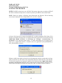
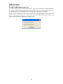

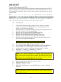
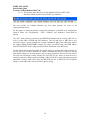


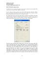
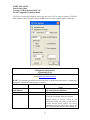


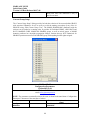
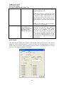
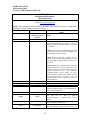

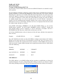


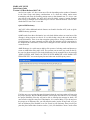

![[U2.06.01] Mise en œuvre d`un calcul de modes](http://vs1.manualzilla.com/store/data/006356197_1-5779fc5c7ebec01bae89c08b91209fe6-150x150.png)


![[U4.52.04] Opérateur MODE_ITER_INV](http://vs1.manualzilla.com/store/data/006363606_1-c02b6c4eb162a985cf804c06c4f2d2be-150x150.png)

![[U4.52.03] Opérateur MODE_ITER_SIMULT](http://vs1.manualzilla.com/store/data/006360204_1-9848c5c379c7a4dd62a03820a78ec9c9-150x150.png)