1
YAMAHA SCARA ROBOT
YK-X series
YK120X/YK150X
YK180X/YK220X
User’s Manual
ENGLISH
E
E30-Ver. 1.36
Before using the robot
(Be sure to read the following notes.)
At this time, our thanks for your purchase of this YAMAHA YK-X series SCARA
robot.
(1) Please be sure to perform the following tasks before using the robot.
Note that the robot may operate abnormally (abnormal vibration or noise) if
the following work is not carried out.
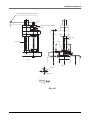
Before the YK-X series is shipped, the position shown in "Chapter 7, 1-2 External view and dimensions" is adjusted as the origin position, and the standard
coordinates are provisionally set.
1. Absolute Reset
Absolute reset must be carried out just once before the YK-X series robot can
be used.
Once absolute reset is completed, it does not need to be carried out again when
the power is turned ON the next time.
Refer to "Chapter 4, 3. Adjusting the origin" in this manual and "Absolute
Reset" in the "YAMAHA Robot Controller User's Manual" for details on absolute reset.
2. Setting the standard coordinates
Set the standard coordinates while referring to instructions in "5. Setting the
Standard coordinates" in Chapter 4 of this manual and also to "Setting the
Standard coordinates" in the "YAMAHA Robot Controller User's Manual".
Robot malfunctions (vibration, noise) may occur if the standard coordinates
are not set correctly.
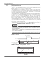
Even though there is no problem with the robot, the following error messages are
issued when the robot and controller are connected and power first turned on.
(Actual error messages may differ according to how the robot and controller are
connected.)
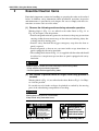
Error messages issued when robot & controller are connected (RCX142)
17.27 : D?.ABS. backup failed (CPU)
17.80 : D?.ABS. backup failed (DRIVER)
17.81 : D?.ABS.battery wire breakage
17.92 : D?.Resolver disconnected during power off
17.93 : D?.Position backup counter overflow
17.94 : D?.ABS.battery low voltage
etc
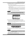
(2) Caution when turning off the robot controller
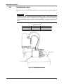
On the YK120X and YK180X series robots, the harness exerts a large reaction
force on the X and Y axis arms. When the power to the robot controller is
turned off, the arm positions might move slightly due to the harness reaction
force, depending on where the arms are positioned. If the arms moved a large
distance in this case, the correct position data may not be backed up. To avoid
this, before turning off the power to the robot controller, press the emergency
stop button and check that the robot arms have completely stopped.
(3) Connection to the controller
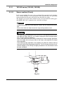
The controller for the YK120X series robots (YK120X, YK150X) is designed
to provide 24V output and the model name "RCX142-T" is shown on the
serial number label (see Fig. 2-5). Do not connect other controllers to the
YK120X series robot. If operated from a controller other than the RCX142T, the robot's motors may be damaged.
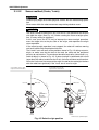
(4) If the X, Y or R axis rotation angle is small
If the X, Y or R axis rotation angle is smaller than 5° so that it always moves
in the same position, an oil film is difficult to be formed on the joint support
bearing, possibly leading to damage to the bearing. In this type of operation,
add a movement so that the joint moves through 90° or more, about 5 times a
day.
(5) Tip weight parameter setting and WEIGHT statement in programs
The tip weight parameter setting and WEIGHT statement in programs for the
YK120X and YK180X series differ from those for other robots.
Refer to “5 Tip weight parameter setting and WEIGHT statement in programs” in Chapter 2 for instructions on how to set these.
(6) Do not remove the Z-axis upper-end mechanical stopper
Removing or moving the upper-end mechanical stopper attached to the Zaxis spline shaft of the YK180X and YK220X series can damage the Z-axis
ball screw. Never remove or move it.
Introduction
The YAMAHA YK120X and YK180 series robots are SCARA type industrial
robots developed based on years of YAMAHA experience and achievements in
the automation field as well as efforts to streamline our in-house manufacturing
systems.
The SCARA robots have a two-joint manipulator consisting of an X-axis arm
and a Y-axis arm, and are further equipped with a vertical axis (Z-axis) and a
rotating axis (R-axis) at the tip of the manipulator. The YK120X and YK180
series robots can be used for a wide range of assembly applications such as
installation and insertion of various parts, application of sealant, and packing
operations.
This user's manual describes the safety measures, handling, adjustment and maintenance of YK120X series robots for correct, safe and effective use. Be sure to
read this manual carefully before installing the robot. Even after you have read
this manual, keep it in a safe and convenient place for future reference.
This user's manual should be used with the robot and considered an integral part
of it. When the robot is moved, transferred or sold, send this manual to the new
user along with the robot. Be sure to explain to the new user the need to read
through this manual.
This user's manual explains the YAMAHA industrial robots YK120X series standard models (YK120X, YK150X), clean room models (YK120XC, YK150XC),
and YK180X series (YK180X, YK220X).
Some descriptions of YK120XC and YK150XC are not listed in this manual when
they are the same as standard models. Refer to the descriptions of standard models.
For information on difference between the clean room model and standard model,
refer to the description on the next page.
For details on specific operation and programming of the robot, refer to the separate
"YAMAHA Robot Controller User's Manual".
NOTES
• The contents of this manual are subject to change without prior notice.
• Information furnished by YAMAHA in this manual is believed to be reliable.
However, if you find any part unclear or inaccurate in this manual, please
contact YAMAHA sales office or dealer.
YAMAHA MOTOR CO., LTD.
IM Company
Clean Room Models YK120XC, YK150XC
Compared to standard YX120X and YK150X, clean room models differ in the
following points.
1. Robot parameter has been changed. (See section 4 in chapter 2.)
The Z-axis speed is lowered to maintain the degree of cleanliness and the
bellows durability. (This is preset prior to shipment.)
2. Suction couplers have been added. (See section 6 in chapter 3.)
For the suction amount versus degree of cleanliness, see "1-1 Basic
specifications" in chapter 7. For the location of the suction couplers, see "12 External view and dimensions" in chapter 7.
The suction amount for each suction coupler is very important to maintain
the degree of cleanliness and the bellows durability, so always comply with
the instruction.
3. R-axis machine reference adjustment is different.
(See section 3-4-1-2 in chapter 4.)
The structure around the R-axis origin sensor differs from standard
specifications, so the method for adjusting the machine reference is different.
Since the Z-axis bellows type suction tube is attached to the R-axis, care
must be taken when performing return-to-origin so that the suction tube will
not entangle around the R-axis.
4. Different grease is used for the Z-axis drive mechanism.
(See section 4 in chapter 5.)
LG2 grease (NSK) suitable for clean room is used for the Z-axis ball screw,
ball spline and linear bushing shaft.
Use the LG2 clean room grease for periodic maintenance.
5. Specifications and external appearance are somewhat changed.
(See sections 1-1 and 1-2 in chapter 7.)
The X- and Y-axis repeated positioning accuracy and Z-axis maximum speed
are different from standard specifications.
The external appearance and dimensions are different in that the Z-axis
bellows, flexible tube and suction couplers are added.
CONTENTS
CHAPTER 1 Using the Robot Safely
1
Safety Information ...................................................................................1-1
2
Essential Caution Items ...........................................................................1-2
3
Special Training for Industrial Robot Operation .....................................1-10
4
Robot Safety Functions ......................................................................... 1-11
5
Safety Measures for the System ...........................................................1-12
6
Trial Operation .......................................................................................1-13
7
Work Within the Safeguard Enclosure ...................................................1-14
8
Automatic Operation ..............................................................................1-15
9
Adjustment and Inspection ....................................................................1-15
10 Repair and Modification .........................................................................1-15
11 Warranty ................................................................................................1-16
12 CE Marking ............................................................................................1-18
CHAPTER 2 Functions
1
Robot Manipulator ...................................................................................2-1
2
Robot Controller ......................................................................................2-5
3
Robot initialization number list .................................................................2-6
4
Parameters for Clean Room Models YK120XC, YK150XC .....................2-7
5
Tip weight parameter setting and WEIGHT statement in programs ........2-8
CHAPTER 3 Installation
1
Robot Installation Conditions ...................................................................3-1
1-1
1-2
2
Installation ...............................................................................................3-5
2-1
2-2
2-3
2-4
3
Installation environments ...................................................................................... 3-1
Installation base ................................................................................................... 3-3
Unpacking ............................................................................................................
Checking the product ...........................................................................................
Moving the robot ...................................................................................................
Installing the robot ................................................................................................
3-5
3-6
3-7
3-8
Protective Bonding ..................................................................................3-9
4
Robot Cable Connection ....................................................................... 3-11
5
User Wiring and User Tubing ................................................................3-13
6
Connecting a suction hose (YK120XC, YK150XC) ...............................3-16
7
Attaching The End Effector ....................................................................3-17
7-1
7-2
7-3
7-4
7-5
8
R-axis tolerable moment of inertia and acceleration coefficient ......................... 3-17
7-1-1
Acceleration coefficient vs. moment of inertia (YK120X) ..................................... 3-19
7-1-2
Acceleration coefficient vs. moment of inertia (YK150X) ..................................... 3-21
7-1-3
Acceleration coefficient vs. moment of inertia (YK180X, YK220X) ...................... 3-23
Equation for moment of inertia calculation .........................................................
Example of moment of inertia calculation ...........................................................
Attaching the end effector ..................................................................................
Gripping force of end effector .............................................................................
3-24
3-27
3-29
3-32
Working Envelope and Mechanical Stopper Positions for Maximum Working Envelope ... 3-33
CHAPTER 4 Adjustment
1
Overview ..................................................................................................4-1
2
Safety Precautions ..................................................................................4-1
3
Adjusting the origin ..................................................................................4-2
3-1
Absolute reset method ......................................................................................... 4-3
3-1-1
3-1-2
3-2
3-3
3-4
YK120X series (YK120X, YK150X) ........................................................................ 4-3
3-1-1-1
Sensor method (R-axis) ........................................................................................ 4-3
3-1-1-2
Stroke end method (X-axis, Y-axis) ...................................................................... 4-4
3-1-1-3
Stroke end method (Z-axis) .................................................................................. 4-6
YK180X series (YK180X, YK220X) ........................................................................ 4-7
3-1-2-1
Sensor method (R-axis) ........................................................................................ 4-7
3-1-2-2
Sensor method (X-axis, Y-axis) ............................................................................ 4-8
3-1-2-3
Stroke end method (Z-axis) .................................................................................. 4-9
Machine reference.............................................................................................. 4-10
Absolute reset procedures .................................................................................. 4-11
3-3-1
Sensor method (R-axis) ....................................................................................... 4-11
3-3-2
Stroke end method (X and Y axes of YK120X, YK150X) ..................................... 4-13
3-3-3
Stroke end method (Z-axis) .................................................................................. 4-15
3-3-4
Sensor method (X and Y axes of YK180X, YK220X) ........................................... 4-16
Adjusting the machine reference ........................................................................ 4-18
3-4-1
YK120X series (YK120X, YK150X) ...................................................................... 4-19
3-4-1-1
Adjusting the R-axis machine reference (YK120X, YK150X) ............................. 4-19
3-4-1-2
Adjusting the R-axis machine reference (YK120XC, YK150XC) ........................ 4-21
3-4-1-3
Adjusting the X-axis machine reference ............................................................. 4-23
3-4-1-4
Adjusting the Y-axis machine reference .............................................................. 4-25
3-4-1-5
Adjusting the Z-axis machine reference ............................................................. 4-27
3-4-2
YK180X series (YK180X, YK220X) ...................................................................... 4-30
3-4-2-1
Adjusting the R-axis machine reference (YK180X, YK220X) ............................. 4-30
3-4-2-2
Adjusting the X-axis machine reference ............................................................. 4-32
3-4-2-3
Adjusting the Y-axis machine reference .............................................................. 4-34
3-4-2-4
Adjusting the Z-axis machine reference ............................................................. 4-36
4
Setting the Soft Limits ............................................................................4-39
5
Setting the Standard Coordinates .........................................................4-42
6
Affixing Stickers for Movement Directions and Axis Names ..................4-43
7
Removing the Robot Covers .................................................................4-45
CHAPTER 5 Periodic Inspecition
1
Overview ..................................................................................................5-1
2
Precautions ..............................................................................................5-2
3
Daily Inspection .......................................................................................5-3
4
Six-Month Inspection ...............................................................................5-5
5
Replacing the Harmonic Drive Grease ....................................................5-8
5-1
Replacement period ............................................................................................. 5-8
CHAPTER 6 Increasing the robot operating speed
1
Increasing the robot operating speed ......................................................6-1
CHAPTER 7 Specifications
1
Manipulator ..............................................................................................7-1
1-1
1-2
1-3
1-4
Basic specification ................................................................................................ 7-1
External view and dimensions .............................................................................. 7-2
Robot inner wiring diagram ................................................................................ 7-14
Wiring table ........................................................................................................ 7-15
MEMO
CHAPTER 1
Using the Robot Safely
1
Safety Information ...................................................................................1-1
2
Essential Caution Items ...........................................................................1-2
3
Special Training for Industrial Robot Operation .....................................1-10
4
Robot Safety Functions ......................................................................... 1-11
5
Safety Measures for the System ...........................................................1-12
6
Trial Operation .......................................................................................1-13
7
Work Within the Safeguard Enclosure ...................................................1-14
8
Automatic Operation ..............................................................................1-15
9
Adjustment and Inspection ....................................................................1-15
10 Repair and Modification .........................................................................1-15
11 Warranty ................................................................................................1-16
12 CE Marking ............................................................................................1-18
MEMO
CHAPTER 1 Using the Robot Safely
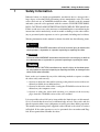
1
Safety Information
Industrial robots are highly programmable, mechanical devices that provide a
large degree of freedom when performing various manipulative tasks. To ensure
correct and safe use of YAMAHA industrial robots, carefully read this manual
and make yourself well acquainted with the contents. FOLLOW THE WARNINGS, CAUTIONS AND INSTRUCTIONS INCLUDED IN THIS MANUAL.
Failure to take necessary safety measures or mishandling due to not following the
instructions in this manual may result in trouble or damage to the robot and injury to personnel (robot operator or service personnel) including fatal accidents.
Warning information in this manual is shown classified into the following items.
DANGER
Failure to follow DANGER instructions will result in severe injury or death to the
robot operator, a bystander or a person inspecting or repairing the robot.
WARNING
Failure to follow WARNING instructions could result in severe injury or death to
the robot operator, a bystander or a person inspecting or repairing the robot.
! CAUTION
Failure to follow CAUTION instructions may result in injury to the robot operator, a bystander or a person inspecting or repairing the robot, or damage to the
robot and/or robot controller.
Refer to the user's manual by any of the following methods to operate or adjust
the robot safely and correctly.
1. Operate or adjust the robot while referring to the printed version of the user's
manual (available for an additional fee).
2. Operate or adjust the robot while viewing the CD-ROM version of the user's
manual on your computer screen.
3. Operate or adjust the robot while referring to a printout of the necessary
pages from the CD-ROM version of the user's manual.
It is not possible to detail all safety items within the limited space of this manual.
So it is essential that the user have a full knowledge of basic safety rules and also
that the operator makes correct judgments on safety procedures during operation.
This manual and warning labels supplied with or affixed to the robot are written
in English. If the robot operator or service personnel does not understand English, do not permit him to handle the robot.
1-1
CHAPTER 1 Using the Robot Safely
2
Essential Caution Items
Particularly important cautions for handling or operating the robot are described
below. In addition, safety information about installation, operation, inspection
and maintenance is provided in each chapter. Be sure to comply with these instructions to ensure safe use of the robot.
(1) Observe the following cautions during automatic operation.
Warning labels 1 (Fig. 1-1) are affixed to the robot. Refer to Fig. 2-2 to
Fig. 2-4 in Chapter 2 for the position.
• Install a safeguard enclosure (protective enclosure) to keep any person from
entering within the movement range of the robot and suffering injury due
to being struck by moving parts.
• Install a safety interlock that triggers emergency stop when the door or
panel is opened.
• Install safeguards so that no one can enter inside except from doors or
panels equipped with safety interlocks.
• The warning labels shown in Fig. 1-1 are supplied with the robot and should
be affixed to a conspicuous spot on doors or panels equipped with safety
interlocks.
DANGER
Serious injury or death will result from impact with moving robot.
• Keep outside of guard during operation.
• Lock out power before approaching robot.
(2) Use caution to prevent hands or fingers from being pinched or
crushed.
Warning labels 2 (Fig. 1-2) are affixed to the robot. Refer to Fig. 2-2 in Chapter 2 for the position.
Be careful not to let hands or fingers be pinched or crushed by the moving
parts of the robot during transportation or teaching.
WARNING
Moving parts can pinch or crush hands.
Keep hands away from robot arms.
DANGER
WARNING
Serious injury or death
will result from impact
with moving robot.
• Keep outside of guard
during operation.
• Lock out power before
approaching robot.
■Fig. 1-1 Warning label 1
1-2
Moving parts can
pinch or crush.
Keep hands away
from robot arms.
■Fig. 1-2 Warning label 2
CHAPTER 1 Using the Robot Safely
(3) Follow the instructions on warning labels and in this manual.
Warning label 3 (Fig. 1-3) is affixed to the robot. Refer to Fig. 2-2 to
Fig. 2-4 in Chapter 2 for the position.
• Be sure to read the warning label and this manual carefully and make you
thoroughly understand the contents before attempting installation and operation of the robot.
• Before starting the robot operation, even after you have read through this
manual, read again the corresponding procedures and cautions in this manual
as well as descriptions in this chapter (Chapter 1, "Using the Robot Safely").
• Never install, adjust, inspect or service the robot in any manner that does
not comply with the instructions in this manual.
WARNING
Improper installation or operation can result in serious injury or death.
Read user's manual and all warning labels before installation or operation.
WARNING
Improper Installation or operation
can result in serious injury or
death.
Read user's(owner's)
manual and all warning labels
before operation.
■Fig. 1-3 Warning label 3
(4) Do not remove the Z-axis upper-end mechanical stopper
Removing or moving the upper-end mechanical stopper attached to the Zaxis spline shaft of the YK180X and YK220X series can damage the Z-axis
ball screw. Never remove or move it.
! CAUTION
Do not remove this part. Damage to the ball screw will result.
■Fig. 1-4 Warning label 4
(5) Do not use the robot in environments containing inflammable
gas, etc.
WARNING
• This robot was not designed for operation in environments where inflammable or explosive substances are present.
• Do not use the robot in environments containing inflammable gas, dust or
liquids. Explosions or fire could otherwise result.
1-3
CHAPTER 1 Using the Robot Safely
(6) Do not use the robot in locations possibly subject to electromagnetic interference, etc.
WARNING
Avoid using the robot in locations subject to electromagnetic interference, electrostatic discharge or radio frequency interference. Malfunction may otherwise
occur.
(7) Use caution when releasing the Z-axis (vertical axis) brake.
WARNING
The Z-axis will slide down when the Z-axis brake is released, causing a hazardous situation.
• Press the emergency stop button and prop up the Z-axis with a support stand
before releasing the brake.
• Use caution not to let your body get caught between the Z-axis and installation base when releasing the brake to perform direct teach.
(8) Provide safety measures for end effector (gripper, etc.).
WARNING
• End effectors must be designed and manufactured so that they cause no
hazards (for example, loosening of workpiece) even if power (electricity, air
pressure, etc.) is shut off or power fluctuations occur.
• If there is a possible danger that the object gripped by the end effector may
fly off or drop, then provide appropriate safety protection taking into account
the object size, weight, temperature and chemical properties.
(9) Be cautious of possible Z-axis movement when the controller is
turned off or emergency stop is triggered. (2-axis robots with
air-driven Z-axis)
WARNING
The Z-axis moves up when the power to the controller or PLC is turned off, the
program is reset, emergency stop is triggered, or air is supplied to the solenoid
valve for the Z-axis air cylinder.
• Do not let hands or fingers get caught and squeezed by moving parts of the
Z-axis.
• Keep the usual robot position in mind so that the Z-axis will not interfere with
obstacles during raising of the Z-axis, except in case of emergency stop.
1-4
CHAPTER 1 Using the Robot Safely
(10) Use the following caution items when the Z-axis is interfering
with peripheral equipment. (2-axis robots with air driven Z-axis)
WARNING
When the Z-axis comes to a stop due to obstructions from peripheral equipment, the Z-axis may move suddenly when the obstruction is removed, causing
injury such as pinched or crushed hands.
• Turn off the controller and reduce the air pressure before attempting to remove the obstruction.
• Before reducing the air pressure, place a support stand under the Z-axis
because it will drop under its own weight.
(11) Use caution on Z-axis movement when air supply is stopped. (2axis robots with air-driven Z-axis)
WARNING
The Z-axis may suddenly drop when the air pressure to the Z-axis air cylinder
solenoid valve is reduced, creating a hazardous situation.
Turn off the controller and place a prop or support under the Z-axis before
cutting off the air supply.
(12) Use the following caution items when disassembling or replacing the pneumatic equipment.
WARNING
Air or parts may fly outwards if pneumatic equipment is disassembled or parts
replaced while air is still supplied.
• Do service work after first turning off the controller and reducing the air pressure.
• Before reducing the air pressure, place a support stand under the Z-axis (2axis robots with air driven Z-axis) since it will drop under its own weight.
(13) Cautions for removing Z-axis brake or Z-axis motor
WARNING
The Z-axis can drop and cause a hazard when the Z-axis brake or Z-axis motor
is removed.
• Turn off the controller and set a support stand under the Z-axis before removing the motor.
• Use caution not to allow hands or body to be squeezed or crushed by moving
parts on the Z-axis or between the Z-axis and the installation base.
1-5
CHAPTER 1 Using the Robot Safely
(14) Use the following caution during inspection of controller.
WARNING
• When you need to touch the terminals or connectors on the outside of the
controller during inspection, always first turn off the controller power switch
and also the power source in order to prevent possible electrical shock.
• Never touch any internal parts of the controller.
For precautions on handling the controller, refer to the "YAMAHA Robot Controller User's Manual".
(15) Consult us for corrective action when the robot is damaged or
malfunction occurs.
WARNING
If any part of the robot is damaged or any malfunction occurs, continuous operation may be very dangerous. Please consult YAMAHA dealer for corrective
action.
Damage or Trouble
Possible Danger
Damage to machine harness or robot cable
Electrical shock, malfunction of robot
Damage to exterior of robot
Flying outwards of damaged parts during robot
operation
Abnormal operation of robot
(positioning error, excessive vibration, etc.)
Malfunction of robot
Z-axis brake trouble
Dropping of load
(16) Use caution not to touch the controller rear panel cooling fan.
WARNING
• Bodily injury may occur from coming into contact with the cooling fan while it
is rotating.
• When removing the fan cover for inspection, first turn off the controller and
make sure the fan has stopped.
(17) Use caution not to touch the high temperature motor or speed
reduction gear casing.
WARNING
The motor and speed reduction gear casing are extremely hot after automatic
operation, so burns may occur if these are touched.
Before touching these parts during inspections or servicing, turn off the controller, wait for a while and check that the temperature has cooled.
1-6
CHAPTER 1 Using the Robot Safely
(18) Do not remove, alter or stain the warning labels.
WARNING
If warning labels are removed or difficult to see, necessary cautions may not be
taken, resulting in an accident.
• Do not remove, alter or stain the warning labels on the robot.
• Do not allow the warning labels to be hidden by the device installed to the
robot by the user.
• Provide proper lighting so that the symbols and instructions on the warning
labels can be clearly seen even from the outside of safeguards.
(19) Protective bonding
WARNING
Be sure to ground the robot and controller to prevent electrical shock.
(20) Always connect the robot to the specified controller.
WARNING
The controller for the YK120X series robots (YK120X, YK150X) is designed to
provide 24V output and the model name "RCX142-T" is shown on the serial
number label (see Fig. 2-5). Do not connect other controllers to the YK120X
series robot. If operated from a controller other than the RCX142-T, the robot's
motors may be damaged.
(21) Avoid fastening any cable or tube prepared by the user with the
machine harness, user signal wires or air tubes of the robot.
WARNING
Do not utilize the machine harness, user signal wires or air tubes of the robot to
fasten any cable or tube prepared by the user, as this may break the robot
harness wires or user signal wires causing malfunction of the robot. This will
also result in poor positioning accuracy.
(22) Do not use the robot in locations subject to strong vibrations.
WARNING
Do not operate the robot in locations subject to strong vibrations. The robot
installation bolts might work loose and the robot topple over. The bolts on the
robot body itself might also loosen, causing parts to fall off, etc.
1-7
CHAPTER 1 Using the Robot Safely
(23) Be sure to make correct parameter settings.
! CAUTION
The robot must be operated with correct tolerable moment of inertia and acceleration coefficients according to the manipulator tip mass and moment of inertia. If this is not observed, premature end to the life of the drive units, damage to
the robot parts or residual vibration during positioning may result.
(24) Do not use the robot for tasks requiring motor thrust.
! CAUTION
Avoid using the YK-X series robots for tasks which make use of motor thrust
(press-fitting, burr removal, etc.). These tasks may cause malfunctions of the
robot.
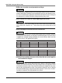
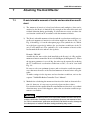
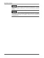
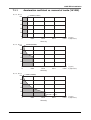
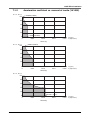
(25) Do not apply excessive force to each section.
! CAUTION
The YK120X series (YK120X, YK150X) and YK180X series (YK180X, YK220X)
are designed to be compact, so the joints could be damaged if excessive force
is applied, for example, during installation of an end effector. Make sure that
excessive force is not applied to the joints.
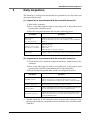
YK120X, YK150X
Axis
Tolerable radial load Tolerable thrust load Tolerable moment load
Tolerable torque
X-axis
100N (10.2kgf)
100N (10.2kgf)
1.5Nm (15.3kgfcm)
1.7Nm (17.3kgfcm)
Y-axis
45N (4.6kgf)
45N (4.6kgf)
0.45Nm (4.6kgfcm)
0.5Nm (5.1kgfcm)
R-axis
45N (4.6kgf)
45N (4.6kgf)
0.45Nm (4.6kgfcm)
0.3Nm (3.1kgfcm)
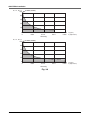
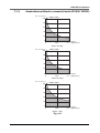
YK180X, YK220X
Axis
Tolerable radial load Tolerable thrust load Tolerable moment load
Tolerable torque
X-axis
275N (28.1kgf)
900N (91.8kgf)
6.0Nm (61.2kgfcm)
9.0Nm (91.8kgfcm)
Y-axis
150N (15.3kgf)
600N (61.2kgf)
3.3Nm (33.7kgfcm)
4.0Nm (40.8kgfcm)
R-axis
150N (15.3kgf)
600N (61.2kgf)
3.3Nm (33.7kgfcm)
2.2Nm (22.4kgfcm)
(26) Check the machine reference value when the arm struck against
the mechanical stopper.
! CAUTION
When the arm moves at high speed and strikes against a mechanical stopper
violently, the machine reference value may change. If this has happened, check
the machine reference value. Also check the mechanical stopper for any damage and the origin position for shift. If the machine reference value is outside
the recommended range, adjust the machine reference. In this case, re-teaching may be required if the origin position has shifted.
1-8
CHAPTER 1 Using the Robot Safely
(27) Use caution not to apply excessive force to the machine harness, user signal cables and air tubes.
! CAUTION
A positioning error may occur if excessive force is applied to the machine harness, user signal cables or air tubes. A positioning error may also occur if the
machine harness, user signal cables or air tubes have deteriorated due to improper installation environment.
(28) Caution when turning off the robot controller
! CAUTION
The XY arm positions might move slightly due to the harness reaction force
when the power to the robot controller is turned off, making it difficult to back up
the correct position data. To avoid this, before turning off the power to the robot
controller, press the emergency stop button and check that the robot arms have
completely stopped.
(29) Take the following precautions when transporting the robot.
! CAUTION
If the robot is transported long distances by truck while mounted on an installation base or packed in a case other than the dedicated carton box in which the
robot was shipped, the bolts installing the robot or the bolts on the robot body
itself might come loose due to vibration. The robot might then topple over or the
parts fall off.
When transporting the robot long distances, use the dedicated case in which
the robot was shipped from our factory.
(30) If the X, Y or R axis rotation angle is small
! CAUTION
If the X, Y or R axis rotation angle is smaller than 5° so that it always moves in
the same position, an oil film is difficult to be formed on the joint support bearing, possibly leading to damage to the bearing. In this type of operation, add a
movement so that the joint moves through 90° or more, about 5 times a day.
1-9
CHAPTER 1 Using the Robot Safely
3
Special Training for Industrial Robot Operation
Companies or factories using industrial robots must make sure that every person,
who operates or handles the robot such as for teaching, programming, movement
check, inspection, adjustment and repair, has received appropriate training and
also has the skills needed to perform the job correctly and safely.
Since the YK120X and YK180X series robots fall under the industrial robot category, the user must observe local regulations and safety standards for industrial
robots, and provide special training for every person involved in robot-related
tasks (teaching, programming, movement check, inspection, adjustment, repair,
etc.).
1-10
CHAPTER 1 Using the Robot Safely
4
Robot Safety Functions
(1) Overload detection
This function detects an overload applied to the motor and shuts off the servo
power. If an overload error occurs, take the following measures.
1. Insert a timer in the program.
2. Reduce the acceleration coefficient.
(2) Overheat detection
This function detects an abnormal temperature rise in the driver inside the
controller and shuts off the servo power. If an overheat error occurs, take the
following measures.
1. Insert a timer in the program.
2. Reduce the acceleration coefficient.
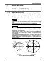
(3) Soft limits
Soft limits can be set on each axis to limit the working envelope in manual
operation after return-to-origin and during automatic operation.
Note: The working envelope is the area limited by soft limits.
(4) Mechanical stoppers
If the servo power is suddenly shut off during high-speed operation by emergency stop or safety functions, these mechanical stoppers prevent the axis
from exceeding the movement range.
On the X-axis, Y-axis arm, mechanical stoppers are fixed at both ends of the
maximum movement range.
The Z-axis has a mechanical stopper at the upper end and lower end.
No mechanical stopper is provided on the R-axis.
Note: The movement range is the area limited by mechanical stoppers.
WARNING
Axis movement will not stop immediately after the servo power supply is shut
off by emergency stop or other safety functions.
(5) Z-axis (vertical axis) brake
An electromagnetic brake is installed on the Z-axis to prevent the Z-axis
from sliding down when servo power is turned off. This brake is working
when the controller is off or the Z-axis servo power is off even when the
controller is on. The Z-axis brake can be released by means of the programming unit or by a command in the program when the controller is on.
WARNING
The Z-axis will slide down when the Z-axis brake is released, creating a hazardous situation.
• Press the emergency stop button and prop the Z-axis with a support stand
before releasing the brake.
• Use caution not to let your body get caught between the Z-axis and installation base when releasing the brake to perform direct teach.
1-11
CHAPTER 1 Using the Robot Safely
5
Safety Measures for the System
Since the robot is commonly used in conjunction with an automated system, dangerous situations are more likely to occur from the automated system than from
the robot itself. Accordingly, appropriate safety measures must be taken on the
part of the system manufacturer according to the individual system. The system
manufacturer should provide a proper user's manual for safe, correct operation
and servicing of the system.
1-12
CHAPTER 1 Using the Robot Safely
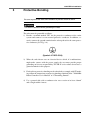
6
Trial Operation
After making installations, adjustments, inspections, maintenance or repairs to
the robot, make a trial run using the following procedures.
(1) If a safeguard enclosure has not yet been provided right after installation of
the robot, rope off or chain off around the movement area of the manipulator
in place of the safeguard enclosure, and observe the following points.
1. Use sturdy, stable posts which will not fall over easily.
2. The rope or chain should be easily visible by everyone around the robot.
3. Place a sign to keep the operator or other personnel from entering the
movement range of the manipulator.
(2) Check the following points before turning on the controller.
1. Is the robot securely and correctly installed?
2. Are the electrical connections to the robot correct?
3. Are items such as air pressure correctly supplied?
4. Is the robot correctly connected to peripheral equipment?
5. Have safety measures (safeguard enclosure, etc.) been taken?
6. Does the installation environment meet the specified standards?
(3) After the controller is turned on, check the following points from outside the
safeguard enclosure.
1. Does the robot start and stop as intended? Can the operation mode be
selected correctly?
2. Does each axis move as intended within the soft limits?
3. Does the end effector move as intended?
4. Are the signal transmissions to the end effector and peripheral equipment
correct?
5. Does emergency stop work?
6. Are the teaching and playback functions normal?
7. Are the safeguard enclosure and interlock working as intended?
8. Does the robot move correctly during automatic operation?
1-13
CHAPTER 1 Using the Robot Safely
7
Work Within the Safeguard Enclosure
(1) When work is required inside the safeguard enclosure, always turn off the
controller and place a sign indicating that the robot is being adjusted or serviced in order to keep any other person from touching the controller switch or
operation panel, except for the following cases.
1) Adjusting the Z-axis machine reference (See Section 3-4-1-5 in Chapter
4.)
2) Setting the Soft Limits (See Section 4 in Chapter 4.)
3) Setting the Standard Coordinates (See Section 5 in Chapter 4.)
4) Teaching
For items 1) to 3), follow the precautions and procedure for each section. To
perform item 4), refer to the description in (2) below.
(2) Teaching
When performing teaching within the safeguard enclosure, comply with the
instructions listed below.
1) Check or perform the following points from outside the safeguard enclosure.
1. Make sure that no hazards are present within the safeguard enclosure
by a visual check.
2. Check that the programming unit MPB operates correctly.
3. Check that no failures are found in the robot.
4. Check that emergency stop works correctly.
5. Select teaching mode and prohibit automatic operation.
2) Never enter the movement range of the manipulator while within the safeguard enclosure.
1-14
CHAPTER 1 Using the Robot Safely
8
Automatic Operation
Automatic operation described here includes all operations in AUTO mode.
(1) Check the following before starting automatic operation.
1. No one is within the safeguard enclosure.
2. The programming unit and tools are in their specified locations.
3. The alarm or error lamps on the robot and peripheral equipment do not
flash.
4. The safeguard enclosure is securely installed with safety interlocks actuated.
(2) Observe the following during automatic operation or in cases where an error
occurs.
1) After automatic operation has started, check the operation status and warning lamp to ensure that the robot is in automatic operation.
2) Never enter the safeguard enclosure during automatic operation.
3) If an error occurs in the robot or peripheral equipment, observe the following procedure before entering the safeguard enclosure.
1. Press the emergency stop button to set the robot to emergency stop.
2. Place a sign on the start switch, indicating that the robot is being inspected in order to keep any other person from touching the start switch
and restarting the robot.
9
Adjustment and Inspection
Do not attempt any installation, adjustment, inspection or maintenance unless it
is described in this manual.
10
Repair and Modification
Do not attempt any repair, parts replacement and modification unless described
in this manual. These works require technical knowledge and skill, and may also
involve work hazards.
1-15
CHAPTER 1 Using the Robot Safely
11
Warranty
The YAMAHA robot and/or related product you have purchased are warranted
against the defects or malfunctions as described below.
Warranty description
: If a failure or breakdown occurs due to defects in materials or workmanship in the
genuine parts constituting this YAMAHA
robot and/or related product within the warranty period, then YAMAHA will repair or
replace those parts free of charge (hereafter
called "warranty repair").
Warranty Period
: The warranty period ends when any of the following applies:
(1) After 18 months (one and a half year) have
elapsed from the date of shipment
(2) After one year has elapsed from the date of
installation
(3) After 2,400 hours of operation
Exceptions to the Warranty : This warranty will not apply in the following
cases:
(1) Fatigue arising due to the passage of time,
natural wear and tear occurring during operation (natural fading of painted or plated
surfaces, deterioration of parts subject to
wear, etc.)
(2) Minor natural phenomena that do not affect
the capabilities of the robot and/or related
product (noise from computers, motors,
etc.).
(3) Programs, point data and other internal data
that were changed or created by the user.
Failures resulting from the following causes are not covered by warranty repair.
1) Damage due to earthquakes, storms, floods, thunderbolt, fire or any other
natural or man-made disasters.
2) Troubles caused by procedures prohibited in this manual.
3) Modifications to the robot and/or related product not approved by
YAMAHA or YAMAHA sales representatives.
4) Use of any other than genuine parts and specified grease and lubricants.
5) Incorrect or inadequate maintenance and inspection.
6) Repairs by other than authorized dealers.
1-16
CHAPTER 1 Using the Robot Safely
YAMAHA MOTOR CO., LTD. MAKES NO OTHER EXPRESS OR IMPLIED
WARRANTIES, INCLUDING ANY IMPLIED WARRANTY OF
MERCHANTABILITY OR FITNESS FOR ANY PARTICULAR PURPOSE.
THE WARRANTY SET FORTH ABOVE IS EXCLUSIVE AND IS IN LIEU
OF ALL EXPRESSED OR IMPLIED WARRANTIES, INCLUDING WARRANTIES OF MERCHANTABILITY, FITNESS FOR A PARTICULAR PURPOSE,
OR WARRANTIES ARISING FROM A COURSE OF DEALING OR USAGE
OF TRADE.
YAMAHA MOTOR CO., LTD. SOLE LIABILITY SHALL BE FOR THE DELIVERY OF THE EQUIPMENT AND YAMAHA MOTOR CO., LTD. SHALL
NOT BE LIABLE FOR ANY CONSEQUENTIAL DAMAGES (WHETHER
ARISING FROM CONTRACT, WARRANTY, NEGLIGENCE OR STRICT
LIABILITY). YAMAHA MOTOR CO., LTD. MAKES NO WARRANTY WHATSOEVER WITH REGARD TO ACCESSORIES OR PARTS NOT SUPPLIED
BY YAMAHA MOTOR CO., LTD.
1-17
CHAPTER 1 Using the Robot Safely
12
CE Marking
When the YAMAHA robots are exported to or used in EU (European Union)
countries, refer to the separate "YAMAHA Robot Controller User's Manual" or
"CE marking manual" for related information about CE marking.
1-18
CHAPTER 2
Functions
1
Robot Manipulator ...................................................................................2-1
2
Robot Controller ......................................................................................2-5
3
Robot initialization number list .................................................................2-6
4
Parameters for Clean Room Models YK120XC, YK150XC .....................2-7
5
Tip weight parameter setting and WEIGHT statement in programs ........2-8
MEMO
CHAPTER 2 Functions
1
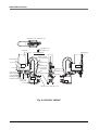
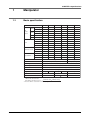
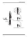
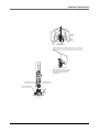
Robot Manipulator
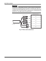
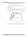
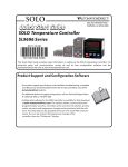
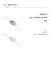
The YK-X series robots are available in 4-axis models having an X/Y-axis arm
(equivalent to human arm) and a Z/R-axis (equivalent to human wrist).
With these 4 axes, the YK-X series robots can move as shown in Fig. 2-1. By
attaching different types of end effector (gripper) to the end of the arm, a wide
range of tasks can be performed with high precision at high speeds.
The (+) and (-) signs show the direction of axis movement when the jog keys on
the programming unit are pressed (standard setting at the factory). Fig. 2-2 to Fig.
2-4 on the subsequent pages show part names and functions of each robot model.
Y-axis arm
X-axis arm
(+)
(–)
Y-axis
(–)
X-axis
(+)
(–)
Z-axis
(+)
(–)
R-axis
(+)
Fig. 2-1 Manipulator movement
2-1
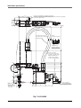
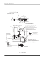
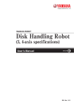
CHAPTER 2 Functions
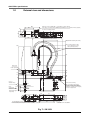
Connector for user wiring (No.1 to 6)
Linear busing shaft
Ball screw
Warning label 2
Machine harness
Warning label 1
User tubing 2 (φ3)
Z-axis motor
User air tube
User tubing 1 (φ3)
R-axis motor
Viewed from direction A
User signal cable
X-axis mechanical stopper
Y-axis motor
Y-axis
mechanical
stopper
Y-axis arm
User tubing 2 (φ3)
User tubing 1 (φ3)
X-axis arm
X-axis speed
reduction gear
R-axis speed
reduction gear
Y-axis speed
reduction gear
Z-axis brake
Z-axis spline
M3 ground terminal
End effector attachment
Robot cable
Connector for user wiring (No.1 to 6)
X-axis motor
Warning label 3
User tap (* four positions)
Fig. 2-2 YK120X, YK150X
2-2
Serial label
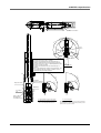
CHAPTER 2 Functions
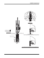
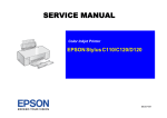
Connector for user wiring (No.1 to 6)
Ball screw
Machine harness
Linear busing shaft
Bellows
type suction coupler
User tubing 2
(φ3)
Warning label 1
User tubing 1 (φ3)
Y-axis motor
Z-axis motor
Viewed from direction A
Warning label 2
R-axis motor
Y-axis
mechanical stopper
M3 ground terminal
X-axis speed
reduction gear
Y-axis arm
R-axis speed
reduction gear
Bellows
type suction coupler
Bellows
X-axis mechanical stopper
Bellows
type suction coupler (φ3)
Connector for user wiring
(No.1 to 6)
Y-axis speed
reduction gear
Z-axis brake
User tubing 2
(φ3)
User tubing 1
(φ3)
X-axis arm
End effector attachment
Warning label 3
X-axis motor
Suction coupler for base interior (φ6)
Robot cable
Suction coupler for X, Y and R axis joints
Fig. 2-3 YK120XC, YK150XC
2-3
Serial label
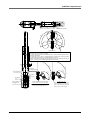
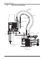
CHAPTER 2 Functions
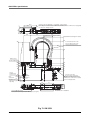
Connector for user wiring (No.1 to 6)
User tubing 2 (φ3)
Ball screw
User tubing 1 (φ3)
Y-axis motor
Warning label 2
Viewed from direction A
Machine harness
User signal cable
Warning label 1
Y-axis
mechanical stopper
R-axis motor
X-axis
mechanical stopper
Y-axis arm
X-axis speed
reduction gear
A
User tubing 2 (φ3)
User tubing 1 (φ3)
R-axis speed
reduction gear
Y-axis speed
Z-axis spline
reduction gear
Warning label 4
X-axis arm
End effector attachment
Z-axis motor
Z-axis brake
M3 ground terminal
Robot cable
X-axis motor
Warning label 3
Serial label
Connector for user wiring (No.1 to 6)
Fig. 2-4 YK180X, YK220X
2-4
CHAPTER 2 Functions
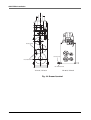
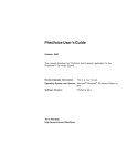
2
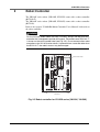
Robot Controller
The YK120X series robots (YK120X, YK150X) come with a robot controller
(RCX142-T).
The YK180X series robots (YK180X, YK220X) come with a robot controller
(RCX142).
Refer to the separate "YAMAHA Robot Controller User's Manual" for details on
the robot controller.
WARNING
For the YK120X series robots (YK120X, YK150X), always use the RCX142-T
controller that is designed to provide 24V output. The model name "RCX142-T"
is shown on the serial number label (see Fig. 2-5). Do not connect other robot
controllers to the YK120X series robots. If operated from a controller other than
the RCX142-T, the robot's motors may be damaged.
OP.1
MOTOR
PWR
OP.3
MPB
RCX142
MODEL.
SRV
Serial number label
SER. NO.
MANUFACTURED
XM
ERR
FACTORY AUTOMATION EQUIPMENT MADE IN JAPAN
ROB
I/O
XY
YM
BATT
COM
XY
ROB
I/O
ZR
ZR
OP.2
OP.4
RGEN
ZM
STD.DIO
P
SAFETY
N
ACIN
RM
L
N
200-230V~
50-60Hz
MAX.300VA
RCX142-T
Fig. 2-5 Robot controller for YK120X series (YK120X, YK150X)
2-5
CHAPTER 2 Functions
3
Robot initialization number list
The YK-X series robots are initialized for optimum setting (default setting) according to the robot model prior to shipping. The robot controllers do not have to
be reinitialized during normal operation. However, if for some reason the controller must be reinitialized, proceed while referring to the list below.
! CAUTION
Absolute reset must be performed after reinitializing the controller.
Before reinitializing the controller, read the descriptions in "3. Adjusting the origin" in Chapter 4 and make sure you thoroughly understand the procedure.
! CAUTION
When the controller is initialized, the "ARM LENGTH" and "OFFSET PULSE"
settings in the axis parameters will be erased, making the standard coordinate
settings invalid.
(Refer to "Chapter 4 Setting the Standard Coordinates" for details on the standard coordinates.)
Write down the "arm length" and "offset pulse" values before hand, and input
each value again after completing the initialization process.
Robot initialization number
Robot initialization number
Robot model name
Applicable models
2020
YK120X
YK120X, YK120XC
2021
YK150X
YK150X, YK150XC
2115
YK180X
YK180X
2116
YK220X
YK220X
2-6
CHAPTER 2 Functions
4
Parameters for Clean Room Models YK120XC,
YK150XC
Part of robot parameters on clean room models has been changed to maintain the
degree of cleanliness and the Z-axis bellows durability.
Along with this robot parameter change shown below, you must take the following precautions.
To purchasers of this robot
At this time our sincere thanks for your purchase of our robot.
Since this robot is custom designed and manufactured, a robot parameter has
been changed from the standard specifications. Please keep this sheet carefully
along with the user's manual.
Check the following points before using the robot.
Precautions during use
Always make a backup of robot parameters.
Initializing the parameters deletes previous parameter settings. If necessary, load
the backup parameters.
Parameter changes
The following parameter has been changed. Blank portions indicate standard specifications are used.
Axis settings
Parameter No.
Name
M1
PRM37
Max. motor rotation
2-7
Changes
M2
M3
1500
M3
CHAPTER 2 Functions
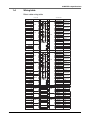
5
Tip weight parameter setting and WEIGHT
statement in programs
The tip weight parameter setting and WEIGHT statement in programs for the YK120X
and YK180X series differ from those for other robots. Set the tip weight parameter
and WEIGHT statement to match the actual load as shown in the table below.
If this is not observed, drive units will be damaged or the service life will shorten.
Actual load [kg]
Tip weight parameter [×0.1kg]
WEIGHT
0
0.1
0.2
0.3
0.4
0.5
0.6
0.7
0.8
0.9
1.0
0
1
2
3
4
5
6
7
8
9
10
WEIGHT 0
WEIGHT 1
WEIGHT 2
WEIGHT 3
WEIGHT 4
WEIGHT 5
WEIGHT 6
WEIGHT 7
WEIGHT 8
WEIGHT 9
WEIGHT 10
2-8
CHAPTER 3
Installation
1
Robot Installation Conditions ...................................................................3-1
1-1
1-2
2
Installation environments ...................................................................................... 3-1
Installation base ................................................................................................... 3-3
Installation ...............................................................................................3-5
2-1
2-2
2-3
2-4
Unpacking ............................................................................................................
Checking the product ...........................................................................................
Moving the robot ...................................................................................................
Installing the robot ................................................................................................
3-5
3-6
3-7
3-8
3
Protective Bonding ..................................................................................3-9
4
Robot Cable Connection ....................................................................... 3-11
5
User Wiring and User Tubing ................................................................3-13
6
Connecting a suction hose (YK120XC, YK150XC) ...............................3-16
7
Attaching The End Effector ....................................................................3-17
7-1
7-2
7-3
7-4
7-5
8
R-axis tolerable moment of inertia and acceleration coefficient ......................... 3-17
7-1-1
Acceleration coefficient vs. moment of inertia (YK120X) ..................................... 3-19
7-1-2
Acceleration coefficient vs. moment of inertia (YK150X) ..................................... 3-21
7-1-3
Acceleration coefficient vs. moment of inertia (YK180X, YK220X) ...................... 3-23
Equation for moment of inertia calculation .........................................................
Example of moment of inertia calculation ...........................................................
Attaching the end effector ..................................................................................
Gripping force of end effector .............................................................................
3-24
3-27
3-29
3-32
Working Envelope and Mechanical Stopper Positions for Maximum
Working Envelope..................................................................................3-33
MEMO
CHAPTER 3 Installation
1
Robot Installation Conditions
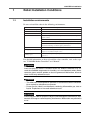
1-1
Installation environments
Be sure to install the robot in the following environments.
Items
Specifications
Allowable ambient temperature 0 to 40°C
Allowable ambient humidity
35 to 85% RH (non condensation)
Altitude
0 to 1000 meters above sea level
Ambient environments
Avoid installing near water, cutting water, oil, dust, metallic chips and
organic solvent.
Avoid installation near corrosive gas and corrosive materials.
Avoid installation in atmosphere containing inflammable gas, dust or liquid.
Avoid installation near objects causing electromagnetic interference,
electrostatic discharge or radio frequency interference.
Vibration
Do not subject to impacts or vibrations.
Air supply pressure, etc.
Below 0.58MPa (6.0kgf/cm2); clean dry air not containing deteriorated
compressor oil; filtration 40µm or less
Working space
Allow sufficient space margin to perform jobs (teaching, inspection,
repair, etc.)
For detailed information on how to install the robot controller, refer to the separate "YAMAHA Robot Controller User's Manual".
WARNING
Avoid installing the robot in locations where the ambient conditions may exceed the allowable temperature or humidity, or in environments where water,
corrosive gases, metallic powder or dust are generated. Malfunction, failure or
short circuits may otherwise result.
WARNING
• This robot was not designed for operation in environments where inflammable or explosive substances are present.
• Do not use the robot in environments containing inflammable gas, dust or
liquids. Explosions or fire could otherwise result.
WARNING
Avoid using the robot in locations subject to electromagnetic interference, electrostatic discharge or radio frequency interference. Malfunction may otherwise
occur.
3-1
CHAPTER 3 Installation
WARNING
Do not operate the robot in locations subject to strong vibrations. The robot
installation bolts might work loose and the robot topple over. The bolts on the
robot body itself might also loosen, causing parts to fall off, etc.
! CAUTION
A positioning error may occur if the machine harness, user signal cables or air
tubes have deteriorated due to improper installation environment.
3-2
CHAPTER 3 Installation
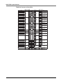
1-2
Installation base
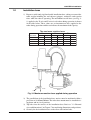
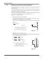
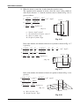
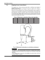
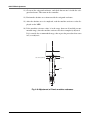
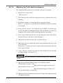
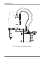
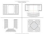
1) Prepare a sufficiently rigid and stable installation base, taking account of the
robot weight including the end effector (gripper), workpiece and reaction
force while the robot is operating. The maximum reaction force (see Fig. 31) applied to the X-axis and Z-axis of each robot during operation is shown
in the table below. These values are an instantaneous force applied to the
robot during operation and do not indicate the maximum load capacity.
The maximum reaction force
FXmax
MXmax
Robot Mode
N
kgf
YK120X
23
YK150X
27
YK180X
YK220X
FZmax
Nm
kgfm
N
kgf
2.3
3.3
0.34
6.7
0.7
2.7
3.3
0.34
6.7
0.7
196
20
18
1.8
6.7
0.7
157
16
18
1.8
6.7
0.7
Fxmax
Fzmax
Mxmax
Load
Fig. 3.1 Maximum reaction force applied during operation
2) The parallelism of the installation base surface must be machined within a
precision of ±0.05mm/500mm. The robot base mount must be installed facing down and in a level position.
3) Tap holes into the surface of the installation base. Refer to "1-2 External
view and dimensions" in Chapter 7 for machining dimensions and positions.
4) Securely fix the installation base on the floor with anchor bolts.
3-3
CHAPTER 3 Installation
WARNING
Do not place the robot on a moving installation base. Excessive loads will be
applied to the robot arm by movement of the installation base, resulting in damage to the robot.
! CAUTION
The manipulator positioning might decrease if the installation surface precision
is insufficient.
! CAUTION
If the installation base is not sufficiently rigid and stable or a thin metallic plate
is attached to the installation base, vibration (resonance) may occur during
operation, causing detrimental effects on the manipulator work.
3-4
CHAPTER 3 Installation
2
Installation
2-1
Unpacking
WARNING
The robot and controller are heavy. Take sufficient care not to drop them during
moving or unpacking as this may damage the equipment or cause bodily injury.
! CAUTION
When moving the robot or controller by equipment such as a forklift that require
a license, only properly qualified personnel may operate it. The equipment and
tools used for moving the robot should be serviced daily.
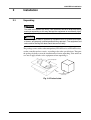
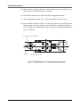
The package comes with a robot manipulator (YK120X series or YK180X series),
a robot controller and accessories, according to the order specifications. Transport
the package by dolly to near the installation base before unpacking. Take sufficient
care not to apply shocks to the equipment when unpacking it.
Robot manipulator
Case
Robot controller and
accessories
Fig. 3-2 Packed state
3-5
CHAPTER 3 Installation
2-2
Checking the product
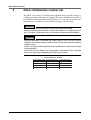
After unpacking, check the product configuration and conditions.
The following configurations are typical examples, so please check that the product is as specified in your order.
! CAUTION
If there is any damage due to transportation or insufficient parts, please notify
your YAMAHA sales office or dealer immediately.
Controller
Robot
: RCX142-T, RCX142
: YK120X, YK150X, YK180X, YK220X
Standard
Warning label ( × 1)
CD-ROM User's Manual
or
User's Manual
User wiring connector ( × 2)
User wiring pin ( × 20)
OP.3
OP.1
42
RCX1
MODEL.
NO.
IN JAPAN
MADE
TURED
N EQUIPMENT
MANUFAC
AUTOMATIO
FACTORY
SER.
ION
CAUT
MPB
MOTOR
PWR
CTION
INSTRU
READ L
MANUA
SRV
ERR
XM
ROB
I/O
T
BAT
XY
XY
YM
COM
ZR
A
X
Z
B
Y
R
Rotation direction labels ( × 1)
N
RGE
ROB
I/O
OP.4
OP.2
P
N
ZR
.DIO
STD
ZM
ETY
SAF
ACIN
L
N
RM
Robot manipulator
YK-120X series
(YK120X, YK150X)
YK-180X series
(YK180X, YK220X)
0V~
-23
200 60HzVA
50- 500
X.2
MA
RCX142-T controller and accessories (YK120X, YK150X)
RCX142 controller and accessories (YK180X, YK220X)
Option
MPB programming unit, etc.
Refer to the "YAMAHA Robot Controller User's Manual" for details on the controller accessories and options.
Fig. 3-3 Product configurations
3-6
CHAPTER 3 Installation
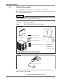
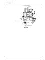
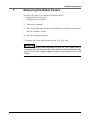
2-3
Moving the robot
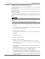
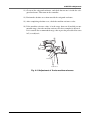
1) Fold in the arm and wind the robot cable as shown in Fig. 3-4.
2) The robot must be carried by two workers. One worker must hold the support
sections shown in the drawing with both hands, and the other worker must
carry the robot cable. Place the robot on the installation base, and temporarily tighten with the bolts. (Refer to section "2-4 Installing the robot" for the
bolt tightening torque values.)
Robot cable
Support part
Support part
Bolt installation hole
Fig. 3-4
! CAUTION
If the robot is transported long distances by truck while mounted on an installation
base or packed in a case other than the dedicated carton box in which the robot
was shipped, the bolts installing the robot or the bolts on the robot body itself
might come loose due to vibration. The robot might then topple over or the
parts fall off.
When transporting the robot long distances, use the dedicated case in which
the robot was shipped from our factory.
3-7
CHAPTER 3 Installation
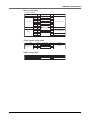
2-4
Installing the robot
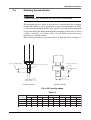
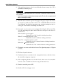
Install the robot securely with the four hex socket head bolts as shown in Fig. 35.
WARNING
Be sure to use the specified type and number of bolts, and securely tighten
them to the correct torque. If the bolts are not tightened correctly, the robot may
cause positioning errors or fall over during operation, causing a serious accident.
Tightening torque
Robot Mode
Bolts Used
YK120X, YK150X
M3
2.0Nm (20kgfcm)
YK180X, YK220X
M6
15.3Nm (156kgfcm)
Tightening torque
Installation base
Hex socket head bolt
Fig. 3-5 Installing the robot
3-8
CHAPTER 3 Installation
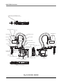
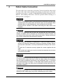
3
Protective Bonding
Be sure to ground the robot and controller to prevent electrical shock.
WARNING
Turn off the controller before grounding the robot.
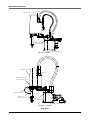
The robot must be grounded as follows:
1) Provide a terminal marked "PE" for the protective conductor of the entire
system and connect it to an external protective conductor. In addition, securely connect the ground terminal on the robot pedestal to the same protective conductor. (See Fig. 3-6.)
(Symbol 417-IEC-5019)
2) When the end effector uses an electrical device which, if it malfunctions,
might make contact with the power supply, the user must provide proper
grounding on his own responsibility. The YK-X series robots do not have a
ground terminal for this purpose.
3) For details on protective bonding on the robot body to comply with CE marking, follow the instructions on protective bonding explained in the "YAMAHA
Robot Controller User's Manual" or "CE marking manual".
4) Use a ground cable with a conductor wire cross section of at least 2.0mm2
and a length within 1 meter.
3-9
CHAPTER 3 Installation
Ground symbol
Ground symbol
M3 Ground terminal
M3 Ground terminal
YK120X, YK150X
YK180X, YK220X
Fig. 3-6 Ground terminal
3-10
CHAPTER 3 Installation
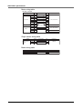
4
Robot Cable Connection
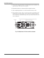
The robot cable is pre-connected to each robot. Correctly install the other end of
the robot cable to the robot controller. For details on connections to the robot
controller, refer to Fig. 3-7 and the "YAMAHA RCX142 Robot Controller User's
Manual". After making connections, check the operation while referring to "6
Trial operation" in Chapter 1.
WARNING
• Before connecting the cables, check that there are no bends or breaks in the
connector pins of the robot cable and that the cables are not damaged. Bent
or broken pins or cable damage may cause malfunction of the robot.
• Ensure that the controller is off before connecting the robot cable to the
controller.
WARNING
The MOTOR connectors XM and ZM, and YM and RM each have identical
shapes. In addition, the PI connectors XY and ZR have identical shapes. Do
not confuse these connectors when making connections. Wrong connections
may result in malfunction and hazardous situations.
WARNING
• If the connector installation is inadequate or if there are contact failures in
the pins, the robot may malfunction causing a hazardous situation. Reconfirm that each connector is securely installed before turning on the controller.
• To attach the PI connector securely, tighten the screws supplied with the
robot.
• Take caution not to apply an excessive load to the connectors due to stress
or tension on the cables.
WARNING
Lay out the cables so that they do not obstruct the movement of the manipulator. Determine the robot work area in which the robot cables will not interfere
with the load or workpiece picked up by the manipulator. (See "1-2 External
view and dimensions" in Chapter 7.) If the robot cables interfere with the movable parts of the robot, the cables may be damaged causing malfunction and
hazardous situations.
WARNING
Lay out the robot cables so as to keep the operator or any other person from
tripping on them. Bodily injury may result if someone trips on the cables.
3-11
CHAPTER 3 Installation
WARNING
For the YK120X series robots (YK120X, YK150X), always use the RCX142-T
controller that is designed to provide 24V output. The model name "RCX142-T"
is shown on the serial number label (see Fig. 2-5). Do not connect other robot
controllers to the YK120X series robots. If operated from a controller other than
the RCX142-T, the robot's motors may be damaged.
Controller side connector
Robot side connector
Robot cable
XM
XM
YM
YM
ZM
ZM
RM
RM
XY
XY
ZR
ZR
Fig. 3-7 Robot cable connections
3-12
RCX142-T
CHAPTER 3 Installation
5
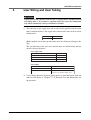
User Wiring and User Tubing
WARNING
Always turn off the controller and shut off air supply before attempting wiring
and piping work. If air or power is supplied during this work, the manipulator
may move erroneously causing a hazardous situation.
1) The robot has a user signal wire and air tube laid in parallel with the robot
body's machine harness. The signal wires and air tubes that can be used are
shown below.
User wiring
User tubing
6 wires
φ3, 2 tubes
(Robot models for custom specifications may have different wiring or tubing.)
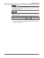
The specifications of the user wires and air tubes are shown below. Always
observe the specifications.
User signal cable
Rated voltage
30V
Allowable current
1.5A
Nominal cross-section area of conductor
0.1mm2
Shield
No
User Tubing
Maximum pressure
0.58MPa (6Kgf/cm2)
Outer diameter × inner diameter
φ3×φ1.5
Fluid
Dry clean air not containing deteriorated
compressor oil; filtration 40µm or less
2) User wiring connectors and user piping joints are provided on the arm side
and base side. Refer to "Chapter 7, 1-2. External view and dimensions" for
the positions.
3-13
CHAPTER 3 Installation
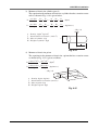
3) Signal wiring connections in the machine harness
Connector pins 1 to 6 can be used.
Signal
User signal line
Connector No Connection No Connector
1
1
2
2
IO
IO
3
3
(Arm side) 4
4 (Base side)
5
5
6
6
Color
Orange
Orange
Orange
Orange
Orange
Orange
(Robots models with non-standard specifications
may have different wiring colors.)
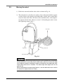
4) Crimp the user wiring to the connector (supplied) using a crimping tool (J.S.T.
Mfg Co., Ltd. YC12) or solder as shown in Fig. 3-8.
Lock mechanism
Cable to be
prepared by user
Connector (supplied)
Robot side connector
pin
Fig. 3-8
WARNING
Securely fix the connector (supplied) to the robot's connector using the lock
mechanism attached with the housing (See Fig. 3-8). The operation could malfunction if the connector dislocates.
WARNING
Do not utilize the machine harness, user signal wires or air tubes of the robot to
fasten any cable or tube prepared by the user, as this may break the robot
harness wires or user signal wires causing malfunction of the robot. This will
also result in poor positioning accuracy.
WARNING
Make sure that user wiring and piping connected with the user wiring connector
and user wiring joint do not interfere with the robot, get wound around the robot
or led around when the robot moves. The wiring and piping could be damaged
and result in malfunctioning.
3-14
CHAPTER 3 Installation
WARNING
Arrange the user wiring and piping installed with the user wiring connector and
user piping joint not to pose hazards for the operators. The operators could trip
on these parts and be injured.
! CAUTION
Always use the supplied connectors and pins. Contact faults could occur if
other types are used.
Arm side and base side connector (supplied)
SM Connector SMR-6V-B
Pin
BYM-001T-0.6
or SYM-001T-P0.6
Manufacture
J.S.T. Mfg Co., Ltd.
5) To check the operation and signal transmission between the end effector and
the controller or peripheral equipment after making connections, refer to "6.
Trial operation" in Chapter 1.
3-15
CHAPTER 3 Installation
6
Connecting a suction hose (YK120XC, YK150XC)
WARNING
Always turn off the robot controller and shut off air supply before connecting a
suction hose.
Clean room models have two suction couplers (φ6) on the rear of the manipulator
base for air suction from the base interior and from the X, Y, R axis joints, and
also have one bellows type suction coupler (φ3) for the R-axis.
The required degree of cleanliness can be maintained by sucking air through
these suction couplers.
For the suction amount versus degree of cleanliness, see "1-1 Basic specifications"
in chapter 7. For the location of the suction couplers, see "1-2 External view and
dimensions" in chapter 7.
WARNING
Lay out the suction hoses so as to keep the operator or any other person from
tripping on them. Bodily injury may result if someone trips on the hoses.
! CAUTION
Carefully connect the suction hoses to the suction couplers so that they do not
obstruct the movement of the robot manipulator.
3-16
CHAPTER 3 Installation
7
Attaching The End Effector
7-1
R-axis tolerable moment of inertia and acceleration coefficient
1) The moment of inertia of a load (end effector and workpiece) that can be
attached to the R-axis is limited by the strength of the robot drive unit and
residual vibration during positioning. It is therefore necessary to reduce the
acceleration coefficient in accordance with the moment of inertia.
2) The R-axis tolerable moment of inertia and the acceleration coefficient versus R-axis moment of inertia for each robot model are shown in Fig. 3-9,
Fig. 3-10 and Fig. 3-11 on the subsequent pages. The symbols AX, AY, and AR
in each figure respectively indicate the acceleration coefficients of the Xaxis, Y-axis and R-axis. The symbol IR (JR) is the moment of inertia of the
load around the R-axis and m is the tip mass.
Example: YK120X
Assume that the mass of the load installed to the R-axis is 0.15kg and the
moment of inertia around the R-axis is 0.0005kgm2 (0.005kgfcmsec2). When
the tip mass parameter is set to 0.2kg, the robot can be operated by reducing
the X, Y and R-axis acceleration coefficients to 50%, as can be seen from
Fig. 3-9.
Be sure to select an optimum tip mass and acceleration coefficient parameters that meet the mass of the load and moment of inertia before using the
robot.
To make settings for the tip mass and acceleration coefficient, refer to the
separate "YAMAHA Robot Controller User's Manual".
3) Methods for calculating the moment of inertia of the load are shown in Section 6-2, however, it is not easy to precisely figure out these values.
If a calculated value smaller than the actual moment of inertia is set, residual
vibrations may occur. If this happens, reduce the acceleration coefficient parameter even further.
! CAUTION
The robot must be operated with correct tolerable moment of inertia and acceleration coefficients according to the manipulator tip mass and moment of inertia. If this is not observed, premature end to the life of the drive units, damage to
the robot parts or residual vibration during positioning may result.
3-17
CHAPTER 3 Installation
! CAUTION
Depending on the Z-axis position, vibration may occur when the X, Y or R-axis
moves. If this happens, reduce the X, Y or R-axis acceleration to an appropriate level.
! CAUTION
If the moment of inertia is too large, vibration may occur on the Z-axis depending on its operation position. If this happens, reduce the Z-axis acceleration to
an approriate level.
3-18
CHAPTER 3 Installation
7-1-1
Acceleration coefficient vs. moment of inertia (YK120X)
AX, AY, AR (%)
100
0.00025 (0.0025)
80
60
40
20
0
0
0.0005
0.005
0.0010
0.010
0.0015
0.015
0.0020 Ir (kgm2)
0.020 Jr (kgfcmsec2)
0.0015
0.015
0.0020 Ir (kgm2)
0.020 Jr (kgfcmsec2)
W=0.1kg
AX, AY, AR (%)
100
0.0008 (0.00008)
80
60
40
20
0
0
0.0005
0.005
0.0010
0.010
W=0.2kg
AX, AY, AR (%)
100
0.0005 (0.00005)
80
60
40
20
0.0011 (0.011)
0
0
0.0005
0.005
0.0010
0.010
W=0.3kg
3-19
0.0015
0.015
0.0020 Ir (kgm2)
0.020 Jr (kgfcmsec2)
CHAPTER 3 Installation
AX, AY, AR (%)
100
0.00002 (0.0002)
80
60
40
20
0
0
0.0005
0.005
0.0010
0.010
0.0015
0.015
0.0020 Ir (kgm2)
0.020 Jr (kgfcmsec2)
0.0015
0.015
0.0020 Ir (kgm2)
0.020 Jr (kgfcmsec2)
W=0.4kg
AX, AY, AR (%)
100
0.00002 (0.0002)
80
60
40
20
0
0
0.0005
0.005
0.0010
0.010
W=0.5kg
Fig. 3-9
3-20
CHAPTER 3 Installation
7-1-2
Acceleration coefficient vs. moment of inertia (YK150X)
AX, AY, AR (%)
100
0.00004 (0.0004)
80
60
40
20
0.00025(0.0025)
0
0
0.0005
0.005
0.0010
0.010
0.0015
0.015
0.0020 Ir (kgm2)
0.020 Jr (kgfcmsec2)
0.0015
0.015
0.0020 Ir (kgm2)
0.020 Jr (kgfcmsec2)
W=0.1kg
AX, AY, AR (%)
100
0.00018 (0.0018)
80
60
40
20
0
0
0.0005
0.005
0.0010
0.010
W=0.2kg
AX, AY, AR (%)
100
80
60
40
20
0.0011 (0.011)
0
0
0.0005
0.005
0.0010
0.010
W=0.3kg
3-21
0.0015
0.015
0.0020 Ir (kgm2)
0.020 Jr (kgfcmsec2)
CHAPTER 3 Installation
AX, AY, AR (%)
100
0.00016 (0.0016)
80
60
40
20
0
0
0.0005
0.005
0.0010
0.010
0.0015
0.015
0.0020 Ir (kgm2)
0.020 Jr (kgfcmsec2)
0.0015
0.015
0.0020 Ir (kgm2)
0.020 Jr (kgfcmsec2)
W=0.4kg
AX, AY, AR (%)
100
0.00005 (0.0005)
80
60
40
20
0
0
0.0005
0.005
0.0010
0.010
W=0.5kg
Fig. 3-10
3-22
CHAPTER 3 Installation
7-1-3
Acceleration coefficient vs. moment of inertia (YK180X, YK220X)
AX, AY, AR (%)
100
0.0005 (0.005)
80
60
40
20
0
0.005
0.05
0
0.01 Ir (kgm2)
0.1 Jr (kgfcmsec2)
W=0.1 to 0.4kg
AX, AY, AR (%)
100
0.0005 (0.005)
80
60
40
20
0
0.005
0.05
0
0.01 Ir (kgm2)
0.1 Jr (kgfcmsec2)
W=0.5 to 0.8kg
AX, AY, AR (%)
100
0.0005 (0.005)
80
60
40
20
0
0.005
0.05
0
W=0.9, 1.0kg
Fig. 3-11
3-23
0.01 Ir (kgm2)
0.1 Jr (kgfcmsec2)
CHAPTER 3 Installation
7-2
Equation for moment of inertia calculation
Usually the R axis load is not a simple form, and the calculation of the moment of
inertia is not easy.
As a method, the load is replaced with several factors that resemble a simple form
for which the moment of inertia can be calculated. The total of the moment of
inertia for these factors is then obtained.
The objects and equations often used for the calculation of the moment of inertia
are shown below. Incidentally, there is the following relation:
J (kgfcmsec2) = I (kgm2) × 10.2.
1) Moment of inertia for material particle
The equation for the moment of inertia for a material particle that has a rotation center such as shown in Fig. 3-12 is as follows:
This is used as an approximate equation when x is larger than the object size.
I= mx2 (kgm2)
2
J= Wx (kgfcmsec2)
g
... (Eq. 3.1)
x
g : Gravitational acceleration (cm/sec2)
m : Mass of material particle (kg)
W : Weight of material particle (kgf)
Fig. 3-12
2) Moment of inertia for cylinder (part 1)
The equation for the moment of inertia for a cylinder that has a rotation center
such as shown in Fig. 3-13 is given below.
I=
J=
2
ρπ D 4 h
= mD (kgm2)
32
8
2
ρπ D 4 h
= WD (kgfcmsec2)
32g
8g
... (Eq. 3.2)
h
ρ : Density (kg/m , kg/cm )
g : Gravitational acceleration (cm/sec2)
m : Mass of cylinder (kg)
W : Weight of cylinder (kgf)
3
3
D
Fig. 3-13
3-24
CHAPTER 3 Installation
3) Moment of inertia for cylinder (part 2)
The equation for the moment of inertia for a cylinder that has a rotation center
such as shown in Fig. 3-14 is given below.
I=
J=
D2
D2
h2
h2
ρπ D 2 h
) = m (
) (kgm2)
(
+
+
4
4
3
3
16
4
D2
D2
h2
h2
ρπ D 2 h
) = W (
) (kgfcmsec2)
(
+
+
4
4
3
3
16g
4g
... (Eq. 3.3)
ρ : Density (kg/m3, kg/cm3)
g : Gravitational acceleration (cm/sec2)
m : Mass of cylinder (kg)
W : Weight of cylinder (kgf)
D
h
2
h
Fig. 3-14
4) Moment of inertia for prism
The equation for the moment of inertia for a prism that has a rotation center
as shown in Fig. 3-15 is given as follows.
I=
ρ abc(a 2 +b 2 ) m(a2 +b 2 )
=
(kgm2)
12
12
J=
ρ abc(a 2 +b 2 ) W(a2 +b 2 )
=
(kgfcmsec2)
12g
12g
... (Eq. 3.4)
c
1/2a
b
ρ : Density (kg/m3, kg/cm3)
g : Gravitational acceleration (cm/sec2)
m : Mass of prism (kg)
W : Weight of prism (kgf)
a
Fig. 3-15
3-25
CHAPTER 3 Installation
5) When the object's center line is offset from the rotation center.
The equation for the moment of inertia, when the center of the cylinder is
offset by the distance "x" from the rotation center as shown in Fig. 3-16, is
given as follows.
2
ρπD 4 h
ρπD 2 hx2
= mD + mx2 (kgm2)
+
32
4
8
ρπD 4 h
ρπD 2 hx 2
J=
+
32g
4g
I=
2
= WD + Wx
g
8g
Center line
Rotation center
2
(kgfcmsec2)
h
... (Eq. 3.5)
ρ : Density (kg/m3, kg/cm3)
g : Gravitational acceleration (cm/sec2)
m : Mass of cylinder (kg)
W : Weight of cylinder (kgf)
D
x
Fig. 3-16
In the same manner, the moment of inertia of a cylinder as shown in Fig. 3-17
is given by
D2
h2
ρπ D 2h
ρπ D 2 h x 2
D2
m
h2
)+
(
+
) + mx2 (kgm2)
(
=
+
4
4
3
4
16
4
3
D2
h2
ρπ D 2 h
ρπ D 2h x 2
)+
(
J=
+
4
3
4g
16g
Cneter line
2
2
2
D
h
W
Wx
2
) +
(
=
+
(kgfcmsec )
g
4g
4
3
I=
... (Eq. 3.6)
D
x
h
Fig. 3-17
In the same manner, the moment of inertia of a prism as shown in Fig. 3-18 is
given by
ρabc(a2 + b 2 )
m(a2 +b 2 )
+ ρabcx2=
+ mx2 (kgm2)
12
12
ρabc(a 2 + b2 )
ρabcx2
J=
+
12g
g
I=
=
2
W(a 2 + b2 )
+ Wx (kgfcmsec2)
12g
g
... (Eq. 3.7)
Center line
c
x
b
a
m : Mass of prism (kg)
W : Weight of prism (kgf)
Fig. 3-18
3-26
CHAPTER 3 Installation
7-3
Example of moment of inertia calculation
Let's discuss an example in which the chuck and workpiece are at a position
offset by 10cm from the R-axis by a stay, as shown in Fig. 3-19.
The moment of inertia is calculated with the following three factors, assuming
that the load material is steel and its density ρ is 0.0078kg/cm3.
R-axis
2cm
Stay
2cm
2cm
1cm
10cm
4cm
1cm
6cm
Chuck
Workpiece
4cm
2cm
Fig. 3-19
1) Moment of inertia of the stay
From Fig. 3-20, the weight of the
stay (Ws) is given as follows:
Center line
R-axis
Ws = ρabc = 0.0078 × 12 × 2 × 2
= 0.37 (kgf)
2cm
5cm
2cm
12cm
Fig. 3-20
The moment of inertia of the stay (Js) is then calculated from Eq. 3-7.
2
2
0.37 × 52
Js = 0.37 × (12 +2 ) +
= 0.014 (kgfcmsec2)
12 × 980
980
3-27
CHAPTER 3 Installation
2) Moment of inertia of the chuck
When the chuck form resembles that shown in Fig. 3-21,
the weight of the chuck (Wc)
is
Wc = 0.0078 × 2 × 4 × 6
6cm
= 0.37 (kgf)
The moment of inertia of the
chuck (Jc) is then calculated
from Eq. 3-7.
10cm
2cm
R-axis
4cm
0.37 × (22+42)
12 × 980
0.37 × 10²
+
980
= 0.038 (kgfcmsec2)
Jc =
Fig. 3-21
3) Moment of inertia of workpiece
10cm
When the workpiece form
resembles that shown in Fig.
3-22, the weight of the
workpiece (Ww) is
ρπD2h 0.0078π × 22 × 4
=
4
4
= 0.098 (kgf)
Ww =
4cm
The moment of inertia of the
workpiece (Jw) is then calculated from Eq. 3-5.
2cm
0.097 × 22 0.097 × 10²
+
8 × 980
980
= 0.010 (kgfcmsec2)
Jw=
Fig. 3-22
4) Total weight
The total weight (W) is calculated as follows:
W = Ws + Wc + Ww = 0.84 (kgf)
5) Total moment of inertia
The total moment of inertia (J) is then obtained as follows:
J = Js + Jc + Jw = 0.062 (kgfcmsec2)
3-28
R-axis
CHAPTER 3 Installation
7-4
Attaching the end effector
WARNING
Before attaching the end effector, be sure to turn off the controller.
The manipulator part to which an end effector is attached must have adequate
strength and rigidity, as well as gripping force to prevent positioning errors. Table
3-1 shows the maximum load that can be applied to the end effector attachment
of each robot model. Recommended methods for attaching end effectors are shown
in Table 3-2 and Fig. 3-25. Refer to Fig. 3-23 for details on the end effector
attachment of each robot model.
When checking end effector operation, refer to "6 Trial Operation" in Chapter 1.
User tool installation range
Never loosen this bolt.
Retaining ring to set the user tool
15
10
User tool installation range
φ10 h7
0
φ6 -0.012
YK120X, YK150X
0
-0.015
YK180X, YK220X
Fig. 3-23 Z-axis tip shape
Table 3-1
FXYmax
FZmax
FRmax
MRmax
Mmax
Robot Mode
N
kgf
N
kgf
N
kgf
Nm
kgfm
Nm
kgfm
YK120X
27
2.8
6.7
0.7
9.8
1.0
0.5
0.05
0.4
0.04
YK150X
27
2.8
6.7
0.7
12
1.3
0.5
0.05
0.4
0.04
YK180X
27
2.8
6.7
0.7
15.7
1.6
4.5
0.46
0.9
0.09
YK220X
30
3.1
6.7
0.7
18.6
1.9
4.5
0.46
0.9
0.09
3-29
CHAPTER 3 Installation
End effector
Stay
Frmax
Mmax
Mrmax
Fxymax
Fzmax
Fig. 3-24 Maximum load applied to end effector attachment
Table 3-2
Robot Mode
Bolts Used Number of bolts
Tightening torque
Nm
kgfcm
diameter(mm)
YK120X, YK150X M3 or lager
2 or more
2.0
20
6
YK180X, YK220X M4 or lager
2 or more
4.5
46
10
Hole diameter
Bolt
Slot
Spline shaft
End effector or stay
Fig. 3-25
3-30
+0.012
0
+0.015
0
CHAPTER 3 Installation
WARNING
The end effector attachment must have adequate strength to withstand the
loads listed in Table 3-1. If too weak, the attachment may break during robot
operation and fragments fly off causing accidents or injuries.
WARNING
The end effector attachment must have sufficient rigidity versus the loads listed
in Table 3-1. If this rigidity is inadequate, the end effector may vibrate during
robot operation causing bad effects on the manipulator operation.
WARNING
• When the end effector is attached by slot clamping, always observe the conditions listed in Table 3-2. If these are ignored, the end effector may come
loose and fly off during robot operation, resulting in an accident or injury.
• In cases where other attachment methods are used, be sure that the end
effector will not come off when the loads listed in Table 3-1 are applied.
! CAUTION
The YK120X series (YK120X, YK150X) and YK180X series (YK180X, YK220X)
is designed to be compact, so the joints could be damaged if excessive force is
applied, for example, during installation of an end effector.
Make sure that excessive force is not applied to the joints.
YK120X, YK150X
Axis
Tolerable radial load Tolerable thrust load Tolerable moment load
Tolerable torque
X-axis
100N (10.2kgf)
100N (10.2kgf)
1.5Nm (15.3kgfcm)
1.7Nm (17.3kgfcm)
Y-axis
45N (4.6kgf)
45N (4.6kgf)
0.45Nm (4.6kgfcm)
0.5Nm (5.1kgfcm)
R-axis
45N (4.6kgf)
45N (4.6kgf)
0.45Nm (4.6kgfcm)
0.3Nm (3.1kgfcm)
YK180X, YK220X
Axis
Tolerable radial load Tolerable thrust load Tolerable moment load
Tolerable torque
X-axis
275N (28.1kgf)
900N (91.8kgf)
6.0Nm (61.2kgfcm)
9.0Nm (91.8kgfcm)
Y-axis
150N (15.3kgf)
600N (61.2kgf)
3.3Nm (33.7kgfcm)
4.0Nm (40.8kgfcm)
R-axis
150N (15.3kgf)
600N (61.2kgf)
3.3Nm (33.7kgfcm)
2.2Nm (22.4kgfcm)
3-31
CHAPTER 3 Installation
7-5
Gripping force of end effector
The gripping force of the end effector must have a sufficient extra margin of
strength versus the workpiece weight and reaction force applied to the workpiece
during robot operation.
The reaction force applied to the workpiece during operation can be calculated
from the acceleration applied to the end effector attachment. The maximum acceleration on the end effector attachment of each robot model is listed in the table
below. When the workpiece position is offset to the end effector attachment, the
accelerations Amax and AXYmax become larger by an amount equal to the offset
versus the arm length. When the R-axis rotates during operation, this acceleration
ARmax must be taken into account.
Table 3-3 Maximum acceleration during robot operation
Robot Model
Amax(m/sec2)
AXYmax(m/sec2)
Azmax(m/sec2)
ARmax(rad/sec2)
YK120X
20
8.4
23
267
YK150X
25
11
16
267
YK180X
50
16
16
767
YK220X
61
19
16
767
ARmax
Amax
AXYmax
Azmax
Fig. 3-26 Maximum acceleration on end effector attachment
WARNING
The gripping force of the end effector must have a sufficient extra margin of
strength to prevent the workpiece from coming loose and flying off during robot
operation.
If the gripping force is too weak, the workpiece may come loose and fly off
causing accidents or injuries.
3-32
CHAPTER 3 Installation
8
Working Envelope and Mechanical Stopper
Positions for Maximum Working Envelope
Working envelope and mechanical stopper positions for the maximum working
envelope of each robot are shown in "1-2 External view and dimensions" in Chapter
7.
An example using the YK120X is described below. (Refer to Fig. 7-1.) Other
robot models are the same.
1) X and Y axes
Do not attempt operation outside the working envelope. The working envelope described in this manual is an area with the robot frontal reference.
2) Z-axis
Do not attempt work outside the working envelope. In particular, do not attempt work in the area between the working envelope and mechanical stopper position. Mechanical stoppers are installed at both the upper and lower
ends of the movement range.
WARNING
The robot cable, user wiring or tubing may be damaged if the robot load interferes with them resulting in hazardous robot malfunctions. Do not operate at
points where the load may interfere with the robot cable, user wiring or tubing.
3) R-axis
The R-axis has no mechanical stoppers.
! CAUTION
Since the R-axis has no mechanical stoppers, make certain that the end effector wiring and tubing do not become entangled during operation.
3-33
MEMO
3-34
CHAPTER 4
Adjustment
1
Overview ..................................................................................................4-1
2
Safety Precautions ..................................................................................4-1
3
Adjusting the origin ..................................................................................4-2
3-1
Absolute reset method ......................................................................................... 4-3
3-1-1
YK120X series (YK120X, YK150X) ........................................................................ 4-3
3-1-1-1
3-1-1-2
3-1-1-3
3-1-2
YK180X series (YK180X, YK220X) ........................................................................ 4-7
3-1-2-1
3-1-2-2
3-1-2-3
3-2
3-3
3-4
Sensor method (R-axis) ........................................................................................ 4-3
Stroke end method (X-axis, Y-axis) ...................................................................... 4-4
Stroke end method (Z-axis) .................................................................................. 4-6
Sensor method (R-axis) ........................................................................................ 4-7
Sensor method (X-axis, Y-axis) ............................................................................ 4-8
Stroke end method (Z-axis) .................................................................................. 4-9
Machine reference .............................................................................................. 4-10
Absolute reset procedures .................................................................................. 4-11
3-3-1
Sensor method (R-axis) ....................................................................................... 4-11
3-3-2
Stroke end method (X and Y axes of YK120X, YK150X) ..................................... 4-13
3-3-3
Stroke end method (Z-axis) .................................................................................. 4-15
3-3-4
Sensor method (X and Y axes of YK180X, YK220X) ........................................... 4-16
Adjusting the machine reference ........................................................................ 4-18
3-4-1
YK120X series (YK120X, YK150X) ...................................................................... 4-19
3-4-1-1
3-4-1-2
3-4-1-3
3-4-1-4
3-4-1-5
3-4-2
Adjusting the R-axis machine reference (YK120X, YK150X) ............................. 4-19
Adjusting the R-axis machine reference (YK120XC, YK150XC) ........................ 4-21
Adjusting the X-axis machine reference ............................................................. 4-23
Adjusting the Y-axis machine reference .............................................................. 4-25
Adjusting the Z-axis machine reference ............................................................. 4-27
YK180X series (YK180X, YK220X) ...................................................................... 4-30
3-4-2-1
3-4-2-2
3-4-2-3
3-4-2-4
Adjusting the R-axis machine reference (YK180X, YK220X) ............................. 4-30
Adjusting the X-axis machine reference ............................................................. 4-32
Adjusting the Y-axis machine reference .............................................................. 4-34
Adjusting the Z-axis machine reference ............................................................. 4-36
4
Setting the Soft Limits ............................................................................4-39
5
Setting the Standard Coordinates .........................................................4-42
6
Affixing Stickers for Movement Directions and Axis Names ..................4-43
7
Removing the Robot Covers .................................................................4-45
MEMO
CHAPTER 4 Adjustment
1
Overview
YAMAHA robots have been completely adjusted at the factory or by the sales
representative before shipment, including the origin position adjustment. If the
operating conditions are changed and the robot must be adjusted, then follow the
procedures described in this chapter.
2
Safety Precautions
(1) Read and understand the contents of this chapter completely before attempting to adjust the robot.
(2) Place a conspicuous sign indicating the robot is being adjusted, to prevent
others from touching the controller switch, programming unit or operation
panel.
(3) If a safeguard enclosure has not yet been provided right after installation of
the robot, rope off or chain off the movement area around the manipulator in
place of a safeguard enclosure, and observe the following points.
qUse stable posts which will not fall over easily.
wThe rope or chain should be easily visible by everyone around the robot.
ePlace a conspicuous sign prohibiting the operator or other personnel from
entering the movement area of the manipulator.
(4) To check operation after adjustment, refer to "6. Trial Operation" in Chapter 1.
4-1
CHAPTER 4 Adjustment
3
Adjusting the origin
All models of the YK120X series and YK180X series robots use an absolute type
position detector.
The origin position (zero pulse point) can be determined by absolute reset. Once
absolute reset is performed, you do not have to repeat absolute reset when turning
the power on next time.
However, absolute reset is required if any of the following cases occur. The robot
is shipped from the factory in condition "c" (below), so please perform absolute
reset after installing the robot. For more details on absolute reset, refer to "Absolute
Reset" in Chapter 4 of the "YAMAHA Robot Controller User's Manual".
a. Absolute-related error occurred on the axis.
b. Power drop was detected in the absolute battery for the driver installed
inside the robot controller.
c. Cable connecting the robot unit to the controller was disconnected.
(This is the status when shipped from the factory.)
d. Robot generation was changed.
e. Parameters were initialized.
f. Axis parameters "Origin shift", "Origin method", "Origin direction" or
"Motor direction" were changed.
g. Motor was replaced. (Motor wiring connector was removed.)
h. Data in the ALL data file (extension: ALL) or parameter file (extension:
PRM) was written into the controller by way of the RS-232C.
The following sections explain how to perform absolute reset.
! CAUTION
If any of the above cases occur after installing the robot, absolute reset must be
performed again. The robot must be moved to the origin position to perform
absolute reset. Select a robot position where the origin position will not interfere
with peripheral devices after setup is completed.
! CAUTION
After performing absolute reset, move the robot to a known point to check
whether the origin position is correctly set. When doing this check, move the
robot at the slowest possible speed.
The YK120X series and YK180X series absolute methods include the sensor
method and stroke end method.
The YK120X series uses the stroke end method for the X-axis, Y-axis and Z-axis,
and the sensor method for the R-axis.
The YK180X series uses the stroke end method for the Z-axis, and the sensor
method for the X-axis, Y-axis and R-axis.
4-2
CHAPTER 4 Adjustment
3-1
Absolute reset method
3-1-1
YK120X series (YK120X, YK150X)
3-1-1-1
Sensor method (R-axis)
In the sensor method, the target axis is automatically operated for the absolute
reset, and the absolute reset is performed at the position where the proximity
sensor provided on the target axis detects the detection area (dog).
The absolute reset in the sensor method can be executed with the teaching pendant (MPB), RS-232C communication, and dedicated input.
WARNING
Serious injury might occur from physical contact with the robot during operation.
Never enter within the robot movement range during absolute reset.
! CAUTION
The origin cannot be detected in any axis which is not positioned on the plus
side from the origin (See Fig. 4-1.) before starting the return-to-origin operation. (Factory setting at shipment.)
In this case, press the STOP key to interrupt the return-to-origin operation,
move the target axis to the plus side of the origin, and reperform the origin
return operation.
If the return-to-origin operation is not stopped, the robot will continue moving
and could collide with the peripheral devices. The R-axis does not have a mechanical stopper, so the wiring and piping installed on the end effector could
become entangled.
R-axis dog
Plus side
Plus side
R-axis Sensor
R-axis
R-axis Sensor
R-axis
Minus side
Minus side
YK120X, YK150X
YK120XC, YK150XC
Fig. 4-1 View of R-axis from below
4-3
CHAPTER 4 Adjustment
3-1-1-2
Stroke end method (X-axis, Y-axis)
With the stroke end method, the X and Y-axes are pushed against the mechanical
stopper, and after the axis end is detected, absolute reset is performed from a
position slightly back from the axis end.
WARNING
Serious injury might occur from physical contact with the robot during operation.
Never enter within the robot movement range during absolute reset.
! CAUTION
Before starting return-to-origin operation, move the X-axis to a position on the
plus side from the origin position (See Fig. 4-2), and the Y-axis to a position on
the minus side, so that the robot is positioned in a right-handed system as
shown in Fig. 4-2.
When the return-to-origin operation starts, the X-axis will move to the minus
side and the Y-axis will move to the plus side. After pushing against the mechanical stopper, the axes will return slightly, and the return-to-origin will be
completed.
The X and Y-axes will move to the positions shown in Fig. 4-3 during return-toorigin, so make sure that the tool on the end, the robot and the peripheral
devices do not interfere. The maximum tolerable load radius (when load is cylindrical object) is shown in Fig. 4-3. If return-to-origin is performed with a load
larger than this radius installed on the R-axis, the base and load could interfere.
4-4
CHAPTER 4 Adjustment
Plus side
°
±4
3°
11
Plus side
13
9°
±
4°
Minus side
Minus side
Fig. 4-2 Default origin position (YK120X, YK150X, YK120XC, YK150XC)
1°
12
1°
12
7°
14
YK120X (YK120XC)
Fig. 4-3
)
)
3°
YK150X (YK150XC)
3°
4
(1
R38
Maximum
tolerable
load radius *1
4
(1
7°
14
R13
Maximum
tolerable
load radius
*1
*1 When load is cylindrical object
X and Y-axis maximum movement position during
X and Y-axis stopper origin position setting
4-5
CHAPTER 4 Adjustment
3-1-1-3
Stroke end method (Z-axis)
With this method, the Z-axis is pushed against the mechanical stopper, and after
the axis end is detected, absolute reset is performed from a position slightly back
from the axis end.
WARNING
Serious injury might occur from physical contact with the robot during operation.
Never enter within the robot movement range during absolute reset.
4-6
CHAPTER 4 Adjustment
3-1-2
YK180X series (YK180X, YK220X)
3-1-2-1
Sensor method (R-axis)
In the sensor method, the target axis is automatically operated for the absolute
reset, and the absolute reset is performed at the position where the proximity
sensor provided on the target axis detects the detection area (dog).
The absolute reset in the sensor method can be executed with the teaching pendant (MPB), RS-232C communication, and dedicated input.
WARNING
Serious injury might occur from physical contact with the robot during operation.
Never enter within the robot movement range during absolute reset.
! CAUTION
The origin cannot be detected in any axis which is not positioned on the plus
side from the origin (See Fig. 4-4.) before starting the return-to-origin operation. (Factory setting at shipment.)
In this case, press the STOP key to interrupt the return-to-origin operation,
move the target axis to the plus side of the origin, and reperform the origin
return operation.
If the return-to-origin operation is not stopped, the robot will continue moving
and could collide with the peripheral devices. The R-axis does not have a mechanical stopper, so the wiring and piping installed on the end effector could
become entangled.
R-axis Sensor
R-axis dog
M inu s
side
Plus side
Fig. 4-4
4-7
CHAPTER 4 Adjustment
3-1-2-2
Sensor method (X-axis, Y-axis)
WARNING
Serious injury might occur from physical contact with the robot during operation.
Never enter within the robot movement range during absolute reset.
! CAUTION
The origin cannot be detected in any axis which is not positioned on the plus
side from the origin (See Fig. 4-5.) before starting the return-to-origin operation. (Factory setting at shipment.)
In this case, press the STOP key to interrupt the return-to-origin operation,
move the target axis to the plus side of the origin, and reperform the origin
return operation.
If the return-to-origin operation is not stopped, the robot will continue moving
and could collide with the peripheral devices.
The X and Y-axes will move to the positions shown in Fig. 4-5 during return-toorigin, so make sure that the tool on the end, the robot and the peripheral
devices do not interfere. The maximum tolerable load radius (when load is cylindrical object) is shown in Fig. 4-5. If return-to-origin is performed with a load
larger than this radius installed on the R-axis, the base and load could interfere.
Since the X-axis arm first returns to the origin, the tool on the end might interfere
with the robot base (pedestal) if the Y-axis arm is near its origin.
X-axis origin is at 0°±5° with
respect to front of robot base
X-axis origin is at 0°±5° with
respect to front of robot base
Plus side
°
±5
3°
13
Minus side
Minus side
3°
13
Plus side
°
±5
R17
Maximum
tolerable
load radius *1
R19
Maximum
tolerable
load radius *1
Plus side
Plus side
Minus side
Minus side
YK220X
YK180X
*1 When load is cylindrical object
Fig. 4-5 Default origin position
4-8
CHAPTER 4 Adjustment
3-1-2-3
Stroke end method (Z-axis)
With this method, the Z-axis is pushed against the mechanical stopper, and after
the axis end is detected, absolute reset is performed from a position slightly back
from the axis end.
WARNING
Serious injury might occur from physical contact with the robot during operation.
Never enter within the robot movement range during absolute reset.
4-9
CHAPTER 4 Adjustment
3-2
Machine reference
The YK-X series position detector uses a resolver having one position that can
perform absolute reset in respect to one motor rotation.
When absolute reset is performed with the sensor method or stroke end method,
the origin position will be set to a position where it can be reset immediately after
the origin sensor reacts to the dog (where the origin signal is detected) or the
stroke end (mechanical stopper) is detected.
The machine reference means the position relationship between the position where
the robot detects the origin signal and the position where the absolute reset can be
performed soon after the origin signal detection. (See Fig. 4-6.) The machine
reference is expressed in the ratio of interval A to interval B shown in Fig. 4-6.
Interval A is the minimum distance between the positions where absolute reset
can be performed and interval B is the distance between the position where the
origin signal is detected and the position where absolute reset can be performed
soon after the origin signal detection.
The machine reference value is displayed on the optional MPB screen. (Unit: %)
Machine reference value = B/A × 100(%)
! CAUTION
It is necessary for the machine reference to be adjusted in a specified range in
order to keep the repeatability precision of the absolute reset position. (Factoryadjusted at shipment.)
Refer to "Chapter 4, 3-4 Adjusting the machine reference" for the machine reference adjustment method .
Recommended machine reference value: 40 to 60% (26 to 74% only for Z-axis)
Machine reference
Origin signal detection
ON
OFF
Origin signal
Resolver
A
B
One motor revolution
Positions where absolute reset
can be performed
Machine reference display on MPB screen
MPB
MANUAL >RST. ABS
50% [MG] [S0H0J]
Machine reference (%)
M1=
50
M4=
66
M1
M2
R-axis
M2=
56
M3
X-axis
M4
Y-axis
Fig. 4-6
4-10
M3=
52
M5
Z-axis
CHAPTER 4 Adjustment
3-3
Absolute reset procedures
3-3-1
Sensor method (R-axis)
WARNING
Serious injury might occur from physical contact with the robot during operation.
Never enter within the robot movement range during absolute reset.
The operation procedure using the MPB is described next. (Press the ESC key on
the MPB if you want to return to the preceding step.)
See the "YAMAHA Robot Controller User's Manual" for information on operating the robot controller.
1) Check that no one is inside the safeguard enclosure, and then turn on the
controller.
2) Place a sign indicating the robot is being adjusted, to keep others from touching the controller switch or operation panel.
3) Set the controller to MANUAL mode, if not in MANUAL mode.
4) Press the F13 (LOWER+F3) key to select "RST. ABS".
5) Select the R-axis for absolute reset. (R-axis: M4)
To perform absolute reset on all axes, select "ALL" with the F11 (LOWER+F1)
key.
! CAUTION
The Z-axis of the stroke end method first rises during the absolute reset of all
axes (default setting). Be careful that your fingers do not get pinched or crushed
by any sudden movement.
6) Confirm that the R-axis, to perform absolute reset, is at a position on the plus
side of the origin (See Fig. 4-1, Fig. 4-4 ).
If it is not at the plus side, then press the jog key to move the target axis to the
plus side.
When performing absolute reset for the other axes at the same time, confirm
that the other axes are also at an appropriate position. (Refer to procedures
for absolute reset of other axes)
4-11
CHAPTER 4 Adjustment
7) Since the message "Reset ABS encoder OK?" is displayed, check that there
are not any obstacles in the robot movement range, and press the F4 key
(YES).
8) After the absolute reset is completed, check that the R-axis machine reference value displayed on the MPB is between 40 and 60 (recommended range).
If the machine reference value is outside the recommended range, then the
next absolute reset may not be properly performed.
In this case, refer to "3-4 Adjusting the machine reference", and make the
necessary adjustments.
4-12
CHAPTER 4 Adjustment
3-3-2
Stroke end method (X and Y axes of YK120X, YK150X)
WARNING
Serious injury might occur from physical contact with the robot during operation.
Never enter within the robot movement range during absolute reset.
The operation procedure using the MPB is described next. (Press the ESC key on
the MPB if you want to return to the preceding step.)
See the "YAMAHA Robot Controller User's Manual" for information on operating the robot controller.
1) Check that no one is inside the safeguard enclosure, and then turn on the
controller.
2) Place a sign indicating the robot is being adjusted, to keep others from touching the controller switch or operation panel.
3) Set the controller to MANUAL mode, if not in MANUAL mode.
4) Press the F13 (LOWER+F3) key to select "RST. ABS".
5) Select the X-axis or Y-axis for absolute reset. (X-axis: M1, Y-axis: M2)
To perform absolute reset on all axes, select "ALL" with the F11 (LOWER+F1)
key.
! CAUTION
The Z-axis of the stroke end method first rises during the absolute reset of all
axes (default setting). Be careful that your fingers do not get pinched or crushed
by any sudden movement.
6) Confirm that the X-axis is at a position on the plus side of the origin (See
Fig. 4-2), and that the Y-axis is at the minus side. Make sure that the robot is
positioned in a right-handed system as shown in Fig. 4-2. If the axes are not
at these positions, press the jog keys, etc., and move the target axes. When
performing absolute reset for the other axes at the same time, confirm that
the other axes are also at an appropriate position. (Refer to procedures for
absolute reset of other axes)
7) Since the message "Reset ABS encoder OK?" is displayed, check that there
are not any obstacles in the robot movement range, and press the F4 key
(YES).
4-13
CHAPTER 4 Adjustment
8) After the absolute reset is completed, check that the X-axis and Y-axis machine reference value displayed on the MPB is within the absolute reset tolerance range (40 to 60).
If the machine reference value is outside the absolute reset tolerance range,
then the next absolute reset may not be properly performed.
In this case, refer to "Chapter 4, 3-4 Adjusting the machine reference" and
make the necessary adjustments.
4-14
CHAPTER 4 Adjustment
3-3-3
Stroke end method (Z-axis)
WARNING
Serious injury might occur from physical contact with the robot during operation.
Never enter within the robot movement range during absolute reset.
The operation procedure using the MPB is described next. (Press the ESC key on
the MPB if you want to return to the preceding step.)
See the "YAMAHA Robot Controller User's Manual" for information on operating the robot controller.
1) Check that no one is inside the safeguard enclosure, and then turn on the
controller.
2) Place a sign indicating the robot is being adjusted, to keep others from touching the controller switch or operation panel.
3) Set the controller to MANUAL mode, if not in MANUAL mode.
4) Press the F13 (LOWER+F3) key to select "RST. ABS".
5) Select M3 (Z-axis). (Z-axis: M3)
To perform absolute reset on all axes, select "ALL" with the F11 (LOWER+F1)
key.
6) Since the message "Reset ABS encoder OK?" is displayed, check that there
are not any obstacles in the robot movement range, and press the F4 key
(YES).
7) After the absolute reset is completed, check that the machine reference value
displayed on the MPB is within the absolute reset tolerance range (26 to 74).
If the machine reference value is outside the absolute reset tolerance range,
then the next absolute reset may not be properly performed.
In this case, refer to "Chapter 4, 3-4 Adjusting the machine reference" and
make the necessary adjustments.
4-15
CHAPTER 4 Adjustment
3-3-4
Sensor method (X and Y axes of YK180X, YK220X)
WARNING
Serious injury might occur from physical contact with the robot during operation.
Never enter within the robot movement range during absolute reset.
The operation procedure using the MPB is described next. (Press the ESC key on
the MPB if you want to return to the preceding step.)
See the "YAMAHA Robot Controller User's Manual" for information on operating the robot controller.
1) Check that no one is inside the safeguard enclosure, and then turn on the
controller.
2) Place a sign indicating the robot is being adjusted, to keep others from touching the controller switch or operation panel.
3) Set the controller to MANUAL mode, if not in MANUAL mode.
4) Press the F13 (LOWER+F3) key to select "RST. ABS".
5) Select the X-axis or Y-axis for absolute reset. (X-axis: M1, Y-axis: M2)
To perform absolute reset on all axes, select "ALL" with the F11 (LOWER+F1)
key.
! CAUTION
The Z-axis of the stroke end method first rises during the absolute reset of all
axes (default setting). Be careful that your fingers do not get pinched or crushed
by any sudden movement.
6) Move the X and Y axes to a position on the plus side of their origins (See Fig.
4-5) so that the robot is positioned in a left-handed system as shown in Fig. 45. If the axes are not at these positions, press the jog keys, etc. and move the
target axes. When performing absolute reset for the other axes at the same
time, check that the other axes are also at an appropriate position. (Refer to
procedures for absolute reset of other axes.)
7) Since the message "Reset ABS encoder OK?" is displayed, check that there
are not any obstacles in the robot movement range, and press the F4 key
(YES).
4-16
CHAPTER 4 Adjustment
8) After the absolute reset is completed, check that the X-axis and Y-axis machine reference value displayed on the MPB is within the absolute reset tolerance range (40 to 60).
If the machine reference value is outside the absolute reset tolerance range,
then the next absolute reset may not be properly performed.
In this case, refer to "Chapter 4, 3-4 Adjusting the machine reference" and
make the necessary adjustments.
4-17
CHAPTER 4 Adjustment
3-4
Adjusting the machine reference
! CAUTION
If any machine reference is adjusted, the origin position may change.
Before the adjustment, mark off the reference mark at the current origin position on the main body of the robot.
After the machine reference is adjusted, be sure to check that the origin position has not deviated.
If the origin position changes after the machine reference has been adjusted,
then the standard coordinate and point data must be reset.
! CAUTION
When the arm moves at high speed and strikes against a mechanical stopper
violently, the machine reference value may change. If this has happened, check
the machine reference value. Also check the mechanical stopper for any damage and the origin position for shift. If the machine reference value is outside
the recommended range, adjust the machine reference. In this case, re-teaching may be required if the origin position has shifted.
4-18
CHAPTER 4 Adjustment
3-4-1
YK120X series (YK120X, YK150X)
3-4-1-1
Adjusting the R-axis machine reference (YK120X, YK150X)
The adjustment method for the R-axis machine reference is as follows.
1) Prepare the necessary tools.
• Phillips-head screwdriver
2) Check that no one is inside the safeguard enclosure, and then turn on the
controller.
3) Perform the absolute reset from outside the safeguard enclosure.
Refer to "3-3 Absolute reset procedures" for information about the absolute
reset method.
4) If any machine reference value displayed on the MPB is not in the range
between 40 and 60 (recommended range) after the absolute reset has been
completed, then proceed with the following adjustment procedure.
5) Place a sign indicating that the robot is being adjusted in order to keep others
from operating the controller or operation panel.
6) Turn off the controller and enter the safeguard enclosure.
7) Mark off the reference mark at the current origin position on the R-axis joint
area of the robot.
At this time, be careful to prevent the origin position from deviating since the
R-axis is touched.
8) Using a Phillips screwdriver, loosen the two screws fixing the dog at the Raxis joint. (See Fig. 4-7.)
! CAUTION
The screw only needs to be loosened and does not need to be removed completely.
9) Move the dog in the following manner.
When machine reference < 40%: Move dog in A direction
When machine reference > 60%: Move dog in B direction
The movement guide is 2.3mm/100%.
10) Tighten the screw and fix the dog.
4-19
CHAPTER 4 Adjustment
11) Go out of the safeguard enclosure, and check that no one is inside the safeguard enclosure. Then turn on the controller.
12) Perform the absolute reset from outside the safeguard enclosure.
13) After the absolute reset is completed, read the machine reference value displayed on the MPB.
14) If the machine reference value is in the range between 40 and 60 (recommended range), then the machine reference has been completely adjusted.
If it is outside the recommended range, then repeat the procedure that starts
in 5) to readjust it.
Screw
R-axis dog
A
B
R-axis Sensor
R-axis
Fig. 4-7 Adjustment of R-axis machine reference (View from below)
4-20
CHAPTER 4 Adjustment
3-4-1-2
Adjusting the R-axis machine reference (YK120XC, YK150XC)
The adjustment method for the R-axis machine reference is as follows.
1) Prepare the necessary tools.
• Hex wrench set
2) Check that no one is inside the safeguard enclosure, and then turn on the
controller.
3) Perform the absolute reset from outside the safeguard enclosure.
Refer to "3-3 Absolute reset procedures" for information about the absolute
reset method.
4) If any machine reference value displayed on the MPB is not in the range
between 40 and 60 (recommended range) after the absolute reset has been
completed, then proceed with the following adjustment procedure.
5) Place a sign indicating that the robot is being adjusted in order to keep others
from operating the controller or operation panel.
6) Turn off the controller and enter the safeguard enclosure.
7) Mark off the reference mark at the current origin position on the R-axis joint
area of the robot.
At this time, be careful to prevent the origin position from deviating since the
R-axis is touched.
8) Using a hex wrench, loosen the set screws (4 pieces) securing the dog ring to
the R-axis joint. (See Fig. 4-8.)
! CAUTION
The set screws only need to be loosened, and do not need to be completely
removed.
9) Move the dog ring in the following manner.
When machine reference < 40%: Move dog ring in A direction
When machine reference > 60%: Move dog ring in B direction
The movement guide is 2.9mm/100%.
10) Tighten the set screws to secure the dog ring. Rotate the R-axis by hand to
check that the dog and sensor do not come in contact with each other. (See
Fig. 4-8.)
4-21
CHAPTER 4 Adjustment
11) Go out of the safeguard enclosure, and check that no one is inside the safeguard enclosure. Then turn on the controller.
12) Perform the absolute reset from outside the safeguard enclosure.
13) After the absolute reset is completed, read the machine reference value displayed on the MPB.
14) If the machine reference value is in the range between 40 and 60 (recommended range), then the machine reference has been completely adjusted.
If it is outside the recommended range, then repeat the procedure that starts
in 5) to readjust it.
Set screw (4 pieces)
B
A
Dog ring
R-axis
Fig. 4-8 Adjustment of R-axis machine reference
4-22
CHAPTER 4 Adjustment
3-4-1-3
Adjusting the X-axis machine reference
The adjustment method for the X-axis machine reference is as follows.
1) Prepare the necessary tools.
• Hex wrench set
2) Check that no one is inside the safeguard enclosure, and then turn on the
controller.
3) Perform the absolute reset from outside the safeguard enclosure.
Refer to "3-3 Absolute reset procedures" for information about the absolute
reset method.
4) If any machine reference value displayed on the MPB is not in the range
between 40 and 60 (recommended range) after the absolute reset has been
completed, then proceed with the following adjustment procedure.
5) Place a sign indicating that the robot is being adjusted in order to keep others
from operating the controller or operation panel.
6) Turn off the controller and enter the safeguard enclosure.
7) Mark off the reference mark at the current origin position on the X-axis joint
area of the robot.
At this time, be careful to prevent the origin position from deviating since the
X-axis arm is touched.
8) Using a hexagon wrench, loosen the two bolts fixing the X-axis movable
mechanical stopper. (See Fig. 4-9.)
! CAUTION
The bolt only needs to be loosened, and does not need to be completely removed.
9) Move the movable mechanical stopper in the following manner.
When machine reference < 40% :
Move mechanical stopper in A direction
When machine reference > 60% :
Move mechanical stopper in B direction
The movement guide is 2.2mm/100%.
10) Tighten the bolt and fix the movable mechanical stopper. The tightening torque
is 4.4kgfcm (0.43Nm).
4-23
CHAPTER 4 Adjustment
11) Go out of the safeguard enclosure, and check that no one is inside the safeguard enclosure. Then turn on the controller.
12) Perform the absolute reset from outside the safeguard enclosure.
13) After completing absolute reset, check the machine reference value.
14) If the machine reference value is in the range between 40 and 60 (recommended range), then the machine reference has been completely adjusted.
If it is outside the recommended range, then repeat the procedure that starts
in 5) to readjust it.
X-axis moveable mechanical stopper (on back side of arm looking from above)
X-axis arm
X-axis fixed mechanical stopper
B
A
Bolt
Fig. 4-9 Adjustment of X-axis machine reference
4-24
CHAPTER 4 Adjustment
3-4-1-4
Adjusting the Y-axis machine reference
The adjustment method for the Y-axis machine reference is as follows.
1) Prepare the necessary tools.
• Hex wrench set
2) Check that no one is inside the safeguard enclosure, and then turn on the
controller.
3) Perform the absolute reset from outside the safeguard enclosure.
Refer to "3-3 Absolute reset procedures" for information about the absolute
reset method.
4) If any machine reference value displayed on the MPB is not in the range
between 40 and 60 (recommended range) after the absolute reset has been
completed, then proceed with the following adjustment procedure.
5) Place a sign indicating that the robot is being adjusted in order to keep others
from operating the controller or operation panel.
6) Turn off the controller and enter the safeguard enclosure.
7) Mark off the reference mark at the current origin position on the Y-axis joint
area of the robot.
At this time, be careful to prevent the origin position from deviating since the
Y-axis arm is touched.
8) Using a hexagon wrench, loosen the two bolts fixing the Y-axis movable
mechanical stopper. (See Fig. 4-10.)
! CAUTION
The bolt only needs to be loosened, and does not need to be completely removed.
9) Move the movable mechanical stopper in the following manner.
When machine reference < 40% :
Move mechanical stopper in A direction
When machine reference > 60% :
Move mechanical stopper in B direction
The movement guide is 3.5mm/100%.
10) Tighten the bolt and fix the movable mechanical stopper. The tightening torque
is 4.4kgfcm (0.43Nm).
4-25
CHAPTER 4 Adjustment
11) Go out of the safeguard enclosure, and check that no one is inside the safeguard enclosure. Then turn on the controller.
12) Perform the absolute reset from outside the safeguard enclosure.
13) After completing absolute reset, check the machine reference value.
14) If the machine reference value is in the range between 40 and 60 (recommended range), then the machine reference has been completely adjusted.
If it is outside the recommended range, then repeat the procedure that starts
in 5) to readjust it.
Y-axis moveable mechanical stopper
B
A
X-axis arm
Bolt (On back side of arm)
Fig. 4-10 Adjustment of Y-axis machine reference
4-26
CHAPTER 4 Adjustment
3-4-1-5
Adjusting the Z-axis machine reference
The stroke end method is employed on the YK120X series robots for the absolute
reset of the Z-axis.
The origin position of the Z-axis is fixed at the upper end of the Z-axis stroke, and
it cannot be changed.
The machine reference is factory-adjusted at shipment, and readjustment is not
necessary for normal use.
The readjustment in the following procedure is required, however, if the machine
reference exceeds the tolerance range (26 to 74) of the absolute reset for any
reason.
! CAUTION
The origin position may change when the machine reference amount is adjusted.
The point data must be reset after adjusting the machine reference.
1) Check that no one is inside the safeguard enclosure, and then turn on the
controller.
2) Place a sign indicating the robot is being adjusted, to keep others from operating the controller or operation panel.
3) Perform the Z-axis absolute reset.
To perform the Z-axis absolute reset, see "3-3-3 Stroke end method (Z-axis)"
in Chapter 4.
4) Turn off the controller.
5) Enter the safeguard enclosure.
6) Remove the Y-axis upper cover.
To remove the covers, see "7 Removing the Robot Covers" in Chapter 4.
Place the upper cover on the robot base (pedestal) side with the machine
harness still connected.
7) Confirm that the Z-axis rising end mechanical stopper is at the position shown
in Fig. 4-11 (a).
If not at that position, loosen the bolt and fix the stopper at the position shown
in the drawing. The tightening torque is 4.4kgfcm (0.43Nm).
Carry out steps 1) to 3) after fixing the mechanical stopper again.
After completing absolute reset, check to see if the machine reference value
is within the tolerance range for absolute reset. When within the tolerance
range, turn off the controller power switch and reinstall the Y-axis upper cover
to complete the work.
4-27
CHAPTER 4 Adjustment
8) If the machine reference value is not within the tolerance range (26 to 74%)
perform the following steps.
WARNING
The Z-axis will slide down when the Z-axis brake is released, causing a hazardous situation.
• Press the emergency stop button and prop up the Z-axis with a support stand
before releasing the brake.
9) With the robot controller's power ON, apply emergency stop on the controller and release the Z-axis brakes. Refer to the "YAMAHA Robot Controller
User's Manual" for details on emergency stop, releasing emergency stop, releasing the Z-axis brakes and turning the brakes ON.
10) Loosen the set screw (two screws on upper side) fixing the ball screw in Fig.
4-11 (b), and change the phase of the ball screw in respect to the sleeve as
shown below.
When machine reference 5%:
Turn ball screw 180° clockwise looking from above
When 5% < machine reference < 26%:
Turn ball screw 90° clockwise looking from above
When 74% < machine reference < 90%:
Turn ball screw 90° counterclockwise looking from above
When 90% machine reference:
Turn ball screw 180° counterclockwise looking from above
11) Tighten the set screw and fix the ball screw. The tightening torque is 17kgfcm
(1.7Nm).
12) Exit the safeguard enclosure.
13) Confirm that there no workers in the safeguard enclosure, and then release
the controller emergency stop state.
14) After completing absolute reset for the Z-axis, check to see if the machine
reference value is within the tolerance range for absolute reset.
15) Turn the controller power OFF.
16) Install the Y-axis arm upper cover.
4-28
CHAPTER 4 Adjustment
Z-axis upper end mechanical stopper position
6
Bolt
Upper end mechanical stopper
Linear shaft
Ball screw
Set screw
Ball screw
Sleeve
(a)
(b)
Set screw
Ball screw
Section
(c)
Fig. 4-11
4-29
CHAPTER 4 Adjustment
3-4-2
YK180X series (YK180X, YK220X)
3-4-2-1
Adjusting the R-axis machine reference (YK180X, YK220X)
The adjustment method for the R-axis machine reference is as follows.
1) Prepare the necessary tools.
• Phillips-head screwdriver
2) Check that no one is inside the safeguard enclosure, and then turn on the
controller.
3) Perform the absolute reset from outside the safeguard enclosure.
Refer to "3-3 Absolute reset procedures" for information about the absolute
reset method.
4) If any machine reference value displayed on the MPB is not in the range
between 40 and 60 (recommended range) after the absolute reset has been
completed, then proceed with the following adjustment procedure.
5) Place a sign indicating that the robot is being adjusted in order to keep others
from operating the controller or operation panel.
6) Turn off the controller and enter the safeguard enclosure.
7) Mark off the reference mark at the current origin position on the R-axis joint
area of the robot.
At this time, be careful to prevent the origin position from deviating since the
R-axis is touched.
8) Using a hex wrench, loosen the bolts (2 pieces) securing the dog on the Raxis joint. (See Fig. 4-12.)
! CAUTION
The bolt only needs to be loosened, and does not need to be completely
removed.
9) Move the dog in the following manner.
When machine reference < 40%: Move dog in A direction
When machine reference > 60%: Move dog in B direction
The movement guide is 0.8mm/100%.
10) Tighten the screw and fix the dog.
4-30
CHAPTER 4 Adjustment
11) Go out of the safeguard enclosure, and check that no one is inside the safeguard enclosure. Then turn on the controller.
12) Perform the absolute reset from outside the safeguard enclosure.
13) After the absolute reset is completed, read the machine reference value displayed on the MPB.
14) If the machine reference value is in the range between 40 and 60 (recommended range), then the machine reference has been completely adjusted.
If it is outside the recommended range, then repeat the procedure that starts
in 5) to readjust it.
R-axis Sensor
R-axis dog
B
A
Bolt
Fig. 4-12
4-31
CHAPTER 4 Adjustment
3-4-2-2
Adjusting the X-axis machine reference
The adjustment method for the X-axis machine reference is as follows.
1) Prepare the necessary tools.
• Hex wrench set
2) Check that no one is inside the safeguard enclosure, and then turn on the
controller.
3) Perform the absolute reset from outside the safeguard enclosure.
Refer to "3-3 Absolute reset procedures" for information about the absolute
reset method.
4) If any machine reference value displayed on the MPB is not in the range
between 40 and 60 (recommended range) after the absolute reset has been
completed, then proceed with the following adjustment procedure.
5) Place a sign indicating that the robot is being adjusted in order to keep others
from operating the controller or operation panel.
6) Turn off the controller and enter the safeguard enclosure.
7) Mark off the reference mark at the current origin position on the X-axis joint
area of the robot.
At this time, be careful to prevent the origin position from deviating since the
X-axis arm is touched.
8) Using a hex wrench, loosen the bolts (2 pieces) securing the X-axis dog. (See
Fig. 4-13.)
! CAUTION
The bolt only needs to be loosened, and does not need to be completely removed.
9) Move the movable mechanical stopper in the following manner.
When machine reference < 40% :
Move mechanical stopper in A direction
When machine reference > 60% :
Move mechanical stopper in B direction
The movement guide is 1mm/100%.
10) Tighten the bolt and fix the movable mechanical stopper. The tightening torque
is 20kgfcm (2.0Nm).
4-32
CHAPTER 4 Adjustment
11) Go out of the safeguard enclosure, and check that no one is inside the safeguard enclosure. Then turn on the controller.
12) Perform the absolute reset from outside the safeguard enclosure.
13) After completing absolute reset, check the machine reference value.
14) If the machine reference value is in the range between 40 and 60 (recommended range), then the machine reference has been completely adjusted.
If it is outside the recommended range, then repeat the procedure that starts
in 5) to readjust it.
B
A
Bolt
X-axis dog
X-axis Sensor
Fig. 4-13 Adjustment of X-axis machine reference
4-33
CHAPTER 4 Adjustment
3-4-2-3
Adjusting the Y-axis machine reference
The adjustment method for the Y-axis machine reference is as follows.
1) Prepare the necessary tools.
• Hex wrench set
2) Check that no one is inside the safeguard enclosure, and then turn on the
controller.
3) Perform the absolute reset from outside the safeguard enclosure.
Refer to "3-3 Absolute reset procedures" for information about the absolute
reset method.
4) If any machine reference value displayed on the MPB is not in the range
between 40 and 60 (recommended range) after the absolute reset has been
completed, then proceed with the following adjustment procedure.
5) Place a sign indicating that the robot is being adjusted in order to keep others
from operating the controller or operation panel.
6) Turn off the controller and enter the safeguard enclosure.
7) Mark off the reference mark at the current origin position on the Y-axis joint
area of the robot.
At this time, be careful to prevent the origin position from deviating since the
Y-axis arm is touched.
8) Using a hex wrench, loosen the bolts (2 pieces) securing the Y-axis dog. (See
Fig. 4-14.)
! CAUTION
The bolt only needs to be loosened, and does not need to be completely removed.
9) Move the movable mechanical stopper in the following manner.
When machine reference < 40% :
Move mechanical stopper in A direction
When machine reference > 60% :
Move mechanical stopper in B direction
The movement guide is 1.1mm/100%.
10) Tighten the bolt and fix the movable mechanical stopper. The tightening torque
is 20kgfcm (2.0Nm).
4-34
CHAPTER 4 Adjustment
11) Go out of the safeguard enclosure, and check that no one is inside the safeguard enclosure. Then turn on the controller.
12) Perform the absolute reset from outside the safeguard enclosure.
13) After completing absolute reset, check the machine reference value.
14) If the machine reference value is in the range between 40 and 60 (recommended range), then the machine reference has been completely adjusted.
If it is outside the recommended range, then repeat the procedure that starts
in 5) to readjust it.
Bolt
A
B
Y-axis dog
Fig. 4-14 Adjustment of Y-axis machine reference
4-35
CHAPTER 4 Adjustment
3-4-2-4
Adjusting the Z-axis machine reference
The stroke end method is employed on the YK180X series robots for the absolute
reset of the Z-axis.
The origin position of the Z-axis is fixed at the upper end of the Z-axis stroke, and
it cannot be changed.
The machine reference is factory-adjusted at shipment, and readjustment is not
necessary for normal use.
The readjustment in the following procedure is required, however, if the machine
reference exceeds the tolerance range (26 to 74) of the absolute reset for any
reason.
! CAUTION
The origin position may change when the machine reference amount is adjusted.
The point data must be reset after adjusting the machine reference.
1) Check that the Z-axis upper-end mechanical stopper is at the position shown
in Fig. 4-15.
If not, loosen the bolt and adjust the mechanical stopper to the specified
position. Retighten the bolt to a torque of 20kgfcm (2.0Nm).
2) Check that no one is inside the safeguard enclosure, and then turn on the
controller.
3) Place a sign indicating the robot is being adjusted, to keep others from operating the controller or operation panel.
4) Perform the Z-axis absolute reset.
To perform the Z-axis absolute reset, see "3-3-3 Stroke end method (Z-axis)"
in Chapter 4.
5) After completing absolute reset, check to see if the machine reference value
is within the tolerance range for absolute reset. When within the tolerance
range (26 to 74%), the distance between the upper end urethane damper and
the lower end of the spline nut is approximately 5mm.
6) If the machine reference value is not within the tolerance range, perform the
following steps.
7) Turn off the controller.
8) Enter the safeguard enclosure.
4-36
CHAPTER 4 Adjustment
9) Remove the Y-axis upper cover.
To remove the covers, see "7 Removing the Robot Covers" in Chapter 4.
Place the upper cover on the robot base (pedestal) side with the machine
harness still connected.
WARNING
The Z-axis will slide down during the following work, causing a hazardous
situation.
Prop up the Z-axis with a support stand before beginning the work.
10) Lift up the lower end urethane damper and loosen the bolts (6 pieces) securing
the ball screw shown in Fig. 4-15. Then rotate the ball screw with respect to
the Z-axis motor so that the distance between the upper end urethane damper
and the lower end of the spline is 5mm. When the lower end position of the
ball screw is determined, push the ball screw in so that it makes contact with
the bottom of the Z-axis motor installation hole.
11) Tighten the bolts to secure the ball screw. The tightening torque should be
20kgfcm (2.0Nm).
Tighten the bolts a little at a time in a diagonal pattern. Otherwise, the ball
screw might be off-center. After tightening the bolts securely, lower the lower
end urethane damper.
12) Exit the safeguard enclosure.
13) Check that no one is inside the safeguard enclosure, and then turn on the
controller.
14) After completing absolute reset for the Z-axis, check to see if the machine
reference value is within the tolerance range for absolute reset.
15) Turn the controller power OFF.
16) Install the Y-axis arm upper cover.
4-37
CHAPTER 4 Adjustment
Lower end urethane damper
Ball screw
Bolt
Z-axis motor
Spline nut
15
5
Z-axis upper-end mechanical stopper
Bolt
Upper end urethane damper
Fig. 4-15
4-38
CHAPTER 4 Adjustment
4
Setting the Soft Limits
In the YK120X and YK180 series, the working envelope during manual and automatic operation can be limited by setting the plus soft limit [pulses] and minus
soft limit [pulses] on each axis.
The origin point ( 0 [pulses] ) is used as the reference to set the soft limits. The
working envelope can be limited by specifying the number of pulses from the 0
pulse position. Refer to the "YAMAHA Robot Controller User's Manual" for
further details. Also refer to "1-2 External view and dimensions" in Chapter 7 for
the working envelope area.
When performing actual checks of the soft limit settings, operate the robot
manually from outside the safeguard enclosure.
(1) Setting the X-axis and Y-axis soft limits
Set the soft limit on the inner side of the movement range limited by the
mechanical stopper or on the inner side of the position that interferes with the
peripheral devices (note that this must within the maximum working envelope). Set the soft limit with the following procedures.
1) Check that no one is inside the safeguard enclosure, and then turn on the
controller.
2) Press the emergency stop button on the MPB to set emergency stop.
Refer to the "YAMAHA Robot Controller User's Manual" for further details
on emergency stop and canceling emergency stop.
3) Place a sign indicating the robot is being adjusted, to keep others from operating the controller or operation panel.
4) Enter the safeguard enclosure while holding the MPB.
5) Move the X-axis and Y-axis arms by hand to the mechanical stopper positions or to the point where interference with the peripheral equipment occurs, and note the X-axis and Y-axis plus (+) and minus (-) direction pulses
displayed on the MPB.
6) Check that no one is inside the safeguard enclosure, then cancel emergency
stop from outside the safeguard enclosure.
4-39
CHAPTER 4 Adjustment
7) Set the soft limits to within the figure for the X-axis and Y-axis encoder pulses
that you noted above in step 5). This software limit setting must be made
from outside the safeguard enclosure.
Refer to the "YAMAHA Robot Controller User's Manual" for further details
on soft limit settings.
! CAUTION
The origin position adjusted before shipment may vary as shown in "Chapter 7,
1-2 External view and dimensions".
When introducing the robot, be sure to set the soft limits with the number of
pulses from the origin position (0 pulse position).
4-40
CHAPTER 4 Adjustment
(2) Setting the Z-axis soft limits
Make this setting from outside the safeguard enclosure.
The Z-axis has mechanical stoppers fixed at the upper and lower ends of the
Z-axis movement range. When the actual working range of the robot is smaller
than the maximum working envelope or the manipulator interferes with the
peripheral equipment, reduce the Z-axis plus (+) soft limit [pulses] to narrow
the working envelope.
(3) Setting the R-axis soft limit
To make this setting, set emergency stop just as for the X-axis and Y-axis, or
be sure to do this from outside the safeguard enclosure. The R-axis has no
mechanical stoppers. When the actual working range of the R-axis is small or
it interferes with the peripheral equipment, reduce the R axis plus (+) soft
limit [pulse] and minus (-) soft limit [pulses] to narrow the working envelope.
! CAUTION
Overloads may occur if the soft limit is almost near the encoder pulse at the
mechanical stopper and the operating point is used at the edge of the movement range. Set the soft limit to the inner side of the mechanical stopper with an
ample safety margin.
(4) Relation between the X, Y and R-axis movement angle, the Z-axis
movement distance and the number of pulses
The resolver pulse for X, Y- and R-axes movement angle and the for the Zaxis movement length are shown below. Use these figures as a guide to set
the soft limits.
YK120X, YK150X
Axis
Number of resolver pulses per turn (360 degrees)
X, Y
204800
R
122880
Axis
Number of resolver pulses per 12 mm movement of one lead
Z
4096
YK180X, YK220X
Axis
Number of resolver pulses per turn (360 degrees)
X, Y
819200
R
491520
Axis
Number of resolver pulses per 12 mm movement of one lead
Z
16384
4-41
CHAPTER 4 Adjustment
5
Setting the Standard Coordinates
! CAUTION
If the standard coordinate settings are incorrect, the acceleration cannot be
optimized to match the arm position. This results in too short a service life,
damage to the drive unit, or residual vibration during positioning. In addition,
the cartesian coordinate accuracy will be impaired.
Setting the standard coordinates enables the following operations and functions.
1. Optimizes acceleration according to arm position during automatic op
eration.
2. Allows moving robot arm tip at right angles.
3. Allows using shift coordinates.
4. Enables commands such as linear interpolation and arm switching.
The procedure for setting standard coordinates and cautions are shown below.
1) Check that no one is inside the safeguard enclosure, and then turn on the
controller.
2) Check that the soft limits are correctly set.
If not correctly set, adjust the soft limits while referring to the description of
"4 Setting the Soft Limits" in Chapter 4.
3) Place a sign indicating the robot is being adjusted, to keep others from operating the controller or operation panel.
4) Enter the safeguard enclosure while holding the MPB. Stay outside the robot
movement range at this time.
5) Make the standard coordinate settings while referring to methods for "Setting the Standard Coordinates" as explained in the "YAMAHA Robot Controller User's Manual". Never enter within the robot movement range.
6) When the standard coordinate settings are complete, check the following points
from outside the safeguard enclosure.
1. Check that the robot arm tip can move at right angles in MANUAL operation (cartesian coordinates).
2. Check that the values nearly equal to the X-axis and Y-axis arm lengths
are entered in "Arm length" of the axis parameters.
If the above points are not satisfied, the standard coordinate settings are incorrect, so make the standard coordinate settings again.
4-42
CHAPTER 4 Adjustment
6
Affixing Stickers for Movement Directions and
Axis Names
The movement direction and axis name label shown in Fig. 4-16 is supplied with
the robot. After installing the peripheral devices, attach these labels at an easy-tosee position on the robot.
1) Turn off the controller.
2) Place a sign indicating the robot is being adjusted, to keep others from operating the controller switch.
3) Enter the safeguard enclosure.
4) Attach the movement direction and axis name labels at an easy-to-see position on the robot arm, base and end effector, etc., of each axis which moves
relatively. Wipe the surface with alcohol, etc., and allow to dry completely
before attaching the labels. (See Fig. 4-17)
WARNING
Attach the movement direction label according to the jog movement direction,
and the axis name label according to the axis. Incorrect label positions could
result in incorrect operations.
A
X
Z
B
Y
R
Direction of movement and
axis name stickers
Fig. 4-16
4-43
CHAPTER 4 Adjustment
-
Z
+
Y -
+
R
-
+ X
Fig. 4-17 Positions for affixing the stickers
4-44
CHAPTER 4 Adjustment
7
Removing the Robot Covers
To remove the robot cover, follow the procedure below.
1) Prepare the necessary tools.
• Phillips-head screwdriver
2) Turn off the controller.
3)
Place a sign indicating the robot is being adjusted, to keep others from operating the controller switch.
4) Enter the safeguard enclosure.
5) Remove the covers while referring to Fig. 4-18, Fig. 4-19.
! CAUTION
The Z-axis might be locked depending on how the Y-axis upper cover is
reattached. So, after reattaching the cover, release the Z-axis brake while propping the Z-axis with a proper support or stand to check that the Z-axis is not
locked.
4-45
CHAPTER 4 Adjustment
qM2×5 (×4)
Y-axis arm upper cover
wM2×5 (×4)
(same on opposite side)
Base (robot pedestal) side cover
YK120X, YK150X
Y-axis arm upper cover
qM2×4 (×4)
eM2×6 (×2) (this side)
M2×4 (×2) (opposite side)
Y-axis arm side cover
rM2×4 (×2)
(same on opposite side)
wM2×4 (×4)
(same on opposite side)
Base (robot pedestal) side cover
YK120XC, YK150XC
Fig. 4-18
4-46
CHAPTER 4 Adjustment
Y-axis arm upper cover
qM3×6 (×4)
wM3×6 (×4)
eM3×6 (×4)
Base front cover
YK180X, YK220X
Fig. 4-19
4-47
Base rear cover
MEMO
4-48
CHAPTER 5
Periodic Inspecition
1
Overview ..................................................................................................5-1
2
Precautions ..............................................................................................5-2
3
Daily Inspection .......................................................................................5-3
4
Six-Month Inspection ...............................................................................5-5
5
Replacing the Harmonic Drive Grease ....................................................5-8
5-1
Replacement period ............................................................................................. 5-8
MEMO
CHAPTER 5 Periodic Inspection
1
Overview
Daily and periodic inspection of the YAMAHA robot is essential in order to ensure
safe and efficient operation. This chapter describes the periodic inspection items
and procedures for the YAMAHA YK120X series and YK180 series robots.
Periodic inspection includes:
• Daily inspection
• 6-month inspection
• Replacing the speed reduction gear (harmonic drive) grease
Make sure that you thoroughly understand details of the inspection and follow
the procedures and precautions explained in this chapter.
5-1
CHAPTER 5 Periodic Inspection
2
Precautions
(1) Periodic inspection must be performed by or in the presence of personnel
who have received the Robot Training given by YAMAHA or YAMAHA
dealers.
(2) Do not attempt any inspection, adjustment, repair and parts replacement not
described in this manual. This work requires specialized technical knowledge and skill, and may also involve work hazards.
(3) When inspection is required inside the safeguard enclosure, always turn off
the controller and also the external switch board.
(4) If the inspection or maintenance procedure calls for operation of the robot,
stay outside the safeguard enclosure.
(5) Place a sign indicating the robot is being inspected, to keep others from operating the controller switch, programming unit or operation panel.
(6) Use only the lubricants specified by YAMAHA or YAMAHA dealers.
(7) To check the operation after inspection, refer to "6 Trial operation" in Chapter 1.
WARNING
• When you need to touch the terminals or connectors on the outside of the
controller during inspection, always first turn off the controller power switch
and also the power source in order to prevent possible electrical shock.
• Never touch any internal parts of the controller.
For precautions on handling the controller, refer to the "YAMAHA Robot Controller User's Manual".
5-2
CHAPTER 5 Periodic Inspection
3
Daily Inspection
The following is an inspection list that must be performed every day before and
after operating the robot.
(1) Inspection to be performed with the controller turned off
1) Turn off the controller.
2) Place a sign indicating the robot is being inspected, to keep others from
operating the controller switch.
3) Enter the safeguard enclosure and check the following points.
Checkpoint
Procedure
Machine harness
Robot cable
User cable and wiring
Check for scratches, dents and excessive bend and kinks.
(If the machine harness or robot cable is damaged, contact YAMAHA
dealer.)
Regulator, joints, air tube,
solenoid valve, air cylinder
Check air pressure.
Check for air leaks.
Check drain.
Check air filter for clogging or damage.
Robot exterior
Check for damage. (If a damage is found, contact YAMAHA dealer.)
(2) Inspection to be performed with the controller turned on
1) Check that no one is inside the safeguard enclosure, and then turn on the
controller.
2) Place a sign indicating the robot is being inspected, to keep others from
operating the controller, programming unit or operation panel.
3) Check the following points from outside the safeguard enclosure.
Checkpoint
Procedure
Safeguard enclosure
Check if the safeguard enclosure is in place.
Check if emergency stop is triggered when the door is opened.
Check if warning labels are affixed at the entrance and clearly visible.
Emergency stop device
Press the emergency stop button to check if it works.
Robot movement
Check for abnormal movement and excessive vibration and noise. (If
any abnormal symptom is found, contact YAMAHA dealer.)
Z-axis brake operation *1
Check if the brake works to stop the Z-axis from dropping more than
3mm from the stationary point. (If any abnormal operation is found,
contact YAMAHA dealer.)
*1 Visually check the Z-axis movement when you press the emergency stop
button from outside the safeguard enclosure and also when you turn off the
controller.
5-3
CHAPTER 5 Periodic Inspection
(3) Adjustment and parts replacement
1) After inspection, if you notice any adjustment or parts replacement is
needed, first turn off the controller and then enter the safeguard enclosure
to perform the necessary work. After adjustment or replacement is finished, again review the checkpoints outlined in (1) and (2) above.
2) If repair or parts replacement is required for the robot or controller, please
contact your YAMAHA dealer. This work requires specialized technical
knowledge and skill, so do not attempt it by yourself.
5-4
CHAPTER 5 Periodic Inspection
4
Six-Month Inspection
Take the following precautions when performing 6-month inspection.
WARNING
Injury can occur if hands or fingers are squeezed between the drive pulley and
belt. Always turn off the controller and use caution when handling these parts.
WARNING
The Z-axis will slide down when the Z-axis brake is released, causing a hazardous situation. Do not release the brake when lubricating the Z-axis parts.
When lubricating the ball screw, spline shaft and linear busing shaft, observe the
following precautions.
WARNING
Precautions when handling grease:
• Inflammation may occur if this gets in the eyes.
Before handling the grease, wear your safety goggles to ensure the grease
will not come in contact with the eyes.
• Inflammation may occur if the grease comes into contact with skin. Be sure
to wear protective gloves to prevent contact with skin.
• Do not take orally or eat. (Eating will cause diarrhea and vomiting.)
• Hands and fingers might be cut when opening the container, so use protective gloves.
• Keep out of the reach of children.
• Do not heat the grease or place near an open flame since this could lead to
sparks and fires.
Emergency Treatment:
• If this grease gets in the eyes, wash liberally with pure water for about 15
minutes and consult a physician for treatment.
• If this grease comes in contact with the skin, wash away completely with
soap and water.
• If taken internally, do not induce vomiting but promptly consult a physician
for treatment.
WARNING
Disposing of grease and the container:
• Proper disposal is compulsory under federal, state and local regulations.
Take appropriate measures in compliance with legal regulations.
• Do not pressurize the empty container. Pressurizing may cause the container to rupture.
• Do not attempt to weld, heat up, drill holes or cut this container. This might
cause the container to explode and the remaining materials inside it to ignite.
! CAUTION
Unless grease specified by YAMAHA is used, the service life of the ball screw,
ball spline and linear bushing shaft will shorten.
5-5
CHAPTER 5 Periodic Inspection
(1) Inspection to be performed with the controller turned off
1) Turn off the controller.
2) Place a sign showing that the robot is being inspected, to keep others from
operating the controller switch.
3) Enter the safeguard enclosure and check the following points.
Checkpoint
Procedure
Manipulator bolts and screws (Only for
major bolts and screws exposed
Check for looseness and tighten if necessary.*1
externally)
Detection areas of the origin sensors of
Clean if it is dirty.
the R-axis
Check for looseness at each terminal and connector on the
Controller
panel. (See 4 in Chapter 3.)
Grease lubrication of Z-axis ball screw,
After removing the old grease with a cloth or paper towel,
spline, linear shaft
apply new grease to the Z-axis linear bushing shaft, spline
shaft, ball screw shaft and ball screw nut.
Recommended grease:
YK120K, YK150X, YK180X, YK220X: Alvania No.2
(Showa Shell Sekiyu K.K.)
YK120XC, YK150XC: LG2 (NSK)
Always use the LG2 grease for the YK120XC and YX150XC
clean room models.
Check for backlash. (If any abnormality is found, contact
Z-axis ball spline, ball screw
YAMAHA dealer.)
*1 Bolt tightening torque
Bolt size
Tightening torque (kgfcm)
Tightening torque (Nm)
M3 button head bolt
14
1.4
M3 set screw
7
0.69
M4 set screw
20
2.0
M2 bolt installation hole
4.4
0.43
M2.5 bolt installation hole
12
1.2
M3 bolt installation hole
20
2.0
M4 bolt installation hole
46
4.5
M5 bolt installation hole
92
9.0
M6 bolt installation hole
156
15.3
M8 bolt installation hole
380
37
M10 bolt installation hole
720
71
M12 bolt installation hole
M14 bolt installation hole
1310
128
2090
205
5-6
CHAPTER 5 Periodic Inspection
(2) Inspection to be performed with the controller turned on
WARNING
The robot controller must be installed outside the safeguard enclosure, to prevent a hazardous situation in which you or anyone enter the safeguard enclosure to inspect the controller while it is turned on.
WARNING
• Bodily injury may occur from coming into contact with the fan while it is rotating.
• When removing the fan cover for inspection, first turn off the controller and
make sure the fan has stopped.
After turning on the controller, check the following points.
Checkpoint
Procedure
• Check if the fan rotates normally.
• Check if objects blocking the fan are located and remove
if any are found.
• Check for abnormal noise from the rotating fan. If
abnormal noise is heard, visually check and remove the
cause. If no cause is found, contact YAMAHA dealer.
• Check for dust on the fan cover. Remove and clean if
necessary.
• Cooling fan at rear of controller
(3) Adjustment and parts replacement
1) After inspection, if you notice any adjustment or parts replacement is
needed, first turn off the controller and then enter the safeguard enclosure
to perform the necessary work. After adjustment or replacement is finished, again review the checkpoints outlined in (1) and (2) above.
2) If repair or parts replacement is required for the robot or controller, please
contact your YAMAHA dealer. This work requires specialized technical
knowledge and skill, so do not attempt it by yourself.
5-7
CHAPTER 5 Periodic Inspection
5
Replacing the Harmonic Drive Grease
The YK120X series and YK180X series robots use a harmonic drive as the speed
reduction gear for the X-axis, Y-axis and R-axis. The harmonic drive grease (SK2) must be replaced periodically. Determine the harmonic grease replacement
period with the following procedures.
Each axis must be disassembled when replacing the harmonic drive grease, so
contact YAMAHA for servicing.
5-1
Replacement period
The harmonic drive replacement period is determined by the total number of
turns of the wave generator used in the harmonic drive. A calculation example is
shown below. It is recommended to replace the harmonic drive when the total
number of turns has reached 1.5×10⁸ (at ambient operating temperatures of 0°C
to +40°C). This means that the replacement period will differ depending on the
following operating conditions. If the robot operation duty ratio is high or the
robot is operated in environments at higher temperatures, the harmonic drive should
be replaced earlier.
Replacement period =
where
n
:
θ
:
N
:
h
:
D
:
1.5×10⁸/(n×60×h×D×N×θ) years
Number of axis movements per minute
Average turn per axis movement
Speed reduction ratio
Operation time per day
Operation days per year
For θ, a 90° axis rotation is a one-quarter rotation.
Example) Harmonic drive replacement period when axis rotates an average of
one-quarter with each movement, and moves 10 times in one minute.
(Operation time: 24 hours/day, No. of operation days: 240 days/year)
n
:
θ
:
N
:
h
:
D
:
Replacement period =
=
=
10
0.25
50
24 hours per day
240 days per year
1.5×10⁸/(n×60×h×D×N×θ)
1.5×10⁸/(10×60×24×240×50×0.25)
3.5 years
Table 5-1 Harmonic drive speed reduction ratio
X-axis
Y-axis
R-axis
50
50
30
5-8
CHAPTER 5 Periodic Inspection
WARNING
The motor and speed reduction gear casing are extremely hot after automatic
operation, so burns may occur if these are touched. Before touching these parts,
turn off the controller, wait for a while and check that the temperature has cooled.
WARNING
Precautions when handling harmonic grease, cleaning oil:
• Inflammation may occur if they get in the eyes.
Before handling them, wear your safety goggles to ensure they will not come
in contact with the eyes.
• Inflammation may occur if they come into contact with skin. Be sure to wear
protective gloves to prevent contact with skin.
• Do not take orally or eat. (Eating will cause diarrhea and vomiting.)
• Hands and fingers might be cut when opening the container, so use protective gloves.
• Keep out of the reach of children.
• Do not heat them or place near an open flame since this could lead to sparks
and fires.
Emergency Treatment:
• If they get in the eyes, wash liberally with pure water for about 15 minutes
and consult a physician for treatment.
• If they come in contact with the skin, wash away completely with soap and
water.
• If taken internally, do not induce vomiting but promptly consult a physician
for treatment.
WARNING
Disposing of harmonic grease, cleaning oil and the container:
• Proper disposal is compulsory under federal, state and local regulations.
Take appropriate measures in compliance with legal regulations.
• Do not pressurize the empty container. Pressurizing may cause the container to rupture.
• Do not attempt to weld, heat up, drill holes or cut this container. This might
cause the container to explode and the remaining materials inside it to ignite.
WARNING
When removing the wave generator from the motor shaft or reinstalling it back
onto the motor shaft, use caution to avoid as much as possible, applying a
thrust load to the motor shaft. If a load is applied, the resolver may be damaged
resulting in a hazardous situation of the robot trouble.
5-9
CHAPTER 5 Periodic Inspection
! CAUTION
The harmonic drive service life may shorten if the grease recommended by
YAMAHA is not used.
Recommended grease
Use the following harmonic drive grease.
SK-2 (made by Harmonic Drive Systems Inc.)
! CAUTION
Harmonic drive
• Do not apply strong shocks or impacts to these parts such as with a hammer. Also, do not scratch, scar or dent these parts by dropping, etc. Such
actions will damage the harmonic drive.
• The specified performance cannot be maintained if any part of the harmonic
drive is used in a damaged state. This damage or wear may also lead to
trouble with the harmonic drive.
! CAUTION
Since a positional shift occurs after replacing the harmonic drive, it is necessary to make absolute reset, standard coordinate setting and point data setting
again.
5-10
CHAPTER 6
Increasing the robot
operating speed
1
Increasing the robot operating speed ......................................................6-1
MEMO
CHAPTER 6 Increasing the robot operating speed
1
Increasing the robot operating speed
The robot operating speed can be increased by the following methods.
Use these methods as needed when programming.
(1) Increasing speed by arch motion
[Also refer to:] Robot controller user's manual
("Axis parameters" – "Arch position" in Chapter 4)
Programming manual
(ARCH statement in "11. Command statements".)
q Gate motion
From point P1 to P4 via P2 and P3:
MOVE P, P2
MOVE P, P3
MOVE P, P 4
Z=0
P2
P3
P1
P4
w Arch motion: Using default arch position: (2000 pulses)
From point P1 to P2:
MOVE P, P2, Z=0
M1, M2, M4
Z=0
"Axis parameters" – "Arch position"
M1 (X-axis arch position) = 2000 pulses
M2 (Y-axis arch position) = 2000 pulses
M3 (Z-axis arch position) = 2000 pulses
M4 (R-axis arch position) = 2000 pulses
M3
P1
P2
When the Z-axis moves upward from P1 and enters the M3 arch position range
(2000 pulses prior to Z=0), the X, Y and R axes begin to move. When these 3 axes
enter the M1, M2 and M4 arch position range (2000 pulses prior to P2), the Zaxis moves downward to P2. Compared with the gate motion q, this arch motion
shortens the cycle time approximately 20% by moving the robot arm along an
arc.
6-1
CHAPTER 6 Increasing the robot operating speed
e Arch motion: Making the arch position value larger
In the arch motion w, making the arch position value larger can further shorten
the cycle time. Since the robot arm moves along a larger arc, use caution to avoid
obstacles if they are located near the arm movement path.
The arch position parameter can be set for each axis.
r Arch motion: changing the arch positions in the program
From point P1 to P2 and then to P3:
ARCH (1) = 10000 ... X-axis arch position (pulses) Arch position can be set for each axis.
ARCH (2) = 20000 ... Y-axis arch position (pulses)
ARCH (3) = 20000 ... Z-axis arch position (pulses)
ARCH (4) = 20000 ... R-axis arch position (pulses)
MOVE P, P2, Z=0
If the same arch position value
ARCH (1) = 2000
(pulses) is used for all axes, you
ARCH (2) = 2000
can write as "ARCH 2000".
ARCH (3) = 2000
ARCH (4) = 2000
MOVE P, P3, Z=100
Since the arch positions can be changed in the program, optimizing the arch positions can further shorten the cycle time.
Arch position: large
Z=0
Arch position: small
Z=100
P2
P1
6-2
P3
CHAPTER 6 Increasing the robot operating speed
(2) Increasing the speed with the WEIGHT statement
[Also refer to:] Robot controller user's manual
("Robot parameters" – "Axis tip weight" in Chapter 4)
Programming manual
(WEIGHT statement in "11. Command statements".)
[Example]
From P1 when chuck is open:
WEIGHT 5 ........ Changes the axis tip weight parameter to 5kg (no workpiece).
MOVE P, P2, Z=0
DO3 (0) = 1 ....... Chuck closes.
WEIGHT 10 ...... Changes the axis tip weight parameter to 10kg (with workpiece).
MOVE P, P3, Z=0
In the above program, the acceleration can be set to a higher level by reducing the
axis tip weight parameter to 5kg while the chuck does not grip any workpiece,
and then set to a lower level by changing the axis tip weight parameter to 10kg.
Compared to programs using an axis tip weight parameter left set at 10kg, this
method shortens the cycle time since the acceleration is increased.
No workpiece
Chuck is gripping workpiece.
Z=0
Chuck 5kg
P1
Chuck opens.
Workpiece 5kg
P2
Chuck closes.
6-3
P3
CHAPTER 6 Increasing the robot operating speed
(3) Increasing the speed by the tolerance parameter
[Also refer to:] Robot controller user's manual
("Axis parameters" – "Tolerance" in Chapter 4)
Programming manual
(TOLE statement in "11. Command statements".)
P2
[Example]
P3
From P1 to P3 via P2
P1
TOLE (1) = 2048 ... X-axis tolerance (pulses) : Increases the tolerance.
Tolerance can be set for each axis.
TOLE (2) = 2048 ... Y-axis tolerance (pulses)
If the same tolerance is used for all
TOLE (3) = 2048 ... Z-axis tolerance (pulses)
axes, you can write as "TOLE
2048".
TOLE (4) = 2048 ... R-axis tolerance (pulses)
MOVE P, P2
TOLE (1) = 80 ....... Returns the tolerance to the default value. If the same tolerance is used for all
axes, you can write as "TOLE 80".
TOLE (2) = 80
TOLE (3) = 80
TOLE (4) = 80
MOVE, P, P3
When P2 is an escape point and does not need to be accurately positioned, setting
the tolerance parameter to a larger value allows the robot arm to pass through P2
quickly. The larger the tolerance value for the positioning time, the shorter the
cycle time will be.
The maximum value of the tolerance parameter is 2048 (pulses) and the default is
80 (pulses).
6-4
CHAPTER 6 Increasing the robot operating speed
(4) Increasing the speed by the OUT effective position parameter
[Also refer to:] Robot controller user's manual
("Axis parameters" – "Out effective Position" in Chapter 4)
Programming manual
(OUTPOS statement in "11. Command statements".)
[Example]
From P1 when chuck is open:
OUTPOS (1) = 10000 ... X-axis OUT effective position (pulses) : Increases the OUT effective position.
The OUT effective position can
OUTPOS (2) = 10000 ... Y-axis OUT effective position (pulses)
be set for each axis.
OUTPOS (3) = 10000 ... Z-axis OUT effective position (pulses)
If the same OUT effective
position is used for all axes, you
OUTPOS (4) = 10000 ... R-axis OUT effective position (pulses)
can write as "OUTPOS 10000".
MOVE P, P2, Z=0
DO3 (0) = 1 .................. Chuck closes.
OUTPOS (1) = 2000 ..... Returns the OUT effective position to the default value. If the same OUT effective
position is used for all
OUTPOS (2) = 2000
axes, you can write as
"OUTPOS 2000".
OUTPOS (3) = 2000
OUTPOS (4) = 2000
Chuck starts closing.
OUT effective position
P2
Chuck closed.
P1
When all of the X, Y, Z and R axes enter the OUT effective position (10000
pulses prior to P2), the chuck starts closing.
By setting the OUT effective position larger, the chuck starts closing while the
robot arm is still moving at an earlier point, so that the chuck can grip the workpiece
more quickly.
The default value of the OUT effective position is 2000 (pulses).
[Reference]
Relation between X, Y, R-axis rotating angle, Z-axis movement distance and pulse values
The arch position, tolerance and OUT effective position parameters are set in
pulses.
For the relation between X, Y, R-axis rotating angle, Z-axis movement distance
and pulse values, refer to the tables listed under item (4) in "4. Setting the soft
limits". (Chapter 4 in this manual)
6-5
MEMO
6-6
CHAPTER 7
Specifications
1
Manipulator ..............................................................................................7-1
1-1
1-2
1-3
1-4
Basic specification ................................................................................................ 7-1
External view and dimensions .............................................................................. 7-2
Robot inner wiring diagram ................................................................................ 7-14
Wiring table ........................................................................................................ 7-15
MEMO
CHAPTER 7 Specifications
1
Manipulator
1-1
Basic specification
Robot model
X-axis
Axis
specifications
Y-axis
YK120X
YK150X
YK120XC YK150XC
YK180X
YK220X
Arm length
69.5mm
99.5mm
69.5mm
99.5mm
71mm
111mm
Rotation angle
±113°
±113°
±113°
±113°
±120°
±120°
Arm length
50.5mm
50.5mm
50.5mm
50.5mm
109mm
109mm
Rotation angle
±139°
±139°
±139°
±139°
±140°
±140°
Stroke
30mm
30mm
30mm
30mm
100mm
100mm
Z-axis
±360°
±360°
±360°
±360°
±360°
±360°
X-axis
15W
15W
15W
15W
50W
50W
Y-axis
13W
13W
13W
13W
30W
30W
Z-axis
13W
13W
13W
13W
30W
30W
R-axis Rotation angle
Motor
R-axis
13W
13W
13W
13W
30W
30W
XY resultant
1.8m/s
2.1m/s
1.8m/s
2.1m/s
3.3m/s
3.4m/s
Maximum speed
Z-axis
0.7m/s
0.7m/s
0.5m/s
0.5m/s
0.7m/s
0.7m/s
R-axis
1700°/s
1700°/s
1700°/s
1700°/s
1700°/s
1700°/s
±0.005mm ±0.005mm
±0.01mm
±0.01mm
±0.01mm
±0.01mm
Z-axis
±0.01mm
±0.01mm
±0.01mm
±0.01mm
±0.01mm
±0.01mm
R-axis
±0.006°
±0.006°
±0.006°
±0.006°
±0.01°
±0.01°
XY-axes
Repeatability *1
Payload
R-axis tolerable moment of inertia *2
0.5kg
1.0kg
0.002kgm2 (0.02kgfcms2)
0.0098kgm2 (0.1kgfcms2)
User wiring
6 cables
User tubing
φ3×2
Travel limit
1.Soft limit 2.Mechanical limit (XYZ-axes)
Robot cable
3.5m (option: 5m, 10m)
Weight
3kg
3.1kg
3kg
3.1kg
7kg
Degree of cleanliness
–
Class 10 (0.1∫ level during suction)
–
Suction amount
–
25N /min
–
*1 At constant ambient temperature, measured when the robot arm was moved
7 times in the same direction.
| Maximum value – Minimum value |
Repeatable positioning accuracy = ±
2
*2 There are limits to acceleration coefficient settings.
7-1
CHAPTER 7 Specifications
1-2
External view and dimensions
96.5
Connector for user wiring (No. 1 to 6 usable, socket contact)
J.S.T. Mfg Co., Ltd. SM connector SMR-6V-B, pin BYM-001T-0.6 or SYM-001T-P0.6 (supplied)
Use the YC12 crimping machine
31
58.5
40
3
0
R2
50.5
69.5
123
95 (Maximum 120 during arm rotation)
346 (Maximum 355 during arm rotation)
316 Do not attach any wire or tube
to these cables. Doing so may
reduce positioning accuracy.
307
245
175
R-axis sensor
R-axis origin dog
140
139
125
123
111
R19
104
92
88
73
10
25±2
Z-axis
origin position
* Maximum 10 mm rise
during Z-axis stopper 4
0
origin setting
Connector for user wiring
(No. 1 to 6 usable, socket contact)
J.S.T. Mfg Co., Ltd. SM connector SMR-6V-B,
pin BYM-001T-0.6 or SYM-001T-P0.6 (supplied)
Use the YC12 crimping machine
φ22
45
Cir clip
0
φ6 -0.012
30
User tool
installation range
0
73
24
30
35
26
3
User tap 4-M3×0.5 Depth 6
Do not screw the screw in deeper than this. M3× length 6 pin (supplied)
93
99
Fig. 7-1 YK120X
7-2
4-φ4
Use M3 bolt for installation
3°
11
9°
13
9°
13
11
3°
CHAPTER 7 Specifications
R120
R46
0.5
R5
111°
111°
58
Working envelope
°
±4
3°
11
13
9°
±
4°
User tubing 2 (φ3)
User tubing 1 (φ3)
Viewed from direction A
User tubing 1 (φ3)
User tubing 2 (φ3)
X, Y-axis origin position
* When carrying out X, Y-axis absolute reset stopper origin setting, move the X-axis to
a position counterclockwise from this position and the Y-axis to a position clockwise.
M3 ground terminal
7°
14
36
22
46
65
°
1
12
4.5
4.5
11
X, Y-axis maximum movement position during X, Y-axis absolute reset stopper origin setting
* Take care to prevent interference between the end tool, robot and peripheral devices, etc.
7-3
CHAPTER 7 Specifications
96.5
Connector for user wiring (No. 1 to 6 usable, socket contact)
J.S.T. Mfg Co., Ltd. SM connector SMR-6V-B, pin BYM-001T-0.6 or SYM-001T-P0.6 (supplied)
Use the YC12 crimping machine
31
58.5
40
3
0
R2
50.5
123
70 (Maximum 130 during arm rotation)
99.5
346 (Maximum 355 during arm rotation)
316
307
Do not attach any wire or tube
to these cables. Doing so may
reduce positioning accuracy.
245
175
R-axis sensor
R-axis origin dog
140
123
111
139
125
R19
104
92
88
73
Z-axis
25±2
origin position
* Maximum 10 mm rise 4
during Z-axis stopper 0
origin setting
10
45
Connector for user wiring
(No. 1 to 6 usable, socket contact)
J.S.T. Mfg Co., Ltd. SM connector SMR-6V-B,
pin BYM-001T-0.6 or SYM-001T-P0.6 (supplied)
Use the YC12 crimping machine
φ22
Cir clip
0
φ6 -0.012
30
User tool
installation range
0
73
24
30
35
26
3
93
99
User tap 4-M3×0.5 Depth 6
Do not screw the screw in deeper than this. M3× length 6 pin (supplied)
Fig. 7-2 YK150X
7-4
4- φ4
Use M3 bolt for installation
13
3°
11
11
3°
9°
13
9°
CHAPTER 7 Specifications
R70
0
R15
R50.5
Working envelope
4°
±
3°
11
13
9°
±4
°
User tubing 2 (φ3)
User tubing 1 (φ3)
Viewed from direction A
User tubing 1 (φ3)
User tubing 2 (φ3)
X, Y-axis origin position
* When carrying out X, Y-axis absolute reset stopper origin setting, move the X-axis to
a position counterclockwise from this position and the Y-axis to a position clockwise.
M3 ground terminal
36
22
46
65
1°
12
7°
14
4.5
4.5
11
X, Y-axis maximum movement position during X, Y-axis absolute reset stopper origin setting
* Take care to prevent interference between the end tool, robot and peripheral devices, etc.
7-5
CHAPTER 7 Specifications
3
89
Connector for user wiring (No. 1 to 6 usable, socket contact)
J.S.T. Mfg Co., Ltd. SM connector SMR-6V-B, pin BYM-001T-0.6 or SYM-001T-P0.6 (supplied)
Use the YC12 crimping machine
12
44
42
40
58.5
R21
50.5
69.5
φ5
Use M4 bolt for installation
425
111
Do not attach any wire or tube
to this cable. Doing so may reduce
positioning accuracy.
Bellows
type suction coupler (φ3)
User tubing 1 (φ3)
User tubing 2 (φ3)
Viewed from direction A
247
Connector for user wiring
(No. 1 to 6 usable, socket contact)
J.S.T. Mfg Co., Ltd. SM connector
SMR-6V-B, pin BYM-001T-0.6
or SYM-001T-P0.6 (supplied)
Use the YC12 crimping machine
151
143
148
126
112
125
φ42
φ32
113
R15
88
φ24
R16
47
42
37
28
15
Cir clip
0
φ6 -0.012
4
10
φ20
30
16
8.4
0
2±2
Z-axis
origin position
* Maximum 10 mm rise
during Z-axis stopper
origin setting
19
26
66
73
Fig. 7-3 YK120XC
7-6
53
50
0 Suction coupler (φ6)
for X, Y and R axis joints
*2
24
30
35
CHAPTER 7 Specifications
93
99
4-φ4
Use M3 bolt for installation
13
°
139
9°
3
113
°
°
113
R120
R46
0.5
NOTE
1. Suction amount for suction coupler *1 : 25 Nl/min
Suction amount lower than this level cannot maintain the degree of
cleanliness and higher than this level may damage the Z-axis bellows.
2. Suction amount for suction couplers *2 : 25 Nl/min (Simultaneous suction
through two φ6 couplers is possible.)
Suction amount lower than this level cannot maintain the degree of
cleanliness.
3. Always set the maximum Z-axis rotating speed (axis parameter No. 37) to
"1500". If higher than this value, the degree of cleanliness cannot be
maintained and the bellows might be damaged.
R5
111°
111°
58
Working envelope
170
°±
113
°
4°
121
84
6
9°
±
4°
3°
14
M3 ground terminal
User tubing 1
(φ3)
70
65.5
57.5
User tubing 2
(φ3)
61
48
38.5
45
22
X, Y-axis maximum movement position during
X, Y-axis absolute reset stopper origin setting
0
0
9.5
4.5
0
4.5
9
13
Suction coupler for
base interior (φ6)
*2
13
R-axis bellows
type suction coupler (φ3)
*1
* Take care to prevent interference between the
end tool, robot and peripheral devices, etc.
7-7
X, Y-axis origin position
* When carrying out X, Y-axis absolute reset stopper origin setting,
move the X-axis to a position counterclockwise from this position
and the Y-axis to a position clockwise.
CHAPTER 7 Specifications
58.5
89
Connector for user wiring (No. 1 to 6 usable, socket contact)
J.S.T. Mfg Co., Ltd. SM connector SMR-6V-B, pin BYM-001T-0.6 or SYM-001T-P0.6 (supplied)
Use the YC12 crimping machine
12
44
42
40
3
R21
50.5
φ5
Use M4 bolt for installation
425
96
99.5
Do not attach any wire
or tube to this cable.
Doing so may reduce
positioning accuracy.
Bellows
type suction coupler (φ3)
User tubing 1 (φ3)
User tubing 2 (φ3)
Viewed from direction A
247
Connector for user wiring
(No. 1 to 6 usable, socket contact)
J.S.T. Mfg Co., Ltd. SM connector
SMR-6V-B, pin BYM-001T-0.6
or SYM-001T-P0.6 (supplied)
Use the YC12 crimping machine
151
143
148
126
112
125
φ42
φ32
113
R15
88
φ24
15
Cir clip
0
φ6 -0.012
0
4
Z-axis
origin position
* Maximum 10 mm rise
during Z-axis stopper
origin setting
28
φ20
10
16
8.4
0
2±2
30
47
42
37
R16
19
26
66
73
Fig. 7-4 YK150XC
7-8
53
50
Suction coupler (φ6)
for X, Y and R axis joints
*2
24
30
35
CHAPTER 7 Specifications
93
99
4-φ4
Use M3 bolt for installation
13
°
139
9°
3
113
°
°
113
0
R15
R70
R50.
5
Working envelope
NOTE
1. Suction amount for suction coupler *1 : 25 Nl/min
Suction amount lower than this level cannot maintain the degree of cleanliness and higher than this level may
damage the Z-axis bellows.
2. Suction amount for suction couplers *2 : 25 Nl/min (Simultaneous suction through two φ6 couplers is possible.)
Suction amount lower than this level cannot maintain the degree of cleanliness.
3. Always set the maximum Z-axis rotating speed (axis parameter No. 37) to "1500". If higher than this value, the
degree of cleanliness cannot be maintained and the bellows might be damaged.
170
13
9°
±
4°
3°
14
M3 ground terminal
°±4°
113
°
121
R-axis bellows
type suction coupler (φ3)
*1
84
6
User tubing 1
(φ3)
70
65.5
57.5
User tubing 2
(φ3)
61
48
Suction coupler for 38.5
base interior (φ6)
*2
45
22
0
9.5
4.5
0
4.5
9
13
0
X, Y-axis maximum movement position during
X, Y-axis absolute reset stopper origin setting
* Take care to prevent interference between the
end tool, robot and peripheral devices, etc.
7-9
X, Y-axis origin position
* When carrying out X, Y-axis absolute reset
stopper origin setting, move the X-axis to a
position counterclockwise from this position
and the Y-axis to a position clockwise.
CHAPTER 7 Specifications
Connector for user wiring
(No. 1 to 6 usable, socket contact)
J.S.T. Mfg Co., Ltd. SM connector SMR-6V-B,
pin SYM-001T-P0.6 (supplied)
Use the YC12 crimping machine.
130
39
5
90
60
0
105
27
44
R3
73
10
92
4-φ7 Use M6 bolt for installation
41
109
71
Do not attach any wire and tube to these cables.
Doing so may reduce positioning accuracy.
44
463.5
420 (During arm rotation 425)
30 (Maximum 120 during arm rotation)
315
No phase relation
between flat spot
and R-axis origin
User tubing 2 (φ3)
User tubing 1 (φ3)
A
A
Cross section A-A
203
173
163.5
φ62
B
100
100±2
(Z-axis origin position)
Z-axis stroke
147
126
109.5
Viewed from direction C
Rises 5mm during
return-to-origin
on Z-axis.
Connector for user wiring
(No. 1 to 6 usable, socket contact)
0
0
103
φ10 h7
Details of B
24.5
30 30
User tool installation range
0.000
-0.015
For user tool installation
4-M4×0.7 Depth 6
24.5
15
10
R12
J.S.T. Mfg Co., Ltd. SM connector SMR-6V-B,
pin SYM-001T-P0.6 (supplied)
Use the YC12 crimping machine.
Viewed from direction C
Fig. 7-5 YK180X
7-10
140°
0°
12
0°
14
120
°
CHAPTER 7 Specifications
R180
R75
R1
0
9
.7
119
Working envelope
X-axis origin is at 0°±5° with respect to front of robot base
133
°
°±5
X, Y-axis origin position
When performing return-to-origin,
move the axes counterclockwise
in advance from the position
shown above.
User tubing 2 (φ3)
User tubing 1 (φ3)
M3 ground terminal
50
25
8
0
11
15
74
7-11
CHAPTER 7 Specifications
Connector for user wiring
(No. 1 to 6 usable, socket contact)
J.S.T. Mfg Co., Ltd. SM connector SMR-6V-B,
pin SYM-001T-P0.6 (supplied)
Use the YC12 crimping machine.
130
105
5
60
90
44
R
30
73
27
39
10
92
4-φ7 Use M6 bolt for installation
41
109
111
Do not attach any wire and tube to these cables.
Doing so may reduce positioning accuracy.
44
463.5
420 (During arm rotation 425)
30(Maximum 120 during arm rotation)
315
User tubing 2 (φ3)
No phase relation
between flat spot
and R-axis origin
User tubing 1 (φ3)
A
A
203
163.5
Cross section A-A
173
φ62
B
100
100±2
(Z-axis origin position)
147
126
109.5
Viewed from direction C
Rises 5mm during
return-to-origin
on Z-axis.
Connector for user wiring
(No. 1 to 6 usable, socket contact)
Z-axis stroke
0
0
R12
15
24.5
10
103
Details of B
30 30
User tool installation range
0.000
-0.015
For user tool installation
4-M4×0.7 Depth 6
24.5
φ10 h7
J.S.T. Mfg Co., Ltd. SM connector SMR-6V-B,
pin SYM-001T-P0.6 (supplied)
Use the YC12 crimping machine.
Viewed from direction C
Fig. 7-6 YK220X
7-12
CHAPTER 7 Specifications
°
120
0°
12
0°
14
0°
14
R220
R1
0
9
R75
.7
119
Working envelope
X-axis origin is at 0°±5° with respect to front of robot base
°±5°
133
X, Y-axis origin position
When performing return-to-origin,
move the axes counterclockwise
in advance from the position
shown above.
User tubing 2 (φ3)
User tubing 1 (φ3)
M3 ground terminal
50
25
8
0
15
11
74
7-13
CHAPTER 7 Specifications
1-3
Robot inner wiring diagram
Machine harness
User air tube
User signal cable
User wiring connector
RORG
RORG
ZBK
ZBK
RM
RM
RP
RP
ZP
ZP
ZM
ZM
YP
YP
YM
YM
User tubing
Y-axis resolver
R-axis resolver
Z-axis motor
R-axis motor
Z-axis resolver
Y-axis motor
Round terminal
Z-axis brake
User wiring connector
User tubing
R-axis sensor
Round terminal
X-axis motor
X-axis resolver
Brake is incorporated in Z-axis motor
for YK180X and YK220X.
ZP
RP
ZBK
RORG
YP
FG
XP
XM
YM
ZM
RM
ZP
RP
ZBK
RORG
YP
FG
XP
XM
YM
ZM
RM
ZR
XY
XM
YM
ZM
RM
Robot cable
Round terminal
M3 ground terminal
7-14
CHAPTER 7 Specifications
1-4
Wiring table
Robot cable wiring table
Signal
Resolver S2
S4
S1
S3
R1
R2
FG
Resolver S2
S4
S1
S3
R1
R2
FG
FG
Robot side
Connector No
1
2
3
XP
4
5
6
7
1
2
YP
3
4
5
6
7
FG
1
Connection
10
11
28
29
HLIM
GND24
HLIM
GND24
Signal
Resolver S2
S4
S1
S3
R1
R2
FG
Resolver S2
S4
S1
S3
R1
R2
FG
Brake
MB+
Brake
MB -
Connector No
1
2
3
ZP
4
5
6
7
1
2
RP
3
4
5
6
7
1
ZBK
2
Origin position sensor 24V
ORG
GND
HLIM
GND24
HLIM
GND24
Signal
U
W
V
FG
U
W
V
Signal
U
W
V
U
W
V
Controller side
Wire
Color/No.
No Connector
Orange/Red 1 0.14sq
1
Orange/Black 1 Twisted pair
2
Gray/Red 1 0.14sq
3
Gray/Black 1 Twisted pair
4
White/Red 1 0.14sq
5
White/Black 1 Twisted pair
6
Green
0.15sq
7
Yellow/Red 1 0.14sq
19
20
Yellow/Black 1 Twisted pair
Pink/Red 1 0.14sq
21
XY
Pink/Black 1 Twisted pair
22
Orange/Red 2 0.14sq
23
24
Orange/Black 2 Twisted pair
25
Green
0.15sq
Gray/Red 2 0.14sq
18
Gray/Black 2 Twisted pair
36
RORG
RM
0.3sq
Connection
Color/No.
No Connector
Black
2
XM
White
3
Red
4
Yellow
1
Green
Green
2
YM
Blue
3
Yellow
4
Wire
0.5sq
0.5sq
0.5sq
0.5sq
0.5sq
0.5sq
0.5sq
Connection
No Connector
2
ZM
3
4
Color/No.
Brown
Pink
Sky blue
2
3
4
Orange
Purple
Gray
Wire
0.5sq
0.5sq
0.5sq
0.5sq
0.5sq
0.5sq
0.5sq
1
2
3
Connector No
1
ZM
2
3
Green
Wire
Color/No.
No Connector
Orange/Red 1 0.14sq
1
Orange/Black 1 Twisted pair
2
Gray/Red 1 0.14sq
3
Gray/Black 1 Twisted pair
4
White/Red 1 0.14sq
5
White/Black 1 Twisted pair
6
ZR
Green
0.15sq
7
Yellow/Red 1 0.14sq
19
Yellow/Black 1 Twisted pair
20
Pink/Red 1 0.14sq
21
Pink/Black 1 Twisted pair
22
Orange/Red 2 0.14sq
23
24
Orange/Black 2 Twisted pair
0.15sq
25
Green
Gray/Red 2 0.14sq
14
16
Gray/Black 2 Twisted pair
0.14sq
27
White/Red 2 Twisted pair
30
Yellow/Red 2 0.14sq
31
Yellow/Black 2 Twisted pair
10
Green
0.3sq
11
28
Green
0.3sq
29
Round terminal
YM
0.3sq
Connection
1
2
3
Connector No
1
XM
2
3
Green
1
2
3
7-15
RM
CHAPTER 7 Specifications
Machine harness wiring table
Signal
Y-axis Resolver S2
S4
S1
S3
R1
R2
FG
Z-axis Resolver S2
S4
S1
S3
R1
R2
FG
R-axis Resolver S2
S4
S1
S3
R1
R2
FG
Z-axis brake 1
Z-axis brake 2
Y-axis arm side
Connector No Connection
1
2
3
YP
4
5
6
7
1
2
3
ZP
4
5
6
7
1
2
3
4
RP
5
6
7
1
ZBK
2
Origin position sensor 24V
ORG
GND
Y-axis motor U
W
V
Z-axis motor U
W
V
R-axis motor U
W
V
1
RORG 2
3
YM
ZM
RM
Base side
No Connector Color
Wire
Brown 0.10mm2
1
2
White Twisted pair
0.10mm2
3
Red
4
YP
White Twisted pair
Orange 0.10mm2
5
6
White Twisted pair
7
Green
Shield
Brown 0.10mm2
1
Black Twisted pair
2
Red
0.10mm2
3
Black Twisted pair
4
ZP
Orange 0.10mm2
5
Black Twisted pair
6
Shield
7
Green
Brown 0.10mm2
1
Twisted pair
Gray
2
Red
3
0.10mm2
Twisted pair
Gray
4
RP
Orange 0.10mm2
5
Gray
Twisted pair
6
Green
Shield
7
Brown 0.10mm2
1
Twisted pair
Blue
2 ZBK
0.10mm2
Twisted pair
Blue
1
2 RORG Orange 0.10mm2
Twisted pair
Blue
3
1
2
3
1
2
3
1
2
3
1
2
3
1
2
3
1
2
3
YM
Brown
Red
ZM
RM
Blue
Gray
Black
White
Purple
Yellow
Round terminal Yellow Green
Round terminal
1
7-16
0.20mm2
Orange
FG
Black
0.20mm2
0.20mm2
0.20mm2
Shield
CHAPTER 7 Specifications
Motor wiring table
YK120X, YK150X
Signal
Resolver
Motor
Color
Connection
No.
Connector
S2
S4
S1
S3
R1
R2
SHIELD
Yellow
Blue
Red
Black
White
Green
Black
1
2
3
4
5
6
7
XP, YP, ZP, RP
U
V
W
Red
White
Black
1
2
3
XM, YM, ZM, RM
No.
Connector
1
2
3
RORG
No.
Connector
1
2
ZBK
PE
Origin sensor wiring table
Signal
Origin position
sensor
Color
24V
ORG
GND
Connection
Brown
Black
Blue
Brake wiring table
Signal
Color
Brake1
Brake2
Yellow
Yellow
Connection
7-17
CHAPTER 7 Specifications
Motor wiring table
YK180X, YK220X
Signal
Resolver
Motor
No.
Connector
XP, YP, ZP, RP
Red
Black
Black
1
2
3
4
5
6
7
Red
White
Black
1
2
3
XM, YM, ZM, RM
No.
Connector
1
2
3
RORG
No.
Connector
1
2
ZBK
Color
S2
S4
S1
S3
R1
R2
SHIELD
U
V
W
Connection
Blue
Blue
Black
Brown
Brown
Black
PE
Origin sensor wiring table
Signal
Origin position
sensor
Color
24V
ORG
GND
Connection
Brown
Black
Blue
Brake wiring table
Signal
Color
Brake1
Brake2
Yellow
Blue
Connection
7-18
MEMO
User's Manual
YK-X series
SCARA Robot
Jul. 2008
Ver. 1.36
YK120X/YK150X
YK180X/YK220X
This manual is based on Ver. 1.35 of Japanese manual.
© YAMAHA MOTOR CO., LTD.
IM Company
All rights reserved. No part of this publication may be reproduced in
any form without the permission of YAMAHA MOTOR CO., LTD.
Information furnished by YAMAHA in this manual is believed to be
reliable. However, no responsibility is assumed for possible
inaccuracies or omissions. If you find any part unclear in this manual,
please contact YAMAHA or YAMAHA sales representatives.