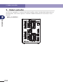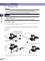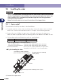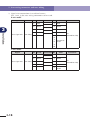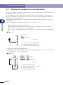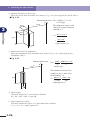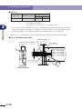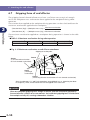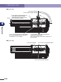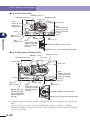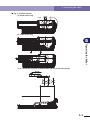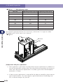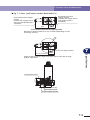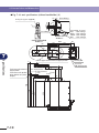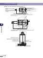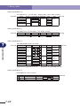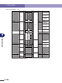
1
YAMAHA ROBOT
Disk Handling Robot
(3, 4-axis specifications)
User’s Manual
ENGLISH
E
E41-Ver. 1.01
Before using the robot (Be sure to read the following notes.)
Before using the robot (Be sure to read the following notes.)
Thanks for your purchase of this YAMAHA disk handling robot.
1. Please be sure to perform the following tasks before using the robot.
Failing to perform the tasks below will require re-teaching of the robot since the origin
position cannot be set to the same previous position. Robot malfunctions (vibration,
noise) may also occur.
The origin positions of this robot are adjusted at the factory before shipment to the
positions indicated in "3.3 Absolute reset" in Chapter 4.
The customer should perform the following absolute reset before any other job.
Absolute reset
This robot only requires the absolute reset to be performed once when the robot is
introduced.
Once the absolute reset is performed, it does not need to be reperformed when the
power is turned on next time.
Perform the absolute reset while referring to "3. Adjusting the origin" in Chapter 4 of
this manual and "Absolute Reset" of the "YAMAHA Robot Controller RCX142 User's
Manual".
! CAUTION
Never enter the robot movement range once the robot servo is turned on as this is
extremely hazardous.
Affixing the origin position sticker
Set in emergency stop when absolute reset is complete, and immediately affix the
origin position stickers according to instructions in "5. Affixing stickers for movement
directions and axis names" in Chapter 4 of this manual.
Even though there is no problem with the robot, the following error messages are
issued when the robot and controller are connected and power first turned on. (Actual
error messages may differ according to how the robot and controller are connected.)
Error messages issued when robot and controller are connected (RCX142)
17.81: D?. ABS. battery wire breakage
17.83: D?. Backup position data error 1
17.85: D?. Backup position data error 2
17.92: D?. Resolver disconnected during power off
17.93: D?. Position backup counter overflow
etc.
1
2. If the X-axis or Y-axis rotation angle is small
Before using the robot (Be sure to read the following notes.)
If the X-axis or Y-axis rotation angle is smaller than 5° so that it always moves in the
same position, an oil film is difficult to be formed on the joint support bearing,
possibly leading to damage to the bearing. In this type of operation, add a movement
so that the joint moves through 90° or more, about 5 times a day.
3. If the Z-axis or R-axis travel distance is short
If the Z-axis or R-axis travel distance is shorter than 5mm so that it always moves in
the same position, an oil film is difficult to be formed on the linear motion bearing,
possibly leading to damage to the bearing. In this type of operation, add a movement
so that the axis moves more than 5mm, about 5 times a day.
2
Introduction
Introduction
The disk handling robot arm is a two-joint manipulator comprising X and Y axes, with a
tool attachment shaft at the manipulator tip. The robot also has a Z-axis that moves the
arm up and down and an R-axis that serves as a travel axis. This configuration is ideal for
handling DVD disks, etc. Please note that this robot is not completely designed for clean
room use because the travel axis does not conform to clean room specifications.
This user's manual describes the safety measures, handling, adjustment, inspection and
maintenance of the disk handling robots for correct, safe and effective use. Be sure to
read this manual carefully before installing the robot. Even after reading this manual,
keep it in a safe and convenient place for future reference. This user's manual should be
used with the robot and considered an integral part of it. When the robot is moved,
transferred or sold, be sure to send this manual to the new user along with the robot, and
explain to the new user the need to read through this manual.
For robot operation and programming details, refer to the "YAMAHA Robot Controller
RCX142 Series User's Manual".
NOTES
• The contents of this manual are subject to change without prior notice.
• Information furnished by YAMAHA in this manual is believed to be reliable.
However, if you find any part unclear or inaccurate in this manual, please contact
YAMAHA sales office or dealer.
YAMAHA MOTOR CO., LTD.
IM Operations
3
MEMO
4
General Contents
Using the Robot Safely
1.
Safety information
1-1
2.
Essential caution items
1-2
3.
Special training for industrial robot operation
1-8
4.
Robot safety functions
1-9
5.
Safety measures for the system
1-10
6.
Trial operation
1-10
7.
Work within the safety enclosure
1-11
8.
Automatic operation
1-12
9.
Adjustment and inspection
1-12
10. Repair and modification
1-12
11. Warranty
1-13
12. CE Marking
1-14
Chapter 2
Functions
1.
Robot manipulator
2-1
2.
Robot controller
2-4
3.
Parameter factory settings
2-5
Custom parameter sheet
Chapter 3
1.
2.
3.
2-5
Installation
Robot installation conditions
1.1
1.2
General Contents
Chapter 1
Installation environments
Installation base
3-1
3-1
3-2
Installation
3-4
2.1
2.2
2.3
2.3.1
2.3.2
2.4
2.4.1
2.4.2
2.5
3-4
3-5
3-6
3-6
3-8
3-10
3-10
3-11
3-12
Unpacking
Checking the product
Moving the robot
4-axis model
3-axis model
Installing the robot
4-axis model
3-axis model
Adjusting the robot base tilt
Protective bonding
3-13
i
General Contents
4.
Robot cable connection
3-15
5.
User wiring connector and user tubing
3-16
5.1
5.2
6.
Attaching the end effector
6.1
6.2
6.3
6.4
6.5
6.6
6.7
7.
8.
User wiring
User tubing
Acceleration
Equation for moment of inertia calculation
Example of moment of inertia calculation
End effector attachment strength and rigidity
Attaching the end effector
Adjusting the end effector tilt (when equipped with hand holder)
Gripping force of end effector
3-21
3-21
3-22
3-25
3-27
3-29
3-33
3-34
Working envelope and mechanical stopper
positions for maximum working envelope
3-35
Base suction tube
3-36
Chapter 4
Adjustment
1.
Overview
4-1
2.
Safety precautions
4-1
3.
Adjusting the origin
4-2
3.1
3.1.1
3.1.2
3.2
3.3
3.3.1
3.3.2
3.4
3.5
3.5.1
3.5.2
3.5.3
4-3
4-3
4-3
4-4
4-5
4-5
4-8
4-9
4-10
4-10
4-12
4-14
Absolute reset method
Sensor method (X-axis and Y-axis)
Stroke end method (Z-axis and R-axis)
Machine reference
Absolute reset procedures
Sensor method (X-axis and Y-axis)
Strike end method (Z-axis and R-axis)
Removing the robot covers
Adjusting the machine reference
Adjusting the X-axis machine reference
Adjusting the Y-axis machine reference
Adjusting the Z-axis machine reference
4.
Setting the soft limits
5.
Affixing stickers for movement directions and axis names 4-17
6.
Adjusting the timing belt tension
6.1
6.2
6.2.1
6.2.2
7.
ii
3-17
3-20
Adjusting the X-axis, Y-axis, and Z-axis motor belt tension
Adjusting the timing belt tension for the X-axis and Y-axis arms
Adjusting the X-axis arm belt
Adjusting the Y-axis arm belt
X-axis and Y-axis arm alignment
4-16
4-19
4-19
4-24
4-24
4-25
4-27
Chapter 5
Operating the Robot
Robot motion
5-1
2.
Operating the robot
5-2
3.
Creating point data, direct teaching, and external forces to arms 5-5
Chapter 6
Periodic Inspection
1.
Overview
6-1
2.
Precautions
6-2
3.
Daily inspection
6-3
4.
Six-month inspection
6-5
5.
Replacing the harmonic drive grease
6-7
5.1
Replacement interval
Chapter 7
General Contents
1.
6-7
Specifications
1.
Basic specifications
7-1
2.
External view and dimensions
7-3
3.
Robot's internal wiring diagram
7-15
4.
Robot's internal tubing
7-16
5.
Wiring tables
7-17
6.
Maintenance parts
7-28
iii
MEMO
iv
Chapter 1
Using the Robot Safely
Contents
1. Safety information
1-1
2. Essential caution items
1-2
3. Special training for industrial robot operation 1-8
4. Robot safety functions
1-9
5. Safety measures for the system
1-10
6. Trial operation
1-10
7. Work within the safety enclosure
1-11
8. Automatic operation
1-12
9. Adjustment and inspection
1-12
10. Repair and modification
1-12
11. Warranty
1-13
12. CE Marking
1-14
1. Safety information
1. Safety information
Warning information in this manual is classified by the following signal words.
DANGER
"DANGER" indicates an imminently hazardous situation which, if not avoided, will result
in death or serious injury.
WARNING
"WARNING" indicates a potentially hazardous situation which, if not avoided, could
result in death or serious injury.
! CAUTION
"CAUTION" indicates a potentially hazardous situation which, if not avoided, could
result in minor or moderate injury or damage to the equipment or software.
Refer to the user's manual by any of the following methods to operate or adjust the robot
safely and correctly.
1. Operate or adjust the robot while referring to the printed version of the user's
manual (available for an additional fee).
2. Operate or adjust the robot while viewing the CD-ROM version of the user's
manual on your computer screen.
3. Operate or adjust the robot while referring to a printout of the necessary pages from
the CD-ROM version of the user's manual.
It is not possible to detail all safety items within the limited space of this manual. So it is
essential that the user have a full knowledge of basic safety rules and also that the
operator makes correct judgments on safety procedures during operation. This manual
and warning labels supplied with or affixed to the robot are written in English. If the
robot operator or service personnel do not understand English, do not permit him/her to
handle the robot.
1-1
1
Using the Robot Safely
Industrial robots are highly programmable, mechanical devices that provide a large
degree of freedom when performing various manipulative tasks. To ensure correct and
safe use of YAMAHA industrial robots, carefully read this manual and make yourself well
acquainted with the contents. FOLLOW THE WARNINGS, CAUTIONS AND
INSTRUCTIONS INCLUDED IN THIS MANUAL. Failure to take necessary safety measures
or mishandling due to not following the instructions in this manual may result in trouble
or damage to the robot and injury to personnel (robot operator or service personnel)
including fatal accidents.
2. Essential caution items
2. Essential caution items
1
Using the Robot Safely
Particularly important cautions for handling or operating the robot are described below.
In addition, safety information about installation, operation, inspection and maintenance
is provided in each chapter. Be sure to comply with these instructions to ensure safe use
of the robot.
(1) Obser ve the following cautions during automatic operation.
Warning labels 1 (Fig. 1-1) are affixed to the robot. See Fig. 2-2 for the locations of
warning labels.
• Install a safety enclosure to keep any person from entering within the movement
range of the robot and suffering injury due to being struck by moving parts.
• Install a safety interlock that triggers emergency stop when the door or panel is
opened.
• Install safeguards so that no one can enter inside except from doors or panels
equipped with safety interlocks.
• The warning labels shown in Fig. 1-1 are supplied with the robot and should be
affixed to a conspicuous spot on doors or panels equipped with safety interlocks.
DANGER
Serious injury or death will result from impact with moving robot.
• Keep outside of guard (safety enclosure) during operation.
• Lock out power or press emergency stop button before approaching robot.
■ Fig. 1-1 Warning label 1
DANGER
Serious injury or death
will result from impact
with moving robot.
• Keep outside of guard
during operation.
• Lock out power before
approaching robot.
(2) Use caution to prevent hands or fingers from being pinched or crushed.
Warning labels 2 (Fig. 1-2) are affixed to the robot. See Fig. 2-2 for the locations of
warning labels.
Be careful not to let hands or fingers be pinched or crushed by the moving parts of the
robot during transportation or teaching.
WARNING
Moving parts can pinch or crush hands. Keep hands away from robot arms.
1-2
2. Essential caution items
■ Fig. 1-2 Warning label 2
WARNING
1
(3) Follow the instructions on warning labels and in this manual.
Warning label 3 (Fig. 1-3) is affixed to the robot. See Fig. 2-2 for the locations of
warning labels.
• Be sure to read the warning labels and this manual carefully and make sure you
thoroughly understand their contents before attempting installation and operation
of the robot.
• Before starting robot operation, even after you have read through this manual, read
again the procedures and cautions relating to your work as well as the description
in this chapter (Chapter 1, "Using the Robot Safely").
• Never install, adjust, inspect or service the robot in any manner that does not
comply with the instructions in this manual.
WARNING
Improper installation or operation can result in serious injury or death. Read user's
manual and all warning labels before installation and operation.
■ Fig. 1-3 Warning label 3
WARNING
Improper Installation or operation
can result in serious injury or
death.
Read user's (owner's)
manual and all warning labels
before operation.
(4) Do not use the robot in environments containing inflammable gas, etc.
WARNING
• This robot was not designed for operation in environments where inflammable or
explosive substances are present.
• Do not use the robot in environments containing inflammable gas, dust or liquids.
Explosions or fire may otherwise result.
1-3
Using the Robot Safely
Moving parts can
pinch or crush.
Keep hands away
from robot arms.
2. Essential caution items
(5) Do not use the robot in locations possibly subject to electromagnetic interference, etc.
1
WARNING
Using the Robot Safely
Avoid using the robot in locations subject to electromagnetic interference,
electrostatic discharge or radio frequency interference. Malfunction may otherwise
occur.
(6) Use caution when releasing the Z-axis (vertical axis) brake.
WARNING
The Z-axis will slide down when the Z-axis brake is released, causing a hazardous
situation.
• Press the emergency stop button and prop up the Z-axis with a support stand before
releasing the brake.
• Use caution not to let your body get caught between the Z-axis and installation
base when releasing the brake to perform direct teach.
(7) Provide safety measures for end effector (gripper, etc.).
WARNING
• End effectors must be designed and manufactured so that they cause no hazards
(for example, loosening of workpiece) even if power (electricity, air pressure, etc.) is
shut off or power fluctuations occur.
• If there is a possible danger that the object gripped by the end effector may fly off
or drop, then provide appropriate safety protection taking into account the object
size, weight, temperature and chemical properties.
(8) Be cautious of possible Z-axis movement when the controller is turned off or emergency
stop is triggered. (2-axis robots with air-driven Z-axis)
WARNING
The Z-axis moves up when the power to the controller or PLC is turned off, the program
is reset, emergency stop is triggered, or air is supplied to the solenoid valve for the
Z-axis air cylinder.
• Do not let hands or fingers get caught and squeezed by moving parts of the Z-axis.
• Keep the usual robot position in mind so that the Z-axis will not interfere with obstacles
during raising of the Z-axis, except in case of emergency stop.
1-4
2. Essential caution items
(9) Use caution when the Z-axis is interfering with peripheral equipment.
(2-axis robots with air driven Z-axis)
WARNING
(10) Use caution on Z-axis movement when air supply is stopped.
(2-axis robots with air-driven Z-axis)
WARNING
The Z-axis may suddenly drop when the air pressure to the Z-axis air cylinder solenoid
valve is reduced, creating a hazardous situation.
Turn off the controller and place a prop or support under the Z-axis before cutting off
the air supply.
(11) Use caution when disassembling or replacing the pneumatic equipment.
WARNING
Air or parts may fly outwards if pneumatic equipment is disassembled or parts
replaced while air is still supplied.
• Do service work after first turning off the controller and reducing the air pressure.
• Before reducing the air pressure, place a support stand under the Z-axis (2-axis robots
with air-driven Z-axis) because it will drop under its own weight.
(12) Use caution when removing the Z-axis motor.
WARNING
The Z-axis will drop when the Z-axis motor is removed, causing a hazardous situation.
• Turn off the controller and set a support stand under the Z-axis before removing the motor.
• Use caution not to allow hands or body to be squeezed or crushed by moving parts
on the Z-axis or between the Z-axis and the installation base.
1-5
Using the Robot Safely
When the Z-axis comes to a stop due to obstructions from peripheral equipment, the
Z-axis may move suddenly when the obstruction is removed, causing injury such as
pinched or crushed hands.
• Turn off the controller and reduce the air pressure before attempting to remove the
obstruction.
• Before reducing the air pressure, place a support stand under the Z-axis because it
will drop under its own weight.
1
2. Essential caution items
(13) Use caution during inspection of controller.
1
WARNING
Using the Robot Safely
• When you need to touch the terminals or connectors on the outside of the controller
during inspection, always first turn off the controller power switch and also the power
source in order to prevent possible electrical shock.
• Never touch any internal parts of the controller.
For precautions on handling the controller, refer to the "YAMAHA Robot Controller
User's Manual".
(14) Consult us for corrective action when the robot is damaged or malfunction occurs.
WARNING
If any part of the robot is damaged or any malfunction occurs, continuous operation
may be very dangerous. Please consult YAMAHA sales office or dealer for corrective
action.
Damage or Trouble
Possible Danger
Damage to machine harness or robot cable
Electrical shock, malfunction of robot
Damage to exterior of robot
Flying outwards of damaged parts during
robot operation
Abnormal operation of robot
(positioning error, excessive vibration, etc.)
Malfunction of robot
Z-axis brake trouble
Dropping of load
(15) Use caution not to touch the high temperature motor or speed reduction gear casing.
WARNING
The motor and speed reduction gear casing are extremely hot after automatic
operation, so burns may occur if these are touched.
Before touching these parts during inspections or servicing, turn off the controller, wait
for a while and check that the temperature has cooled.
(16) Do not remove, alter or stain the warning labels.
WARNING
If warning labels are removed or difficult to see, necessary cautions may not be
taken, resulting in an accident.
• Do not remove, alter or stain the warning labels on the robot.
• Do not allow the warning labels to be hidden by the device installed to the robot by
the user.
• Provide proper lighting so that the symbols and instructions on the warning labels
can be clearly seen even from the outside of safety enclosure.
1-6
2. Essential caution items
(17) Protective bonding
WARNING
1
Be sure to ground the robot and controller to prevent electrical shock.
! CAUTION
The robot must be operated with an acceleration rate that is appropriate for the
manipulator tip's weight and moment of inertia. If this is not observed, premature end
to the life of the drive units, damage to the robot parts or residual vibration during
positioning may result.
(19) Do not use the robot for tasks requiring motor thrust.
! CAUTION
Avoid using the disk handling robot for tasks which make use of motor thrust (pressfitting, burr removal, etc.). These tasks may cause malfunctions of the robot.
(20) If the X-axis or Y-axis rotation angle is small
! CAUTION
If the X-axis or Y-axis rotation angle is smaller than 5° so that it always moves in the
same position, an oil film is difficult to be formed on the joint support bearing, possibly
leading to damage to the bearing. In this type of operation, add a movement so that
the joint moves through 90° or more, about 5 times a day.
(21) If the Z-axis or R-axis travel distance is short
! CAUTION
If the Z-axis or R-axis travel distance is shorter than 5mm so that it always moves in the
same position, an oil film is difficult to be formed on the linear motion bearing,
possibly leading to damage to the bearing. In this type of operation, add a movement
so that the axis moves more than 5mm, about 5 times a day.
1-7
Using the Robot Safely
(18) Be sure to make correct parameter settings.
3. Special training for industrial robot operation
3. Special training for industrial robot operation
1
Using the Robot Safely
Companies or factories using industrial robots must make sure that every person, who
handles the robot such as for teaching, programming, movement check, inspection,
adjustment and repair, has received appropriate training and also has the skills needed to
perform the job correctly and safely. Since the YAMAHA disk handling robots fall under
the industrial robot category, the user must observe local regulations and safety standards
for industrial robots, and provide special training for every person involved in robotrelated tasks (teaching, programming, movement check, inspection, adjustment, repair,
etc.).
1-8
4. Robot safety functions
4. Robot safety functions
(1) Overload detection
1. Insert a timer in the program.
2. Reduce the acceleration coefficient.
(2) Overheat detection
This function detects an abnormal temperature rise in the driver inside the controller
and shuts off the servo power. If an overheat error occurs, take the following
measures.
1. Insert a timer in the program.
2. Reduce the acceleration coefficient.
(3) Soft limits
Soft limits can be set on each axis to limit the working envelope in manual operation
after return-to-origin and during automatic operation. The working envelope is the
area limited by soft limits.
(4) Mechanical stoppers
If the servo power is suddenly shut off during high-speed operation by emergency stop
or safety functions, these mechanical stoppers prevent the axis from exceeding the
movement range. The movement range is the area limited by mechanical stoppers.
• The X, Y, Z and R axes have fixed mechanical stoppers at their movement range
limits in plus and minus directions.
WARNING
Axis movement will not stop immediately after the servo power supply is shut off by
emergency stop or other safety functions, so use caution.
(5) Z-axis (vertical axis) brake
An electromagnetic brake is installed on the Z-axis to prevent the Z-axis from sliding
down when servo power is turned off. This brake is working when the controller
power is off or the Z-axis servo power is off even when the controller power is on. The
Z-axis brake can be released by means of the programming unit or by a command in
the program when the controller power is on.
WARNING
The Z-axis will slide down when the Z-axis brake is released, creating a hazardous situation.
• Press the emergency stop button and prop the Z-axis with a support stand before
releasing the brake.
• Use caution not to let your body get caught between the Z-axis and installation
base when releasing the brake to perform direct teach.
1-9
1
Using the Robot Safely
This function detects an overload applied to the motor and shuts off the servo power.
If an overload error occurs, take the following measures.
5. Safety measures for the system
5. Safety measures for the system
1
Using the Robot Safely
Since the robot is commonly used in conjunction with an automated system, dangerous
situations are more likely to occur from the automated system than from the robot itself.
Accordingly, appropriate safety measures must be taken on the part of the system
manufacturer according to the individual system. The system manufacturer should
provide a proper instruction manual for safe, correct operation and servicing of the
system.
6. Trial operation
After making installations, adjustments, inspections, maintenance or repairs to the robot,
make a trial run using the following procedures.
(1) If a safety enclosure has not yet been provided right after installation of the robot,
rope off or chain off around the movement area of the manipulator in place of the
safety enclosure, and obser ve the following points.
1. Use sturdy, stable posts which will not fall over easily.
2. The rope or chain should be easily visible by everyone around the robot.
3. Place a sign to keep the operator or other personnel from entering the movement
range of the manipulator.
(2) Check the following points before turning on the controller.
1. Is the robot securely and correctly installed?
2. Are the electrical connections to the robot correct?
3. Are items such as air pressure correctly supplied?
4. Is the robot correctly connected to peripheral equipment?
5. Have safety measures (safety enclosure, etc.) been taken?
6. Does the installation environment meet the specified standards?
(3) After the controller is turned on, check the following points from outside the safety enclosure.
1. Does the robot start and stop as intended? Can the operation mode be selected
correctly?
2. Does each axis move as intended within the soft limits?
3. Does the end effector move as intended?
4. Are the signal transmissions to the end effector and peripheral equipment correct?
5. Does emergency stop work?
6. Are the teaching and playback functions normal?
7. Are the safety enclosure and interlock working as intended?
8. Does the robot move correctly during automatic operation?
1-10
7. Work within the safety enclosure
7. Work within the safety enclosure
1) Origin position setting (See section 3 in Chapter 4.)
2) Soft limit setting (See section 4 in Chapter 4.)
3) X-axis and Y-axis arm alignment (See section 7 in Chapter 4.)
4) Teaching
For items 1), 2) and 3), follow the precautions and procedure described in each
section. To perform item 4), refer to the description in (2) below.
(2) Teaching
When performing teaching within the safety enclosure, comply with the instructions
listed below.
1) Check or perform the following points from outside the safety enclosure.
1. Make sure that no hazards are present within the safety enclosure by a visual
check.
2. Check that the programming unit MPB operates correctly.
3. Check that no failures are found in the robot.
4. Check that emergency stop works correctly.
5. Select teaching mode and prohibit automatic operation.
2) Never enter the movement range of the robot while within the safety enclosure.
1-11
1
Using the Robot Safely
(1) When work is required inside the safety enclosure, always turn off the controller and
place a sign indicating that the robot is being adjusted or ser viced in order to keep
any other person from touching the controller switch or operation panel, except for the
following cases.
8. Automatic operation
8. Automatic operation
1
Automatic operation described here includes all operations in AUTO mode.
Using the Robot Safely
(1) Check the following before starting automatic operation.
1. No one is within the safety enclosure.
2. The programming unit and tools are in their specified locations.
3. The alarm or error lamps on the robot and peripheral equipment do not flash.
4. The safety enclosure is securely installed with safety interlocks actuated.
(2) Obser ve the following during automatic operation or in cases where an error occurs.
1) After automatic operation has started, check the operation status and warning lamp
to ensure that the robot is in automatic operation.
2) Never enter the safety enclosure during automatic operation.
3) If an error occurs in the robot or peripheral equipment, observe the following
procedure before entering the safety enclosure.
1. Press the emergency stop button to set the robot to emergency stop.
2. Place a sign on the start switch, indicating that the robot is being inspected in
order to keep any other person from touching the start switch and restarting the
robot.
9. Adjustment and inspection
Do not attempt any installation, adjustment, inspection or maintenance unless it is
described in this manual.
10. Repair and modification
Do not attempt any repair, parts replacement and modification unless described in this
manual. These works require technical knowledge and skill, and may also involve work
hazards.
1-12
11. Warranty
11. Warranty
The YAMAHA robot and/or related product you have purchased are warranted against
the defects or malfunctions as described below.
Using the Robot Safely
Warranty description:
1
If a failure or breakdown occurs due to defects in materials or workmanship in the
genuine parts constituting this YAMAHA robot and/or related product within the
warranty period, then YAMAHA will repair or replace those parts free of charge
(hereafter called "warranty repair").
Warranty Period:
The warranty period ends when any of the following applies:
1) After 18 months (one and a half year) have elapsed from the date of shipment
2) After one year has elapsed from the date of installation
3) After 2,400 hours of operation
Exceptions to the Warranty:
This warranty will not apply in the following cases:
1) Fatigue arising due to the passage of time, natural wear and tear occurring during
operation (natural fading of painted or plated surfaces, deterioration of parts
subject to wear, etc.)
2) Minor natural phenomena that do not affect the capabilities of the robot and/or
related product (noise from computers, motors, etc.).
3) Programs, point data and other internal data that were changed or created by the
user.
Failures resulting from the following causes are not covered by warranty repair.
1) Damage due to earthquakes, storms, floods, thunderbolt, fire or any other natural
or man-made disasters.
2) Troubles caused by procedures prohibited in this manual.
3) Modifications to the robot and/or related product not approved by YAMAHA or
YAMAHA sales representatives.
4) Use of any other than genuine parts and specified grease and lubricants.
5) Incorrect or inadequate maintenance and inspection.
6) Repairs by other than authorized dealers.
YAMAHA MOTOR CO., LTD. MAKES NO OTHER EXPRESS OR IMPLIED WARRANTIES,
INCLUDING ANY IMPLIED WARRANTY OF MERCHANTABILITY OR FITNESS FOR ANY
PARTICULAR PURPOSE. THE WARRANTY SET FORTH ABOVE IS EXCLUSIVE AND IS IN
LIEU OF ALL EXPRESSED OR IMPLIED WARRANTIES, INCLUDING WARRANTIES OF
MERCHANTABILITY, FITNESS FOR A PARTICULAR PURPOSE, OR WARRANTIES
ARISING FROM A COURSE OF DEALING OR USAGE OF TRADE.
YAMAHA MOTOR CO., LTD. SOLE LIABILITY SHALL BE FOR THE DELIVERY OF THE
EQUIPMENT AND YAMAHA MOTOR CO., LTD. SHALL NOT BE LIABLE FOR ANY
CONSEQUENTIAL DAMAGES (WHETHER ARISING FROM CONTRACT, WARRANTY,
NEGLIGENCE OR STRICT LIABILITY). YAMAHA MOTOR CO., LTD. MAKES NO
WARRANTY WHATSOEVER WITH REGARD TO ACCESSORIES OR PARTS NOT
SUPPLIED BY YAMAHA MOTOR CO., LTD.
1-13
12. CE Marking
12. CE Marking
1
When the YAMAHA robots are exported to or used in EU (European Union) countries,
refer to the separate "YAMAHA Robot Controller User's Manual" or "CE Marking
Supporting Supplement Manual" for related information about CE marking.
Using the Robot Safely
1-14
Chapter 2
Functions
Contents
1. Robot manipulator
2-1
2. Robot controller
2-4
3. Parameter factory settings
2-5
Custom parameter sheet
2-5
1. Robot manipulator
1. Robot manipulator
The disk handling robot can move as illustrated in Fig. 2-1 below. The (+) and (-) signs
show the direction in which the robot moves when the jog keys on the programming unit
are pressed (standard setting at the factory).
■ Fig. 2-1 Robot motions
Functions
Tool (end effector)
attachment shaft
(+)
(−) Y-axis
origin position
(−)
Y-axis
X, Y, Z and R axis
origin positions
X-axis
(+)
Tool attachment
shaft direction is
held during Y-axis
forward motion.
R-axis
(travel axis)
X-axis rotational motion
Y-axis forward motion
(Direct forward motion of
tool attachment shaft)
(+)
(−)
Z-axis
origin position
R-axis
origin position
(−)
(+)
Z-axis up/down motion
2
R-axis linear motion
2-1
1. Robot manipulator
Fig. 2-2 to Fig. 2-5 below show part names and functions of each robot model.
■ Fig. 2-2 4-axis model (without hand holder)
Tool (end effector)
attachment shaft
X-axis arm
2
Y-axis arm
Functions
Warning label 1
Warning label 2
Warning label 3
Y-axis motor and speed reduction gear
X-axis motor and speed reduction gear
Z-axis ball screw,
guide and motor
Robot cable
Base tilt adjustment screw
Travel axis (R-axis)
Warning label 2
Cable carrier
User tubing 2
User tubing 1
User wiring
Serial number label
Wiring box
User wiring connector
(pins 1 to 4 usable)
User tubing 2 (F4)
ground terminal
User tubing 1 (F4)
Suction coupler (F12 × 2)
2-2
1. Robot manipulator
■ Fig. 2-3 4-axis model (with hand holder)
User tubing 1 at lower part
End effector attachment
Hand holder
(User tubing 2 and user wiring inside)
2
Functions
■ Fig. 2-4 3-axis model (without hand holder)
Suction coupler (F12s2)
User wiring connector (pins 1 to 4 usable)
Robot cable
User tubing 1 (F4)
User tubing 2 (F4)
Ground terminal
Base tilt adjustment screw
■ Fig. 2-5 3-axis model (with hand holder)
Hand holder
2-3
2. Robot controller
2. Robot controller
2
An RCX142 controller is used with the disk handling robot. For detailed information on
the controller, refer to the separate "YAMAHA Robot Controller RCX142 Series User's
Manual".
■ Fig. 2-6 RCX142
MOTOR
OP.1
Functions
PWR
OP.3
MPB
XM
RCX142
MODEL.
SER. NO.
MANUFACTURED
FACTORY AUTOMATION EQUIPMENT MADE IN JAPAN
SRV
ERR
ROB
I/O
CAUTION
READ INSTRUCTION
MANUAL
XY
YM
BATT
COM
ROB
I/O
XY
ZR
ZR
OP.2
OP.4
RGEN
ZM
STD.DIO
P
SAFETY
N
ACIN
RM
L
N
200-230V~
50-60Hz
MAX.2500VA
2-4
3. Parameter factory settings
3. Parameter factor y settings
This robot is a custom-order item, and therefore has customized parameters. Be sure to
make a backup copy of the parameter factory settings. The parameter settings will be lost
if the parameters are initialized. In that event, use the backup data to download the
parameter settings again. The parameters are indicated on the custom parameter sheet
attached to each robot.
To purchasers of this custom-made robot
Thank you for purchase of this YAMAHA robot.
This robot is a custom-order item, and therefore shipped with parameters customized by
changing the standard robot settings. If this robot is used with parameter settings that
differ from the "customized parameter settings", this may cause problems such as
malfunctions. Do not change the customized parameter settings indicated on the custom
parameter sheet.
The parameter settings will be lost if the robot parameters are initialized. In that event,
set the parameters again.
Make a backup of the parameter settings before using the robot.
Please keep the custom parameter sheet carefully along with the user's manual, as it will
be needed in cases where the parameters have to be set again.
Setting models
Model
Mechanical unit
Disk handling 3-axis robot + F17
Controller
RCX142
Serial No.
Date of manufacture
(month/year)
Customized parameter settings
Customized parameter settings are shown below. Boxes left blank indicate standard
parameter settings.
Robot configuration
Configuration
Main robot
Robot name
MULTI
Robot No.
170
Axis configuration
Configuration
M1
M2
M3
M4
Axis name
F14H-20
F14-20
F17-20V
F17-10
Axis No.
4060
4050
4072
4071
Custom setting
Robot settings
Name
Name
Tip mass
Return-to-origin sequence
Changed value
Changed value
0
231456
* On the 3-axis model (X, Y and Z axes) using an RCX142 controller, only M1 to
M3 settings are needed.
2-5
Functions
Custom parameter sheet
2
3. Parameter factory settings
Axis settings (Blank boxes indicate default settings. Do not change them.)
Changed value
M1
M2
M3
+ soft limit
386844
269654
163840
2
- soft limit
-386844
-4552
Return-to-origin method
Sensor
Sensor
Functions
Name
M4
Axis polarity
+
+
+
Acceleration
1300
1200
3000
Kvp
6000
3900
1500
Kvi
4000
2600
1000
285
246
257
Motor model
Overload reference
2949
Overload time
2548
Id max
380
Id limit
22
Maximum torque
command
Maximum motor
revolution
1255
5000
5000
Kip
48
Kii
32
Origin position
return pulse
Stroke-end origin
position torque
←Never increase
acceleration
more than this
level.
2000
←Never change
maximum
motor
revolution.
0
80
* On the 3-axis model (X, Y and Z axes) using an RCX142 controller, only M1 to
M3 settings are needed.
2-6
Chapter 3
Installation
Contents
1. Robot installation conditions
1.1
1.2
Installation environments
Installation base
2. Installation
2.1
2.2
2.3
2.3.1
2.3.2
2.4
2.4.1
2.4.2
2.5
Unpacking
Checking the product
Moving the robot
4-axis model
3-axis model
Installing the robot
4-axis model
3-axis model
Adjusting the robot base tilt
3-1
3-1
3-2
3-4
3-4
3-5
3-6
3-6
3-8
3-10
3-10
3-11
3-12
3. Protective bonding
3-13
4. Robot cable connection
3-15
5. User wiring connector and user tubing
3-16
5.1
5.2
User wiring
User tubing
6. Attaching the end effector
6.1
6.2
6.3
6.4
6.5
6.6
6.7
Acceleration
Equation for moment of inertia calculation
Example of moment of inertia calculation
End effector attachment strength and rigidity
Attaching the end effector
Adjusting the end effector tilt (when equipped with hand holder)
Gripping force of end effector
3-17
3-20
3-21
3-21
3-22
3-25
3-27
3-29
3-33
3-34
7. Working envelope and mechanical stopper
positions for maximum working envelope
3-35
8. Base suction tube
3-36
1. Robot installation conditions
1. Robot installation conditions
1.1
Installation environments
Be sure to install the robot in the following environments.
Items
Specifications
0 to 40°C
Allowable ambient
humidity
35 to 85% RH (non condensation)
Altitude
0 to 1000 meters above sea level
3
Avoid installing near water, cutting water, oil, dust, metallic chips and
organic solvent.
Ambient
environments
Avoid installation near corrosive gas and corrosive materials.
Avoid installation in atmosphere containing inflammable gas, dust or liquid.
Avoid installation near objects causing electromagnetic interference,
electrostatic discharge or radio frequency interference.
Vibration
Do not subject to impacts or vibrations.
Air supply
pressure, etc.
Below 0.58MPa (6.0kgf/cm 2); clean dry air not containing deteriorated
compressor oil; filtration 40µm or less
Working space
Allow sufficient space margin to perform jobs (teaching, inspection, repair, etc.)
For detailed information on how to install the robot controller, refer to the separate
"YAMAHA Robot Controller User's Manual".
WARNING
• Avoid installing the robot in locations where the ambient conditions may exceed the
allowable temperature or humidity, or in environments where water, corrosive gases,
metallic powder or dust are generated. Malfunction, failure or short circuits may
otherwise result.
• This robot was not designed for operation in environments where inflammable or
explosive substances are present. Do not use the robot in environments containing
inflammable gas, dust or liquids. Explosions or fire could otherwise result.
• Avoid using the robot in locations subject to electromagnetic interference, electrostatic
discharge or radio frequency interference. Malfunction may otherwise occur.
• Do not use the robot in locations subject to excessive vibration. Robot installation
bolts may otherwise become loose causing the robot to fall over.
3-1
Installation
Allowable ambient
temperature
1. Robot installation conditions
1.2
Installation base
WARNING
Always install the robot on a level surface, with the robot base mount facing
downward. Grease may leak out from the speed reduction gear if the robot is installed
in such a way that the base mount does not face downward.
3
! CAUTION
Installation
• The manipulator positioning may decrease if the installation surface precision is
insufficient.
• If the installation base is not sufficiently rigid and stable or a thin metallic plate is
attached to the installation base, vibration (resonance) may occur during operation,
causing detrimental effects on the manipulator work.
1) Prepare a sufficiently rigid and stable installation base, taking account of the robot
weight including the end effector (gripper), workpiece and reaction force while the
robot is operating.
The maximum reaction force (see Fig.3-1) applied to the robot is as shown below.
These values are an instantaneous force applied to the robot during operation and do
not indicate the maximum load capacity.
Maximum reaction force during robot operation
Fxmax
3-2
F Y max
Mxmax
Fzmax
N
kgf
N
Kgf
Nm
kgfm
N
Kgf
1019
104
686
70
56
6
294
30
1. Robot installation conditions
■ Fig. 3-1 Maximum reaction force applied during operation
FZmax
FYmax
MXmax
3
Installation
FXmax
4-axis model
FZmax
FYmax
FYmax
MXmax
3-axis model
2) The installation base surface must be machined within a flatness of ±0.05mm/500mm.
The robot base mount must be installed facing down and in a level position.
3) Tap holes into the surface of the installation base. Refer to "2. External view and
dimensions" in Chapter 7 for machining dimensions and positions.
4) Securely fix the installation base on the floor with anchor bolts.
3-3
2. Installation
2. Installation
2.1
Unpacking
WARNING
3
The robot and controller are heavy. Take sufficient care not to drop them during
moving or unpacking as this may damage the equipment or cause bodily injury.
Installation
! CAUTION
Allow only properly qualified personnel to operate equipment such as forklifts that
require a license to use. Equipment and tools used for moving the robot should be
serviced daily.
The disk handling robot comes packed with a robot controller and accessories, according
to the order specifications. Using a carrying cart (dolly) or forklift, move the package to
near the installation base. Take sufficient care not to apply shocks to the equipment
when unpacking it.
■ Fig. 3-2 Packed state
Robot manipulator
Travel axis
Robot controller
and accessories
4-axis model (3-axis model does not have travel axis.)
3-4
2. Installation
2.2
Checking the product
After unpacking, check the product configuration and conditions.
! CAUTION
If there is any damage due to transportation or insufficient parts, please notify your
YAMAHA sales office or dealer immediately.
3
A
X
Z
Installation
■ Fig. 3-3 Product configuration
4-axis model robot
(3-axis model does not
have travel axis.)
B
Y
R
Movement direction and
axis name label
CD-ROM User’s Manual
or
User’s Manual
42
OP.3
OP.1
Robot cable
RCX1
MODEL.
NO.
IN JAPAN
MADE
TURED
MANUFAC
N EQUIPMENT
AUTOMATIO
FACTORY
SER.
ION
CAUT
MPB
MOTOR
PWR
CTION
INSTRU
READ L
MANUA
SRV
ERR
XM
ROB
I/O
User wiring connector
T
BAT
XY
XY
YM
COM
ZR
N
RGE
ROB
I/O
OP.4
OP.2
ZR
P
N
.DIO
STD
ACIN
ZM
ETY
SAF
L
N
RM
Pin
-230V~
200 60Hz
50- 500VA
X.2
MA
RCX142 controller
For 4-axis model
For 3-axis model
O-ring (for sealing of end effector attachment )
Model without hand holder : S7 2 pcs
Model with hand holder
: S5 1 pc
Warning label
Options
OP. DIO connector
MPB programming unit
Expansion I/O connector
3-5
2. Installation
2.3
Moving the robot
WARNING
Serious injury may occur if the robot falls and pins someone underneath it.
• Do not allow any part of your body within the area beneath the robot during work.
• Always wear a helmet, safety shoes and gloves during work.
3
! CAUTION
Installation
• Allow only properly qualified personnel to operate equipment such as cranes that
require a license to use.
• Equipment and tools used for moving the robot should be serviced daily.
2.3.1 4-axis model
The robot weighs more than 70kg so take suitable precautions when carrying the robot.
Use 3 or more people for the following work.
1) Move each axis to its origin position, and then turn off the controller and disconnect
the robot cable from the controller. (The robot is bolted to a pallet at the time of
shipment.)
■ Fig. 3-4
Installation base or pallet
(This figure shows a pallet.)
Push here by hand to
move robot.
Push here by hand to
move robot.
(a)
Lifter's fork
(b)
New installation base
(d)
(c)
2) Wind the robot cable around the robot base and fasten the robot cable with adhesive
tape. (See Fig. 3-4 (a).)
3-6
2. Installation
3) In the following work, hold the robot being careful to keep it balanced so it will not
fall over.
Remove the R-axis (travel axis) mounting bolts. (See "2.4 Installing the robot".)
4) Move the robot to one edge of the installation base (or pallet), by pushing the robot
toward the edge with two people, one each at the ends of the R-axis (travel axis).
6) Shift the robot onto the forks of the lifter with two people. (See Fig. 3-4 (b).) Hold the
robot while the lifter is moving up or down to ensure the robot will not fall over.
7) Move the robot on the lifter to the new installation base and then position the lifter
against the edge of the installation base. At this point, hold the robot to ensure it will
not fall over. (See Fig. 3-4 (c).)
8) Shift the robot onto the installation base with two people. Make sure the robot is
stably placed on the installation base. (See Fig. 3-4 (d).)
9) Bolt the robot promptly by referring to the description in "2.4 Installing the robot".
3-7
3
Installation
5) Have another person use a lifter to position it against the edge of the installation base
(or pallet). Use a lifter with a maximum payload capacity sufficient to support the
robot mass.
2. Installation
2.3.2 3-axis model
The robot weighs more than 40kg so take suitable precautions when carrying the robot.
Use 3 or more people for the following work.
1) Move each axis to its origin position, and then turn off the controller and disconnect
the robot cable from the controller. (The robot is bolted to a pallet at the time of
shipment.)
3
■ Fig. 3-5
Installation
Installation base or pallet
(This figure shows a pallet.)
Push here
(same on
opposite side)
by hand to
move robot.
Push here (same on
opposite side) by
hand to move robot. (a)
Lifter's fork
(b)
New installation base
(d)
(c)
2) Wind the robot cable around the robot base and fasten the robot cable with adhesive
tape. (See Fig. 3-5 (a).)
3) In the following work, hold the robot being careful to keep it balanced so it will not
fall over.
Remove the robot base mounting bolts. (See "2.4 Installing the robot".)
4) Move the robot to one edge of the installation base (or pallet), by pushing the robot
toward the edge with two people, one at each end of the robot base.
5) Have another person use a lifter to position it against the edge of the installation base
(or pallet). Use a lifter with a maximum payload capacity sufficient to support the
robot weight.
6) Shift the robot onto the forks of the lifter with two people. (See Fig. 3-5 (b).) Hold the
robot while the lifter is moving up or down to ensure the robot will not fall over.
3-8
2. Installation
7) Move the robot on the lifter to the new installation base and then position the lifter
against the edge of the installation base. At this point, hold the robot to ensure it will
not fall over. (See Fig. 3-5 (c).)
8) Shift the robot onto the installation base with two people. Make sure the robot is
stably placed on the installation base. (See Fig. 3-5 (d).)
3
9) Bolt the robot promptly by referring to the description in "2.4 Installing the robot".
Installation
3-9
2. Installation
2.4
Installing the robot
WARNING
3
• When installing the robot, use the specified size and number of bolts that match the
depth of tapped holes in the installation base, and securely tighten the bolts to the
correct torque. If this is not observed, the robot might fall over during operation
causing a serious accident.
• Make sure that the bolts do not reach the bottom of the tapped holes.
Installation
2.4.1 4-axis model
The method for installing the robot is described below.
1) Tap holes into the surface of the installation base where the robot is to be installed.
Refer to "2. External view and dimensions" in Chapter 7 for machining positions.
2) Remove the screws holding the upper cover of the robot and remove the upper cover.
Move the slider to a position where the mounting holes in the bottom of the robot are seen.
3) Fix the robot to the installation base with the specified bolts.
Bolt size
Tightening torque
Number of bolts
M8
37Nm (380Kgfcm)
10
Depth of tapped holes in installation base:
Iron installation base
15mm or more (bolt length 40mm or more)
Aluminum installation base 25mm or more (bolt length 50mm or more)
Recommended bolt
: JIS B 1176 hex socket head bolt, or equivalent
Strength class JIS B 1051 12.9, or equivalent
■ Fig. 3-6 Installing the robot
10 M8 bolts for robot installation
(Screw into holes just outside guide.)
Remove upper cover mounting
screws (2 pcs).
Guide
Slider
Remove upper cover mounting screws (4 pcs).
Upper cover
4) Reattach the upper cover.
3-10
2. Installation
2.4.2 3-axis model
Fix the robot securely with 4 hex socket head bolts as shown in Fig. 3-7.
Tightening torque
Bolt size
Tightening torque
Number of bolts
M8
37Nm (380Kgfcm)
4
■ Fig. 3-7 Installing the robot
Installation base
Hex socket head bolt
3-11
3
Installation
Depth of tapped holes in installation base:
Iron installation base
17mm or more (bolt length 30mm or more)
Aluminum installation base 27mm or more (bolt length 40mm or more)
Recommended bolt
: JIS B 1176 hex socket head bolt, or equivalent
Strength class JIS B 1051 12.9 or higher, or equivalent
2. Installation
2.5
Adjusting the robot base tilt
Use the following method to adjust the robot base tilt versus the slider (4-axis model) or
installation base (3-axis model). (See Fig. 3-8.) Making this adjustment also affects the
robot base alignment that was made at the factory prior to shipment, so do not attempt
this adjustment unless necessary.
■ Fig. 3-8 4-axis model
3
Installation
Base
4 base tilt adjustment screws
(width across flats: 6mm)
4 screw lock nuts (width across flats: 13mm)
4 M8 bolts for base installation
Slider
■Fig. 3-8 3-axis model
Base
Installation base
4 base tilt adjustment screws
(width across flats: 6mm)
4 screw lock nuts (width across flats: 13mm)
4 M8 bolts for base installation
1) Loosen the M8 bolts securing the robot base.
2) Loosen the nuts securing the robot base tilt adjustment screws.
3) Tighten the robot base tilt adjustment screws to adjust the tilt as needed.
4) When finished, retighten the M8 bolts to a torque of 37Nm (380Kgfcm) to secure the
robot base.
5) Retighten the nuts to secure the robot base tilt adjustment screws.
3-12
3. Protective bonding
3. Protective bonding
WARNING
• Be sure to ground the robot and controller to prevent electrical shock.
• Turn off the controller before grounding the robot.
3
The robot must be grounded as follows:
(Symbol 417-IEC-5019)
■ Fig. 3-9 4-axis model
Ground terminal
Ground symbol
3-13
Installation
1) Provide a terminal marked "PE" for the protective conductor of the entire system and
connect it to an external protective conductor. In addition, securely connect the
ground terminal on the robot to the same protective conductor. (See Fig. 3-9.)
3. Protective bonding
■ Fig. 3-9 3-axis model
3
Installation
Ground symbol
M4 ground terminal
2) An M4 machine screw with a spring washer and a tooth lock washer is attached to
the ground terminal. Tighten the M4 machine screw by inserting it through the tooth
lock washer, ring terminal and spring washer. (See Fig. 3-10.)
■ Fig. 3-10
Machine screw with spring washer
Ring terminal
Tooth lock washer
3) When the tool (end effector) uses an electrical device which, if it malfunctions, might
make contact with the power supply, ground the end effector properly on your
responsibility since no ground terminal is provided for such a device on the robot
body.
4) For protective bonding on the robot body to comply with CE marking, follow the
instructions on controller protective bonding explained in the "YAMAMA Robot
Controller User's Manual or "CE Marking Supporting Supplement Manual".
5) Use a ground cable with a conductor wire cross section of at least 2.0mm 2 and a
length within 1 meter.
On the 4-axis model, take out the ground cable through the cutout in the wiring box
so that it will not interfere with the movable parts.
3-14
4. Robot cable connection
4. Robot cable connection
For details on connecting the robot cable to the controller, refer to Fig. 3-11 and the
"YAMAHA Robot Controller User's Manual". After making connections, check the
operation while referring to "6. Trial operation" in Chapter 1.
WARNING
Connect the robot cable to the controller as shown below.
■ Fig. 3-11 Robot cable connections
Connector on controller
Connector on robot side
Robot cable
RCX142
XM
XM
YM
YM
ZM
ZM
RM
RM
XY
ROB I/O
XY
ZR
ROB I/O
ZR
* On the 3-axis (X, Y and Z axes) model, it is not necessary to connect the RM connector, but
always connect the ZR connector.
3-15
3
Installation
• Before connecting the cables, check that there are no bends or breaks in the
connector pins of the robot cable and that the cables are not damaged. Bent or
broken pins or cable damage may cause malfunction of the robot.
• Ensure that the controller is off before connecting the robot cable to the controller.
• In the RCX142 controller, the MOTOR connectors XM and ZM, and YM and RM each
have identical shapes. In addition, the PI connectors XY and ZR have identical
shapes. Do not confuse these connectors when making connections. Wrong
connections may result in malfunction and hazardous situations.
• If the connector installation is inadequate or if there are contact failures in the pins,
the robot may malfunction causing a hazardous situation. Reconfirm that each
connector is securely installed before turning on the controller.
• To attach the PI connector securely, tighten the screws supplied with the robot.
• Take caution not to apply an excessive load to the connectors due to stress or
tension on the cables.
• Lay out the cables so that they do not obstruct robot motion.
Determine the robot work area in which the robot cables will not interfere with the
load or workpiece picked up by the manipulator tip. If the robot cables interfere
with the movable parts of the robot, the cables may be damaged causing
malfunction and hazardous situations.
• Lay out the robot cables so as to keep the operator or any other person from tripping
on them. Bodily injury may result if someone trips on the cables.
5. User wiring connector and user tubing
5. User wiring connector and user tubing
WARNING
3
Installation
• Always turn off the controller and shut off air supply before attempting wiring or
tubing work.
If air or power is supplied during this work, the robot may move erroneously causing
a hazardous situation.
• Be sure that user wiring and tubing installed utilizing the user wiring connectors and
user tubing bulkhead unions do not interfere with robot motion, and do not become
entangled with the robot, or swing about freely, as such conditions can damage the
wiring or tubing and possibly cause malfunctions.
• User wiring and tubing installed utilizing the user wiring connector and tubing
bulkhead unions should be positioned so that they will not be in the way of the
operator and other workers. Tripping over the wiring or tubing could result in falls and
possible injury.
The disk handling robots are equipped with user signal wires and air tubes in the robot's
machine harness. The table below shows the number of signal wires and air tubes
available to users.
User wiring
User tubing
4 wires
φ4, 2 tubes
The specifications of user signal wires and air tubes are shown below. Always observe
these specifications.
User Wiring
Rated voltage
30V
Allowable current
1.5A
Nominal cross-section area of conductor
0.1mm 2
Shield
None
User Tubing
Maximum pressure
0.58MPa (6Kgf/cm 2)
Outer diameter × inner diameter
φ4mm × φ2.5mm
Fluid
Dry clean air not containing deteriorated compressor oil;
air filter filtration 40µm or less
3-16
5. User wiring connector and user tubing
5.1
User wiring
1) User wiring is provided on the arm side. (See Fig. 3-12.)
Make wiring to the end effector. When taking the user wires out of the hand holder (if
provided), drill an additional hole in the cover of the hand holder.
2) A user wiring connector is provided on the controller side of the robot. (See Fig. 3-12.)
On the 4-axis model, the user wiring connecter is located inside the wiring box.
On the 3-axis model, the user wiring connector is located on the rear of the robot base.
Installation
■ Fig. 3-12
Screw
Tool attachment shaft
Cover
User wiring
Hand holder
User wiring
Without hand holder
With hand holder
Arm side
Base
User wiring connector
User wiring connector
4-axis model
3
3-axis model
Controller side
3-17
5. User wiring connector and user tubing
3) Signal wire connections in machine harness
Pins 1 to 4 in the user wiring connector can be used.
4-axis model
Signal
3
No.
Color
Connection No.
Color
Installation
1
Red
1
Red
2
White
2
White
3
Yellow
3
Green
4
Blue
4
White
User signal wire (Arm side)
5
Connector
I/O
(Controller side)
6
7
8
Cannot be
used.
9
10
3-axis model
Signal
User signal wire (Arm side)
3-18
No.
Color
Connection No.
Color
1
Red
1
Red
2
White
2
White
3
Yellow
3
Yellow
4
Blue
4
Blue
5
Cannot be
used.
Connector
I/O
(Controller side)
5. User wiring connector and user tubing
4) On the 4-axis model, as shown in Fig. 3-13, crimp the wires (prepared by user) to the
pins (supplied) using a crimping tool, and insert the pins into the connector
(supplied). Then plug that connector into the user wiring connector. Take out the user
wires through the cutout in the wiring box so that they will not interfere with the
movable parts.
On the 3-axis model, solder the user wires to the connector pins.
■ Fig. 3-13
User wiring connector
(robot side)
3
Lock
9
10
8
Installation
Supplied connector
7
5
6
4
2
3
1
Pin No.
Wiring prepared by user
For 4-axis model
Wiring prepared by user
User wiring connector
(robot side)
Rubber packing
Contact
: Guide key position
Connect
1 2 3
4 5
Shell
Insulator
For 3-axis model
Contact layout
WARNING
Securely attach the supplied connector into the user wiring connector on the robot
side. If this connector comes loose or comes off, malfunction may result. The
connector for the 4-axis model has lock tabs.
! CAUTION
Always use the pins and connector supplied with the robot. Using other types may
result in contact failure.
For 4-axis model
Supplied connector for user wiring : SMR-10-V-B
Supplied pins for user wiring
: SYM-001T-0.6
Manufacturer
: JST Mfg. Co., Ltd.
For 3-axis model
Supplied connector for user wiring : NJW-16-5-PF-9
Manufacturer
: MISUMI Corporation
3-19
5. User wiring connector and user tubing
5.2
User tubing
1) Air tubes are installed in the arm side, and an O-ring groove formed at the port of
each air tube to allow direct attachment of a suction hand or gripper. Fit the supplied
O-ring in this O-ring groove when using the air tube. When taking the user tubing 2
out of the hand holder (if provided), drill an additional hole in the cover of the hand
holder and provide sealing, etc.
3
2) There are bulkhead unions for user tubing on the controller side of the robot.
■ Fig. 3-14 User tubing
Installation
O-ring (S7)
O-ring groove
User tubing 1
User tubing 1
O-ring groove
Tool attachment shaft
O-ring (S5)
User tubing 2
Screw
Cover
Coupler
User tubing 1 air tube
Hand holder
User tubing 2
(F4 spare)
Without hand holder
Arm side
With hand holder
User tubing 1 (F4)
User tubing 2 (F4)
User tubing 2 (F4)
User tubing 1 (F4)
4-axis model
3-axis model
Controller side
3) To check the signal exchange and operation between the end effector and the
controller or peripheral equipment after making user wiring and tubing connections,
refer to "6. Trial Operation" in Chapter 1.
3-20
6. Attaching the end effector
6. Attaching the end effector
6.1
Acceleration
The disk handling robot has a maximum load mass capacity of 200g (tool attachment
shaft rotation's moment of inertia: 0.040kgf . cm . sec 2). Therefore a mass and moment of
inertia exceeding this level should never be applied to the tool attachment shaft. An
excessive end effector moment of inertia can cause vibration and overload during
operation of the X or Y axis or tool attachment shaft. This may also produce residual
vibration during positioning.
An excessive end effector moment of inertia can cause vibration and overload.
Failure to comply with the maximum load mass capacity and moment of inertia will
shorten the drive system life, and may result in damage and residual vibration during
positioning.
3-21
Installation
! CAUTION
3
6. Attaching the end effector
6.2
Equation for moment of inertia calculation
3
Usually the load on the tool attachment shaft is not a simple form, and the calculation of
the moment of inertia is not easy.
As a method, the load is replaced with several factors that resemble a simple form for
which the moment of inertia can be calculated. The total of the moment of inertia for
these factors is then obtained.
The objects and equations often used for the calculation of the moment of inertia are
shown below.
There is the following relation: J (kgf·cm·sec 2) = I (kgm 2) × 10.2.
Installation
1) Moment of inertia for material particle
The equation for the moment of inertia for a material particle that has a rotation
center such as shown in Fig. 3-15 is as follows:
This is used as an approximate equation when x is sufficiently larger than the object
size.
■ Fig. 3-15
I= mx2 (kgm2)
2
J= Wx (kgfcmsec2)
g
... (Eq. 3.1)
x
g : Gravitational acceleration (cm/sec2)
m : Mass of material particle (kg)
W : Weight of material particle (kgf)
2) Moment of inertia for cylinder (part 1)
The equation for the moment of inertia for a cylinder that has a rotation center such
as shown in Fig. 3-16 is given below.
■ Fig. 3-16
I=
J=
h
D
3-22
2
RP D 4 h
= mD (kgm2)
32
8
2
RP D 4 h
= WD (kgfcmsec2)
32g
8g
... (Eq. 3.2)
R : Density (kg/m3, kg/cm3)
g : Gravitational acceleration (cm/sec2)
m : Mass of cylinder (kg)
W : Weight of cylinder (kgf)
6. Attaching the end effector
3) Moment of inertia for cylinder (part 2)
The equation for the moment of inertia for a cylinder that has a rotation center such
as shown in Fig. 3-17 is given below.
■ Fig. 3-17
D
I=
D2
D2
h2
h2
RP D 2 h
) = m (
) (kgm2)
(
+
+
4
4
3
3
16
4
J=
D2
D2
h2
h2
RP D 2 h
) = W (
) (kgfcmsec2)
(
+
+
4
4
3
3
16g
4g
... (Eq. 3.3)
R : Density (kg/m3, kg/cm3)
g : Gravitational acceleration (cm/sec2)
m : Mass of cylinder (kg)
W : Weight of cylinder (kgf)
h
4) Moment of inertia for prism
The equation for the moment of inertia for a prism that has a rotation center as shown
in Fig. 3-18 is given as follows.
■ Fig. 3-18
c
1/2a
b
I=
R abc(a 2 +b 2 ) m(a2 +b 2 )
=
(kgm2)
12
12
J=
R abc(a 2 +b 2 ) W(a2 +b 2 )
=
(kgfcmsec2)
12g
12g
... (Eq. 3.4)
a
R : Density (kg/m3, kg/cm3)
g : Gravitational acceleration (cm/sec2)
m : Mass of prism (kg)
W : Weight of prism (kgf)
5) When the object's center line is offset from the rotation center.
The equation for the moment of inertia, when the center of the cylinder is offset by
the distance "x" from the rotation center as shown in Fig. 3-19, is given as follows.
■ Fig. 3-19
2
RPD 4 h
RPD 2 hx2
= mD + mx2 (kgm2)
+
32
4
8
RPD 2 hx 2
RPD 4 h
+
J=
4g
32g
Rotation
center I=
Center line
2
= WD + Wx
8g
g
h
D
x
2
(kgfcmsec2)
... (Eq. 3.5)
R : Density (kg/m3, kg/cm3)
g : Gravitational acceleration (cm/sec2)
m : Mass of cylinder (kg)
W : Weight of cylinder (kgf)
3-23
Installation
h
2
3
6. Attaching the end effector
In the same manner, the moment of inertia of a cylinder as shown in Fig. 3-20 is given as
follows:
■ Fig. 3-20
Cneter line
D
3
x
Installation
h
D2
h2
RP D 2 h
RP D 2 h x 2
D2
m
h2
)+
(
+
) + mx2 (kgm2)
(
=
+
4
4
3
16
4
4
3
D2
h2
RP D 2 h
RP D 2h x 2
)+
(
J=
+
4
3
16g
4g
2
2
2
D
h
) + Wx (kgfcmsec2)
+
= W (
g
4g
4
3
... (Eq. 3.6)
I=
In the same manner, the moment of inertia of a prism as shown in Fig. 3-21 is given as
follows:
■ Fig. 3-21
Rabc(a2 + b 2 )
m(a2 +b 2 )
+ Rabcx2=
+ mx2 (kgm2)
12
12
Rabc(a 2 + b2 )
Rabcx2
J=
+
12g
g
I=
Center line
c
b
x
a
=
2
W(a 2 + b2 )
+ Wx (kgfcmsec2)
12g
g
... (Eq. 3.7)
m : Mass of prism (kg)
W : Weight of prism (kgf)
3-24
6. Attaching the end effector
6.3
Example of moment of inertia calculation
Let's discuss an example in which the chuck and workpiece are at a position offset by
10cm from the tool attachment shaft by a stay, as shown in Fig. 3-22.
The moment of inertia is calculated with the following three factors, assuming that the
load material is steel and its density ρ is 0.0078kg/cm 3.
■ Fig. 3-22
Tool attachment shaft
3
Installation
2cm
Stay
2cm
2cm
1cm
10cm
4cm
1cm
6cm
Chuck
Workpiece
4cm
2cm
1) Moment of inertia of the stay
■ Fig. 3-23
Center line
Tool attachment shaft
2cm
2cm
5cm
2
1 cm
From Fig. 3-23, the weight of the stay (Ws) is given as follows:
Ws = Rabc = 0.0078 s12 s2 s2 = 0.37 (kgf)
The moment of inertia of the stay (Js) is then calculated from Eq. 3-7.
2
2
0.37 s 52
Js = 0.37 s(12 +2 ) +
= 0.014 (kgfcmsec2)
12 s980
980
3-25
6. Attaching the end effector
2) Moment of inertia of the chuck
When the chuck form resembles that shown in Fig. 3-24, the weight of the chuck (Wc) is
■ Fig. 3-24
Tool attachment shaft
10cm
2cm
3
Wc = 0.0078 s2 s4 s6
= 0.37 (kgf)
The moment of inertia of the
chuck (Jc) is then calculated
from Eq. 3-7.
4cm
Installation
0.37 s(22+42)
12 s980
0.37 s102
+
980
= 0.038 (kgfcmsec2)
Jc =
6cm
3) Moment of inertia of workpiece
When the workpiece form resembles that shown in Fig. 3-25, the weight of the
workpiece (Ww) is
■ Fig. 3-25
Tool attachment shaft
RPD2h 0.0078P s22 s4
=
4
4
= 0.098 (kgf)
Ww =
10cm
The moment of inertia of the
workpiece (Jw) is then calculated from Eq. 3-5.
0.097 s22 0.097 s102
+
8 s980
980
= 0.010 (kgfcmsec2)
4cm
Jw=
2cm
4) Total weight
The total weight (W) is calculated as follows:
W = Ws + Wc + Ww = 0.84 (kgf)
5) Total moment of inertia
The total moment of inertia (J) is then obtained as follows:
J = Js + Jc + Jw = 0.062 (kgfcmsec 2)
3-26
6. Attaching the end effector
6.4
End effector attachment strength and rigidity
The end effector attachment must have adequate strength and rigidity, as well as gripping
force to prevent positioning errors. Table 3-1 and Fig. 3-26 show the maximum load that
can be applied to the end effector attachment during operation.
■ Fig. 3-26
3
End effector attachment
prepared by user
Installation
End effector
MZmax
FYmax
MTmax
FXmax
FZmax
Without hand holder
Hand holder
End effector attachment
prepared by user
MZmax
FYmax
MTmax
FXmax
FZmax
With hand holder
3-27
6. Attaching the end effector
■ Table 3-1
Fxmax
Fzmax
F Ymax
M Tmax
Mzmax
N
kgf
N
kgf
N
kgf
Nm
kgfm
Nm
kgfm
24.5
2.5
9.8
1
24.5
2.5
12.7
1.3
1.4
0.14
WARNING
3
Installation
• Be sure that the end effector mounting area has an adequate strength versus the
loads in Table 3-1. If the strength is inadequate, the attachment may break during
robot operation and the end effector may fly off causing a hazardous situation.
• Be sure that the end effector mounting area has an adequate rigidity versus the
loads in Table 3-1. If this rigidity is inadequate, the end effector may vibrate during
robot operation causing bad effects on the manipulation tasks.
3-28
6. Attaching the end effector
6.5
Attaching the end effector
WARNING
Before attaching the end effector, be sure to turn off the controller.
1) Recommended methods for attaching the end effector are shown in Fig. 3-27 and
Table 3-2 below.
3
■ Fig. 3-27
Installation
Suction hole
End effector prepared by user (suction tool, etc.)
Fastening bolt prepared by user
Internal air flow path
is required for suction
End effector hand holder prepared by user
M3 bolt (6 pcs)
prepared by user
O-ring (supplied)
User wiring
Without hand holder
Suction hole
End effector prepared by user (suction tool, etc.)
Internal air flow path is required for suction
Cover (When taking user wires out
of hand holder, drill an additional
hole in this cover and provide
sealing, etc.)
Screw
M3 bolt (6 pcs supplied)
Hand support (supplied)
User
wiring
Spare tubing
(user tubing 2)
O-ring (supplied)
Hand holder
Suction tubing
(user tubing 1)
With hand holder
3-29
6. Attaching the end effector
■ Table 3-2
Number of bolts
M3
6
Tightening torque
Nm
kgf • cm
2.0
20
Recommended bolt : JIS B 1176, or equivalent
Hex socket head bolt
Strength class JIS B 1051 12.9, or equivalent
2) Refer to Fig. 3-28 for details on the end effector attachment section of the robot.
■ Fig. 3-28 Without hand holder
6-M3×0.5, depth: 10
O-ring S7 (2 pcs supplied)
3.3
User tubing 1
3.3
F9.3
A
5.6
User wiring (0.1mm2)
Red : User wiring 1
White : User wiring 2
Yellow : User wiring 3
Blue : User wiring 4
5.6
13 13
6.5
A
6.5
Installation
* In cases where the end effector cannot withstand the tightening torque for M3 bolts,
reduce the tightening torque as needed. Use care, however, to avoid reducing the
tightening torque to the point where the end effector may shift or fall off.
1
3
Bolt size
20
User tubing 2
11.3
0
11.3
50
Cross section A-A
3-30
6. Attaching the end effector
■ Fig. 3-28 With hand holder
6-F3.5 thru-hole
User tubing 1
A
Set screw (3 pcs) for hand
holder tilt adjustment
13 13
6.5
User wiring (0.1mm2)
Red : User wiring 1
White : User wiring 2
Yellow : User wiring 3
Blue : User wiring 4
D
6.5
Details of A
Scale 1:1
Inside of hand holder with cover removed
B
B
6-M3 bolt, length 8
Hand holder cover
O-ring S5 (supplied)
1
Hand
5
User hand thickness must
not exceed 3mm
Hand holder mounting bolt (3 pcs)
11.3
49
Installation
User tubing 2 (F4)
11.3
3
D
Set screw lock nut
C
Hand support
F7.3
Details of C
Scale 4:1
Cross section D-D
Scale 1:1
6-M3×0.5 thru-hole
40 +0.10
0
+0.1
11.3
11.3
2
0
0.1
0
R3
2955.5
69
Cross section B-B
Scale 1:1
6.5
60
+0.1
40 +0.2
13 13
6.5
40
Hand support
WARNING
• When the end effector is mounted using the M3 bolts shown in Fig.3-28, be sure that
the bolts are adequately tightened. If loose, the end effector could fly off during
robot operation, causing a hazardous situation.
• Do not mount by any method other than that described above.
3-31
6. Attaching the end effector
3) If the end effector is attached in a way that it is not aligned with the straight forward
direction of the tool attachment shaft, it moves along a path deviating from the
straight forward direction. With the X-axis and Y-axis arms positioned as shown in
Fig. 3-29, attach the end effector so its side surface is perpendicular to the arm side
surface.
■ Fig. 3-29 Without hand holder
Align end effector by adjusting clearance gap between bolt and through-hole.
3
Tool holder prepared by user
Installation
End effector
Fasten end effector so its side
surface is perpendicular to arm side
surface.
Position X-axis and Y-axis arms
so their side surfaces are parallel
with each other.
■ Fig. 3-29 With hand holder
Hand holder (Hand holder is positioned in advance so it is
perpendicular to arm side surface.)
End effector
Fasten end effector so its side
surface is perpendicular to arm side
surface.
Position X-axis and Y-axis arms
so their side surfaces are parallel
with each other.
4) Refer to "6. Trial operation" in Chapter 1 to check the end effector motion.
3-32
6. Attaching the end effector
6.6
Adjusting the end effector tilt (when equipped with hand holder)
■ Fig. 3-30 External view
User wiring (0.1mm2)
Red : User wiring 1
White : User wiring 2
Yellow : User wiring 3
Blue : User wiring 4
6-F3.5 thru-hole
User tubing 1
13 13
6.5
M4 set screw (3 pcs) for hand
holder tilt adjustment
6.5
Set screw lock nut
User tubing 2 (F4)
11.3
Hand holder mounting M4 bolt (3 pcs)
11.3
49
Details of A
Inside of hand holder with cover removed
A
D
D
3-33
3
Installation
Fig. 3-30 shows details of the hand holder section. The hand holder is fastened to the
tool attachment shaft with three M4 bolts. To adjust the tilt of the hand attached to the
hand holder, loosen those M4 bolts and then adjust the tightening of the M4 bolts and
three M4 set screws. Do not tighten the set screws more than 1/2 turn after they reach
the bottom of the screw holes. Doing so may cause the hand holder to come off the tool
attachment shaft.
After the adjustment is finished, tighten the M4 bolts to a torque of 4.5Nm (46Kgfcm) and
lock the set screws with the nuts. Making this adjustment affects the hand holder's
horizontal alignment that was made at the factory prior to shipment, so do not attempt
this adjustment unless necessary.
6. Attaching the end effector
6.7
Gripping force of end effector
The gripping force of the end effector must have a sufficient extra margin of strength
versus the workpiece mass and reaction force applied to the workpiece during robot
operation.
The reaction force applied to the workpiece during operation can be calculated from the
maximum acceleration applied to the workpiece.
3
Maximum acceleration
9.8
= (Workpiece mass (Kg)) × Maximum acceleration
(Reaction force (Kgf)) = (Workpiece mass (Kg)) ×
(Reaction force (N))
Installation
The maximum acceleration applied to a workpiece during operation is shown in the table
below.
■ Table 3-3 Maximum acceleration during robot operation
Amax (m/sec 2)
Axmax (m/sec 2)
A Ymax (m/sec 2)
Azmax (m/sec 2)
110r
26.0
26.0
9.6
■ Fig. 3-31 Maximum acceleration on end effector attachment
Gripping or suction point
X-axis
AZmax
AYmax
)
r (m
(Y-axis forward acceleration
or R-axis forward acceleration)
Amax
(centrifugal
acceleration)
AXmax
(connecting direction acceleration or R-axis forward acceleration)
Since simultaneous X, Y and R axis operations are prohibited (see "2. Operating the robot"
in Chapter 5), Amax, Axmax and AYmax are not applied at the same time.
WARNING
Allow an adequate gripping force margin to ensure that the workpiece gripped by
the end effector is held in a secure manner. An insufficient gripping force could cause
the workpiece to fly off, causing a hazardous situation.
3-34
7. Working envelope and mechanical stopper positions for maximum working envelope
7. Working envelope and mechanical stopper
positions for maximum working envelope
For details concerning the robot's working envelope and the operation limit mechanical
stopper positions, see "2. External View and Dimensions" in Chapter 7.
2) Tool attachment shaft
The tool attachment shaft movement is indirectly restricted by the Y-axis mechanical
stoppers.
3) Z-axis
The Z-axis has mechanical stoppers at the upper and lower ends.
The manipulator lowers approximately 3mm from near the origin position during
return to origin by stroke end detection.
4) R-axis
The R-axis has a mechanical stopper at its stroke end.
The manipulator moves approximately 5mm to the mechanical stopper from near the
origin position during return to origin by stroke end detection.
5) Others
Depending on the parts machining accuracy and assembly condition, the X and Y axis
arms and tool attachment shaft may not be completely aligned in a straight line even
when the arms are fully extended.
6) A urethane damper is installed to absorb the shock when an impact occurs with the
mechanical stopper, so a certain amount of overrun occurs when the robot strikes the
mechanical stopper. Use caution and take overrun into account since the end effector
may interfere with the robot body and peripheral equipment or the robot body may
interfere with the peripheral equipment.
Maximum overrun amounts are listed below (normal operation at maximum speed).
When the robot strikes the X-axis or Y-axis mechanical stopper or another object, or
when the end effector collides with an object, the X-axis or Y-axis speed reduction
gears might be locked while being meshed if the collision impact is large. Belt
slippage could also occur inside the robot arms. If this occurs, please contact a
YAMAHA sales office or dealer.
■ Table 3-4
X-axis
Y-axis
Z-axis
Forward end Backward end Upper end
2.5°
2mm
2mm
R-axis
Lower end Forward end Backward end
2mm
2mm
2mm
2mm
Note: Here, ° (deg.) is the overrun angle at the X-axis joint.
3-35
3
Installation
1) X-axis and Y-axis
Do not attempt operation outside the working envelope.
Due to origin adjustments, the origin positions may differ slightly from those shown in
the external view. The mechanical stopper positions may vary somewhat depending
on the parts machining accuracy, etc.
8. Base suction tube
8. Base suction tube
Couplers for suction in the robot base and arms are located on the rear of the robot base.
A suction rate of 60 Nl/min is required. Refer to "1. Basic specifications" in Chapter 7 for
information about the cleanliness degree during suction.
■ Fig. 3-32 4-axis model
3
Installation
Suction coupler (F12×2)
■Fig. 3-32 3-axis model
Suction coupler (F12×2)
3-36
Chapter 4
Adjustment
Contents
1. Overview
4-1
2. Safety precautions
4-1
3. Adjusting the origin
4-2
3.1
3.1.1
3.1.2
3.2
3.3
3.3.1
3.3.2
3.4
3.5
3.5.1
3.5.2
3.5.3
Absolute reset method
Sensor method (X-axis and Y-axis)
Stroke end method (Z-axis and R-axis)
Machine reference
Absolute reset procedures
Sensor method (X-axis and Y-axis)
Strike end method (Z-axis and R-axis)
Removing the robot covers
Adjusting the machine reference
Adjusting the X-axis machine reference
Adjusting the Y-axis machine reference
Adjusting the Z-axis machine reference
4. Setting the soft limits
4-3
4-3
4-3
4-4
4-5
4-5
4-8
4-9
4-10
4-10
4-12
4-14
4-16
5. Affixing stickers for movement directions and axis names 4-17
6. Adjusting the timing belt tension
6.1
6.2
6.2.1
6.2.2
Adjusting the X-axis, Y-axis, and Z-axis motor belt tension
Adjusting the timing belt tension for the X-axis and Y-axis arms
Adjusting the X-axis arm belt
Adjusting the Y-axis arm belt
7. X-axis and Y-axis arm alignment
4-19
4-19
4-24
4-24
4-25
4-27
1. Overview
1. Over view
YAMAHA robots have been completely adjusted at the factory or by the sales
representative before shipment, including the origin position adjustment. If the operating
conditions are changed and the robot must be adjusted, then follow the procedures
described in this chapter.
2. Safety precautions
(1) Read and understand the contents of this chapter completely before attempting to
adjust the robot.
4
Adjustment
(2) Place a conspicuous sign indicating the robot is being adjusted, to prevent others
from touching the controller switch, programming unit or operation panel.
(3) If a safety enclosure has not yet been provided right after installation of the robot,
rope off or chain off the movement area around the manipulator in place of a safety
enclosure, and observe the following points.
q Use stable posts which will not fall over easily.
w The rope or chain should be easily visible by everyone around the robot.
e Place a conspicuous sign prohibiting the operator or other personnel from entering
the movement area of the manipulator.
(4) To check operation after adjustment, see "6. Trial operation" in Chapter 1.
4-1
3. Adjusting the origin
3. Adjusting the origin
The disk handling robot uses absolute position sensors. The origin position (zero-pulse
position) is set by performing an absolute reset (return to origin).
Once an absolute reset has been performed, it need not be performed again at the next
power ON. An absolute reset is required, however, under the conditions shown below.
Note that the robot is in condition "c" when shipped from the factory, and an absolute
reset is therefore required after installation. For details regarding absolute resets, refer to
"11.8 Absolute reset" in Chapter 4 of the "YAMAHA Robot Controller RCX142 Series
User's Manual".
4
a. After an absolute-related error occurs at an axis.
Adjustment
b. After a low-voltage condition is detected in the absolute battery installed outside
the controller.
c. After the cable that connects the controller to the robot is disconnected. (Shipping
status).
d. After robot generation is changed.
e. After parameters are initialized.
f. After "Origin shift", "Origin method", "Origin direction" or " "Motor Direction" of the
axis parameter data is changed.
g. After motor replacement (after disconnecting the motor cable).
h. After writing all data files (data with "ALL" extension name) or parameter files (data
with "PRM" extension name) to the controller via the RS-232C interface.
This chapter explains the absolute reset procedures.
! CAUTION
• If any of the above cases (a to h) occur after installing the robot, absolute reset must
be performed again. The robot must be moved to its origin position in order to perform
an absolute reset. Install the robot in a location where there is no interference with
peripheral equipment, etc., after the origin position (fixed) setup is completed.
• After performing an absolute reset, move the robot to a known point to check
whether the origin position is correctly set. When doing this check, move the robot
at the slowest possible speed.
The X-axis and Y-axis use a "search method (sensor method)" to detect the origin
positions, while the Z-axis uses a "stroke end method" that allows the mechanical unit to
strike the lower-end mechanical stopper to detect the origin position. The R-axis (travel
axis) also uses the same "stroke end" method to detect the origin position. For the R-axis
details, refer to the F17 single-axis robot described in the "FLIP-X Series User's Manual".
4-2
3. Adjusting the origin
3.1
Absolute reset method
3.1.1 Sensor method (X-axis and Y-axis)
In the sensor method, the target axis is automatically operated for absolute reset, and the
absolute reset is performed at the position where the proximity sensor provided on the
target axis detects the detection point (dog). The absolute reset in the sensor method can
be executed with the teaching pendant (MPB), RS-232C communication, and dedicated
input.
4
WARNING
! CAUTION
The origin cannot be detected in any axis which is not positioned on the plus side
from the origin (See Fig. 4-3 (a) to (d).) before starting the return-to-origin operation.
(Factory setting at shipment.)
In this case, press the STOP key to interrupt the return-to-origin operation, move the
target axis to the plus side of the origin, and reperform the return-to-origin operation.
If the return-to-origin operation is not interrupted, the robot will continue the operation
and may collide with the mechanical stopper or a peripheral device.
3.1.2 Stroke end method (Z-axis and R-axis)
In the stroke end method, absolute reset is performed at a position slightly backed off
from the stroke end, after the mechanical unit contacts the mechanical stopper and
stroke end is detected.
WARNING
Serious injury might occur from physical contact with the robot during operation.
Never enter within the robot movement range during absolute reset.
4-3
Adjustment
Serious injury might occur from physical contact with the robot during operation.
Never enter within the robot movement range during absolute reset.
3. Adjusting the origin
3.2
4
Machine reference
The disk handling robot uses a resolver as the position sensor. The resolver provides 4
absolute reset positions per motor turn. When performing an absolute reset by the sensor
method, the origin position is set at one of those absolute reset positions located just
after the point where the origin sensor reacts to the dog (origin signal detected). The
machine reference means the position relationship of the position where the robot
detects the origin signal to the position where the absolute reset can be performed soon
after detection. (See Fig. 4-1.) The machine reference is expressed in the ratio of interval
A to interval B shown in Fig. 4-1. Interval A is the minimum distance between the
positions where absolute reset can be performed and interval B is the distance between
the position where the origin signal is detected and the position where absolute reset can
be performed soon after the origin signal detection. The machine reference value is
displayed on the optional MPB screen (unit: %).
Adjustment
Machine reference value = B/A × 100 (%)
! CAUTION
The machine reference must be adjusted within a specified range to keep the
repeatability precision of the absolute reset position. (The machine reference is
factory-adjusted, and does not normally require further adjustment.) If the origin
position is changed, the machine reference must be readjusted.
For information on how to adjust the machine reference, see "3.4 Adjusting the
machine reference" in Chapter 4. When the temperature of the robot joint sections is
high immediately after the robot has been operated, the machine reference value
might be outside the specified range (40 to 60%). When checking or adjusting the
machine reference value, always make sure that the temperature of the robot joint
sections has returned to room temperature.
Recommended machine reference value: 40 to 60%
■ Fig. 4-1 Machine reference
Origin signal detection
ON
OFF
Origin signal
Resolver
A
Positions where
absolute reset
can be performed
B
One motor revolution
■ Fig. 4-2 Machine reference value display on MPB screen
MPB
MANUAL >RST. ABS
50% [MG] [S0H0J]
Machine reference (%)
M1=
52
M4=
66
M1
M2
R-axis
4-4
M2=
57
M3
M4
X-axis
Y-axis
M3=
52
M5
Z-axis
3. Adjusting the origin
3.3
Absolute reset procedures
3.3.1 Sensor method (X-axis and Y-axis)
WARNING
Serious injury might occur from physical contact with the robot during operation.
Never enter within the robot movement range during absolute reset.
The operation procedure using the MPB is described below. (Press the ESC key on the
MPB if you want to return to the preceding step.) Refer to the "YAMAHA Robot Controller
User's Manual" for how to operate the robot controller.
4
Adjustment
1) Check that no one is inside the safeguard enclosure and then turn on the controller.
2) Place a sign indicating the robot is being adjusted, to keep others from touching the
controller switch or operation panel.
3) Set the controller to MANUAL mode, if not in MANUAL mode.
4) Press the F13 (LOWER + F3) key to select "RST. ABS".
5) Select the axis for absolute reset. (X-axis: M1, Y-axis: M2)
To perform absolute reset on all axes, select "ALL" with the F11 (LOWER+F1) key.
! CAUTION
When performing absolute reset on all axes, the Z-axis of the stroke end method
lowers following the Y-axis absolute reset, and then the R-axis of the stroke end
method detects the origin following the X-axis absolute reset (default setting). Be
careful that your fingers do not get pinched or crushed by axis movement.
6) Check that the X and Y axes for absolute reset are positioned at the plus side of the
origin. (See Fig. 4-3 (a) to (d).)
If it is not at the plus side, then press the jog key to move the target axis to the plus side.
7) Since the message "Reset ABS encoder OK?" appears, check that there are not any
obstacles in the robot movement range, and press the F4 (YES) key.
8) After the absolute reset is completed, check that the machine reference value
displayed on the MPB is between 40 and 60 (recommended range).
If the machine reference value is outside the recommended range, then the next
absolute reset may not be properly performed. In this case, adjust the machine
reference by referring to "3.5 Adjusting the machine reference".
4-5
3. Adjusting the origin
■ Fig. 4-3 (a)
X-axis plus direction
X-axis return-to-origin direction
R-axis
X-axis origin is the position where
hand's plus direction (straight
forward direction) matches R-axis
(travel axis) plus direction.
4
Adjustment
X-axis arm direction does not correspond
to X-axis direction because X-axis arm
also produces Y-axis motion.
X-axis position is on hand's plus direction
(straight forward direction).
(This is the position where X-axis moves 90° in
plus direction.)
■ Fig. 4-3 (b)
Y-axis plus direction
X-axis and Y-axis origin positions
Y-axis return-to-origin direction
4-6
3. Adjusting the origin
■ Fig. 4-3 (c)
Z-axis plus direction
Z-axis origin position
Z-axis return-to-origin direction
4
Adjustment
■ Fig. 4-3 (d)
R-axis origin position
R-axis plus direction
R-axis return-to-origin direction
4-7
3. Adjusting the origin
3.3.2 Strike end method (Z-axis and R-axis)
WARNING
Serious injury might occur from physical contact with the robot during operation.
Never enter within the robot movement range during absolute reset.
4
The operation procedure using the MPB is described below. (Press the ESC key on the
MPB if you want to return to the preceding step.) Refer to the "YAMAHA Robot Controller
User's Manual" for how to the robot controller. For the R-axis (travel axis) details, refer to
the F17 single-axis robot described in the "FLIP-X Series User's Manual".
Adjustment
1) Check that no one is inside the safeguard enclosure and then turn on the controller.
2) Place a sign indicating the robot is being adjusted, to keep others from touching the
controller switch or operation panel.
3) Set the controller to MANUAL mode, if not in MANUAL mode.
4) Press the F13 (LOWER + F3) key to select "RST. ABS".
5) Select the axis for absolute reset. (Z-axis: M3, R-axis: M4)
6) Since the message "Reset ABS encoder OK?" appears, check that there are not any
obstacles in the robot movement range, and press the F4 (YES) key.
7) After the absolute reset is completed, check that the machine reference value for
stroke-end method adjustment displayed on the MPB is within the allowable
absolute reset range (40 to 60).
! CAUTION
Use the following procedure to display the machine reference value for stroke-end
method adjustment. When adjusting the machine reference, always use this
procedure to check the machine reference value for adjustment.
q Press the MODE key.
w Press the F3 key to enter MANUAL mode.
e Press the F13 (LOWER + F3) key to select "RST.ABS".
r After the Z-axis absolute reset is completed, press the F10 (UPPER + F5). The machine
reference value for adjustment is then displayed in percent (%).
If the machine reference value is outside the allowable absolute reset range, then the
next absolute reset may not be properly performed. In this case, adjust the machine
reference by referring to "3.5 Adjusting the machine reference".
4-8
3. Adjusting the origin
3.4
Removing the robot covers
WARNING
Before removing the robot covers, be sure to turn off the controller power.
Refer to the figures below when removing the covers to adjust soft limits or belt tension.
For the R-axis (travel axis) details, refer to the F17 single-axis robot described in the
"FLIP-X Series User's Manual".
■ Fig. 4-4 Removing the robot covers
4
M3×6 flat-head screw (4 pcs)
Adjustment
Y-axis arm cover
Pull cover up about 1mm and
then turn it around tool attachment shaft.
M3×6 flat-head screw (4 pcs)
X-axis arm cover
Remove cover while raising Z-axis.
M3×6 flat-head screw (12 pcs)
Base side cover
M4×8 flat-head screw (2 pcs)
M4×8 screw (7 pcs)
Slider side cover
M4×8 flat-head screw (4 pcs)
Travel axis cover
M3×6 flat-head screw (12 pcs)
Base side cover
M4×8 screw (7 pcs)
Slider side cover
4-9
3. Adjusting the origin
3.5
Adjusting the machine reference
! CAUTION
If any machine reference is adjusted, the origin position may change. Before the
adjustment, mark off the reference mark at the current origin position on the robot
body. After the machine reference is adjusted, be sure to check that the origin
position has not deviated. The point data must be set again if the origin position is
changed after machine reference adjustment.
4
3.5.1 Adjusting the X-axis machine reference
Adjustment
The adjustment method for the X-axis machine reference is as follows.
1) Prepare the necessary tools.
• Hex wrench set
• Phillips screwdrivers
2) Check that no one is inside the safety enclosure and then turn on the controller.
3) Perform an absolute reset from outside the safety enclosure. See "3.3.1 Sensor method
(X-axis and Y-axis)" about the absolute reset method.
4) The following adjustment is required if a machine reference outside the 40 to 60
range (recommended range) is displayed on the MPB after absolute reset. For details
on machine reference, see "3.2 Machine reference".
5) Place a sign indicating that the robot is being adjusted in order to keep others from
operating the controller or operation panel.
6) Turn off the controller and enter the safety enclosure.
7) Remove the base cover.
See "3.4 Removing the robot covers" for this procedure.
At this time, avoid touching the X-axis arm to prevent the origin position from
deviating.
4-10
3. Adjusting the origin
8) Mark off the reference mark at the current origin position on the X-axis joint area of
the robot. (See Fig. 4-4.) At this time, avoid touching the X-axis arm to prevent the
origin position from deviating.
■ Fig. 4-4
2 M4 bolts
Dog
Mark
B
4
Origin position mark
A
Adjustment
Sensor
Sensor plate
9) Make a reference mark at the sensor plate position.
10) Loosen the M4 bolts and move the sensor plate as described below, then tighten the
bolts.
When "machine reference" < 40%: Move sensor plate in direction "A".
When "machine reference" > 60%: Move sensor plate in direction "B".
As an approximate guide, a 2.4mm movement equals 100%.
11) Go out of the safety enclosure, and check that no one is inside the safety enclosure.
Then turn on the controller.
12) Perform an absolute reset from outside the safety enclosure.
13) After the absolute reset is completed, read the machine reference value displayed on
the MPB.
14) The machine reference adjustment is complete when the machine reference is within
the 40 to 60 range (recommended range). Turn off the controller and then reattach the
base cover.
If the machine reference is still outside the recommended range, readjust it by
repeating the procedure from step 9).
4-11
3. Adjusting the origin
3.5.2 Adjusting the Y-axis machine reference
The adjustment method for the Y-axis machine reference is as follows.
1) Prepare the necessary tools.
• Hex wrench set
• Phillips screwdrivers
2) Check that no one is inside the safety enclosure and then turn on the controller.
4
3) Perform an absolute reset from outside the safety enclosure. See "3.3.1 Sensor method
(X-axis and Y-axis)" about the absolute reset method.
Adjustment
4) The following adjustment is required if a machine reference outside the 40 to 60
range (recommended range) is displayed on the MPB after absolute reset. For machine
reference details, see "3.2 Machine reference".
5) Place a sign indicating that the robot is being adjusted in order to keep others from
operating the controller or operation panel.
6) Turn off the controller and enter the safety enclosure.
7) Mark off the reference mark at the current origin position on the Y-axis joint area of
the robot. (See Fig. 4-5.) At this time, avoid touching the Y-axis arm to prevent the
origin position from deviating.
■ Fig. 4-5
Sensor plate
M4 bolt (2 pcs)
Mark
Mark
Y-axis drive unit
X-axis
B
A
Window
8) Remove the base cover.
See "3.4 Removing the robot covers" for this procedure.
9) Make a reference mark at the sensor plate position.
4-12
Y-axis sensor
3. Adjusting the origin
10) Loosen the M4 bolts and move the sensor plate as described below, then tighten the
bolts.
When "machine reference" < 40%: Move sensor plate in direction "A".
When "machine reference" > 60%: Move sensor plate in direction "B".
As an approximate guide, a 1.7mm movement equals 100%.
11) Go out of the safety enclosure, and check that no one is inside the safety enclosure.
Then turn on the controller.
12) Perform an absolute reset from outside the safety enclosure.
14) The machine reference adjustment is complete when the machine reference is within
the 40 to 60 range (recommended range). Turn off the controller and then reattach the
base cover.
If the machine reference is still outside the recommended range, readjust it by
repeating the procedure from step 9).
4-13
4
Adjustment
13) After the absolute reset is completed, read the machine reference value displayed on
the MPB.
3. Adjusting the origin
3.5.3 Adjusting the Z-axis machine reference
The Z-axis origin position is fixed at the lower end of the Z-axis stroke and cannot be
changed. The Z-axis machine reference value is preadjusted before shipment and does
not need to be adjusted in normal operation.
However, if for some reason the machine reference value goes outside the allowable
absolute reset range (40 to 60), adjust with the procedure below.
To check the machine reference value, refer to step 13).
WARNING
4
Fingers may get caught between the drive pulley and belt, causing injury. Before
touching those parts, always turn off the controller and perform the work carefully.
Adjustment
! CAUTION
Adjusting the machine reference will usually change the origin position. The point
data must be set again after the machine reference adjustment.
1) Check that no one is inside the safety enclosure and then turn on the controller.
2) Place a sign indicating that the robot is being adjusted in order to keep others from
operating the controller or operation panel.
3) Before beginning the following steps, always perform a Z-axis absolute reset. The
Z-axis may otherwise slide down.
Perform an absolute reset on the Z-axis.
See "3.3.2 Stroke end method (Z-axis and R-axis)" about the Z-axis absolute reset
method.
4) Turn off the controller.
5) Enter the safety enclosure.
6) Remove the base cover.
See "3.4 Removing the robot covers" for this procedure.
7) Hold the X-axis arm by hand as it moves down about 3mm after the Z-axis motor is
removed.
Be careful that your fingers do not get pinched. (See Fig. 4-6.)
4-14
3. Adjusting the origin
■ Fig. 4-6
2.5
m
m
Z-axis lower-end damper
Z-axis motor plate
Plate
* Hold X-axis arm by
hand as it moves
down about 3mm
after Z-axis motor is
removed. Be careful
that your fingers do
not get pinched.
Z-axis motor
M5 bolt (3 pcs)
Belt
Motor pulley
Pulley on ball screw
8) Remove the M5 bolts securing the Z-axis motor plate and then remove the Z-axis motor.
9) While holding the arms, install the Z-axis motor plate so the distance from the Z-axis
lower-end damper to the bottom of the plate is 2.5mm. At this point, make sure that
the belt is properly engaged with the motor pulley and ball screw pulley.
10) After reassembling the Z-axis motor, adjust the timing belt tension.
To adjust the timing belt tension, see "6.1 Adjusting the X-axis, Y-axis, and Z-axis
motor belt tension".
11) Go out of the safety enclosure.
12) Check that no one is inside the safety enclosure. Then turn on the controller.
13) Perform an absolute reset on the Z-axis.
After the absolute reset is completed, check that the machine reference value for
stroke-end method adjustment is within the allowable absolute reset range (40 to 60).
! CAUTION
Use the following procedure to display the machine reference value for stroke-end
method adjustment. When adjusting the machine reference, always use this
procedure to check the machine reference value for adjustment.
q Press the MODE key.
w Press the F3 key to enter MANUAL mode.
e Press the F13 (LOWER + F3) key to select "RST.ABS".
r After the Z-axis absolute reset is completed, press the F10 (UPPER + F5). The machine
reference value for adjustment is then displayed in percent (%).
If the machine reference value for adjustment is still outside the allowable absolute
reset range (40 to 60), repeat from step 7) onward so it is within the allowable range.
14) Reattach the cover.
4-15
Adjustment
Belt
4
4. Setting the soft limits
4. Setting the soft limits
In the disk handling robot, the working envelope during manual and automatic operation
can be limited by setting the plus soft limit [pulses] and minus soft limit [pulses] on each
axis. The origin point ( 0 [pulses] ) is used as the reference to set the soft limits. The
working envelope can be limited by specifying the number of pulses from the 0 pulse
position. Refer to the "YAMAHA Robot Controller RCX142 Series User's Manual" for
further details. Also refer to "2. External view and dimensions" in Chapter 7 for the
robot's working envelope. When performing actual checks of the soft limit settings,
operate the robot manually from outside the safety enclosure.
4
Soft limit settings on each axis
Adjustment
The factory-set soft limits are for the maximum working envelope. Follow the
procedure below to set soft limits that prevent interference with peripheral equipment
(but are within the maximum working envelope).
When the servo power is off, it is difficult to move the X and Y axes because of their
structures and the Z-axis because of its weight. Manually move each axis with the
following procedure. See "3. Creating point data, direct teaching, and external forces
to arms" in Chapter 5 for more details.
1) Place a sign indicating that the robot is being adjusted in order to keep others from
operating the controller or operation panel.
2) Check that no one is inside the safety enclosure, and then turn on the controller.
3) Enter the safety enclosure while holding the MPB. Keep clear of the robot's working
envelope.
4) Manually move each axis to positions just prior to interference with peripheral
equipment, then make a note of the plus-direction and minus-direction pulses for
each axis displayed on the MPB screen.
5) Set the soft limits using the pulses for each axis that were noted in step 3) above. This
software limit setting must be made from outside the safety enclosure. Refer to the
"YAMAHA Robot Controller RCX142 Series User's Manual" for further details on soft
limit settings.
6) Unlike the SCARA robots, the soft limits cannot be set on an orthogonal coordinate
system. Point displays based on an orthogonal coordinate have no meaning, and such
a coordinate system should not be used.
4-16
5. Affixing stickers for movement directions and axis names
5. Affixing stickers for movement directions and axis names
The robot comes packed with stickers (self-adhesive labels) showing movement directions
and axis names as shown in Fig. 4-7. Using the following procedure, attach these stickers
in conspicuous points on the robot after installing peripheral equipment.
■ Fig. 4-7
4
Adjustment
A
X
Z
B
Y
R
Movement direction and axis name stickers
1) Turn off the controller.
2) Place a sign indicating the robot is being adjusted, to keep others from operating the
controller switch.
3) Enter the safety enclosure.
4) Affix the axis name stickers and movement direction stickers in prominent positions
on each of the robot arms. Use a cloth moistened with alcohol to remove grease from
the surface where you will affix the stickers. After the surface is completely dry, affix
the stickers securely. (See Fig. 4-8)
The direction in which the Y-axis joint rotates to move the tool attachment shaft
straight forward (plus direction) is the plus direction. (Example 1)
Please note that the X-axis also rotates while the tool attachment shaft moves straight
forward.
When the end effector is long as shown in example 2, you may affix stickers to it
along the straight forward direction of the tool attachment shaft.
WARNING
Align the direction of movement stickers with the jog direction and affix them
correctly. Affix each axis name sticker on the correct axis. Affixing the sticker at a
wrong location may cause faulty operation and hazardous situations.
4-17
5. Affixing stickers for movement directions and axis names
■ Fig. 4-8 Example 1
−
Y
+
−
+
X
+
Z
−
4
Adjustment
R +
−
■ Fig. 4-8 Example 2
Y +
4-18
–
6. Adjusting the timing belt tension
6. Adjusting the timing belt tension
If the timing belt becomes slack, use the following procedure to give proper tension to
the belt.
WARNING
• The motor and speed reduction gear casing are extremely hot after automatic
operation, so burns may occur if these are touched. Before touching these parts,
turn off the controller, wait for a while and check that the temperature has cooled.
• Injury can occur if hands or fingers are squeezed between the drive pulley and belt.
Always turn off the controller and use caution when handling these parts.
Since a positional shift occurs after adjusting the belt tension, it is necessary to make
absolute reset and point data setting again.
6.1
Adjusting the X-axis, Y-axis, and Z-axis motor belt tension
1) Prepare the necessary tools.
• Push-pull scale
• Stay (See Fig. 4-10. This stay should be prepared by the user.)
• Hex wrench set
• Phillips screwdrivers
• Scale
2) When adjusting the X-axis or Y-axis belt tension, position the X-axis at the front base
and the Z-axis at a stroke position of 130mm (106496 pulses). When adjusting the
Z-axis belt tension, move the Z-axis to its origin position. If adjustment is made with
the Z-axis not at the origin position, the Z-axis may slides down causing a hazardous
situation.
Then turn off the controller.
3) Place a sign indicating the robot is being adjusted, to keep others from operating the
controller switch.
4) Enter the safety enclosure.
5) Remove the base cover.
See "3.4 Removing the robot covers" for this procedure.
6) Adjust the belt tension by two people as follows.
Using the push-pull scale, one person applies a load perpendicular to the middle of
the belt. The other person checks the slack of the belt. (See Fig. 4-9, Fig. 4-10, Fig.
4-11, Fig. 4-12 and Fig. 4-13.)
At the Y-axis belt, the Fig. 4-12 "part 1" must be removed from "part 2" in order to use
the push-pull scale to measure the tension.
An easy way to check the belt tension is to press a finger against the belt through the
inspection window. There should be some give in the belt when pressed. If there is no
give in the belt, the belt is too tight. Use this as a reference for belt tension.
4-19
Adjustment
! CAUTION
4
6. Adjusting the timing belt tension
■ Fig. 4-9 Belt tension adjustment
Push-pull scale
Slack
Load
Pulley
■ Fig. 4-10 Stay (example)
5
Belt
Adjustment
25
Push-pull scale
55
4
Pulley
Belt
Nut
Stay
Hole
10
Nut
15
Metal plate 3.2mm thickness
■ Fig. 4-11 X-axis
Y-axis motor belt
Reduce tension
X-axis motor
Increase
tension
Plate
Z-axis motor
4-20
Pulley
Pulley
X-axis motor belt
M5 bolt : (4 pcs)
Front base
6. Adjusting the timing belt tension
■ Fig.4-12 Y-axis
M3 bolt @ (4 pcs)
Inspection window
Pulley
Part 1
Plate
Part 2
4
Increase tension
Y-axis motor
Reduce tension
Pulley
■ Fig. 4-13 Z-axis
Z-axis motor
Reduce tension
Increase tension
Plate
Pulley
Z-axis motor belt
M5 bolt . (3 pcs)
Pulley
4-21
Adjustment
Y-axis motor belt
6. Adjusting the timing belt tension
7) Belt tension adjustment is not required if the load producing the Table 4-1 "Slack" is
within the "Load" range in Table 4-1. If outside the load range, adjust using the
procedure described below.
■ Table 4-1
4
Location
Load (N)
Load (kgf)
Slack (mm)
X-axis Belt
6.1 to 7.4
0.62 to 0.75
1.92
Y-axis Belt
2.7 to 4.1
0.28 to 0.42
0.74
Z-axis Belt
5.7 to 6.3
0.58 to 0.64
4.4
■ Table 4-2 Tightening torque
Adjustment
Axis
Bolt size
Tightening torque (kgf . cm)
Tightening torque (N . m)
X
M5
92
9.0
Y
M3
20
2.0
Z
M5
92
9.0
(1) X-axis belt adjustment
1. Loosen the bolt q shown in Fig. 4-11. Never remove it.
2. If the load producing the slack specified in Table 4-1 (step 6) above) is smaller than
the specified range, move the X-axis motor plate in the direction increasing the
tension. If the load is greater than that range, move it in the direction reducing the
tension. Then, retighten the bolt.
3. Recheck the belt tension using the same procedure in step 6).
When the load applied to produce the specified slack is within the specified load
range of Table 4-1, the adjustment is okay. If not, repeat the above procedure from
steps 1 to 3.
(2) Y-axis belt adjustment
1. Loosen the bolts w shown in Fig. 4-11 and Fig. 4-12. Never remove them.
2. If the load producing the slack specified in Table 4-1 (step 6) above) is smaller than
the specified range, move the Y-axis motor plate in the direction increasing the
tension. If the load is greater than that range, move it in the direction reducing the
tension. Then, retighten the bolts.
3. Recheck the belt tension using the same procedure in step 6).
When the load applied to produce the specified slack is within the specified load
range of Table 4-1, the adjustment is okay. If not, repeat the above procedure from
steps 1 to 3.
(3) Z-axis belt adjustment
1. Loosen the bolts e shown in Fig. 4-13. Never remove them.
2. If the load producing the slack specified in Table 4-1 (step 6) above) is smaller than
the specified range, move the Z-axis motor plate in the direction increasing the
tension. If the load is greater than that range, move it in the direction reducing the
tension. Then, retighten the bolts.
3. Recheck the belt tension using the same procedure in step 6).
When the load applied to produce the specified slack is within the specified load
range of Table 4-1, the adjustment is okay. If not, repeat the above procedure from
steps 1 to 3.
4-22
6. Adjusting the timing belt tension
8) After adjustment is complete, tighten the bolts q, w or e to the torque specified in
Table 4-2.
9) Attach the base cover.
10) Go outside the safety enclosure.
11) Check that no one is inside the safety enclosure, and then turn on the controller.
4
Adjustment
4-23
6. Adjusting the timing belt tension
6.2
Adjusting the timing belt tension for the X-axis and Y-axis arms
The timing belts used in the X and Y axis arms have almost no stretch. Therefore, the belt
tension will be appropriate as long as the tensioners (See Fig. 4-14 and Fig. 4-15) are not
moved. If for some reason their positions have moved, adjust the belt tension with the
following procedure.
6.2.1 Adjusting the X-axis arm belt
4
1) Prepare the necessary tools.
• Hex wrench set
• Phillips screwdrivers
• 7mm wrench
Adjustment
2) Turn off the controller.
3) Place a sign indicating the robot is being adjusted, to keep others from operating the
controller switch.
4) Enter the safety enclosure.
5) Remove the X-axis arm cover.
See "3.4 Removing the robot covers" for this procedure.
6) No adjustment is necessary if the tensioner end face is aligned with the scribe mark
(Fig.4-14). If not aligned, adjust using the procedure described below.
■ Fig. 4-14 Bottom view of X-axis arm
Tensioner
Pulley
M4 mounting bolt (2 pcs)
X-axis arm
Pulley (hidden inside)
Tensioner end face
Scribe mark
Nut (2 pcs)
M4 tension bolt (2 pcs)
7) Slightly loosen the two tensioner mounting M4 bolts. Do not loosen to the degree that
play occurs at the tensioner and the X-axis arm.
8) Verify that the belt is securely in place on the pulley.
4-24
6. Adjusting the timing belt tension
9) Loosen the tension bolt nut, turn the tension bolt until the tensioner end face is aligned
with the scribe mark, then tighten the tensioner mounting bolt and secure the tension
bolt nut. The tightening torque for the tensioner mounting bolt is 4.5Nm (46kgf . cm).
! CAUTION
Belt slippage will occur if the tensioner end face shifts to a position in front of the scribe
mark, and a shift beyond the scribe mark will reduce the durability of the Y-axis drive
system. Therefore, be sure that the tensioner end face is aligned with the scribe mark.
10) Reattach the covers.
4
6.2.2 Adjusting the Y-axis arm belt
Adjustment
1) Prepare the necessary tools.
• Hex wrench set
• Phillips screwdrivers
• 7mm wrench
2) Turn off the controller.
3) Place a sign indicating the robot is being adjusted, to keep others from operating the
controller switch.
4) Enter the safety enclosure.
5) Remove the Y-axis arm cover.
See "3.4 Removing the robot covers" for this procedure.
6) No adjustment is necessary if the tensioner end face is aligned with the scribe mark
(Fig.4-15). If not aligned, adjust using the procedure described below.
■ Fig. 4-15
Cover
Pulley (behind cover)
M4 mounting bolt
(2 pcs)
Belt
Y-axis arm
Pulley
Nut (2 pcs)
Tensioner
Tensioner end face
Scribe mark (also on opposite side)
M4 tension bolt (2 pcs)
4-25
6. Adjusting the timing belt tension
7) Slightly loosen the two tensioner mounting M4 bolts. Do not loosen to the degree that
play occurs at the tensioner and the Y-axis arm.
8) Verify that the belt is securely in place on the pulley.
9) Loosen the tension bolt nut, turn the tension bolt until the tensioner end face is
aligned with the scribe mark, then tighten the tensioner mounting bolt. The tightening
torque for the tensioner mounting bolt is 4.5Nm (46kgf . cm). Finally, secure the
tension bolt nut.
4
! CAUTION
Adjustment
Belt slippage will occur if the tensioner end face shifts to a position in front of the scribe
mark, and a shift beyond the scribe mark will reduce the durability of the R-axis drive
system. Therefore, be sure that the tensioner end face is aligned with the scribe mark.
10) Reattach the covers.
4-26
7. X-axis and Y-axis arm alignment
7. X-axis and Y-axis arm alignment
If the X or Y axis arm strikes the peripheral hardware with a harsh impact, the belt inside
the arm will jump from the gear teeth, so that the X and Y axis arms might no longer fully
extend during Y-axis forward movement. If that happens, realign the X and Y axis arms
using the jigs like those shown below. The alignment jigs must be made by the customer.
The arms can be approximately aligned even without the jigs.
The arm alignment procedure is described below.
1) Prepare the following tools.
• Hex wrench set
• Phillips screwdrivers
4
3) Check that no one is inside the safety enclosure, and then turn on the controller.
4) Enter the safety enclosure while holding the MPB.
5) Check whether the X and Y axis arms are aligned in a line at the front base position
when they are extended. Be careful not to enter within the robot movement range at
this time.
6) Make a visual check and if the arms are not aligned then perform the following steps.
However, please note that even when the arms are fully extended, the X and Y axis
arms and tool attachment shaft are not completely aligned in a line due to parts
machining accuracy and assembly condition.
7) Turn off the controller power.
8) Refer to "6.2 Adjusting the X and Y axis timing belt tension".
Loosen the tensioner nut and tension bolt, and re-adjust the belt tension so the
relative positions of the bolts and the valleys of the pulley teeth are approximately as
shown in Fig. 4-16. Then retighten the tensioner nut and tension bolt.
4-27
Adjustment
2) Place a sign indicating that the robot is being adjusted in order to keep others from
operating the controller or operation panel.
7. X-axis and Y-axis arm alignment
■ Fig. 4-16 X-axis arm (bottom view)
M3 bolt (4 pcs)
Valley of pulley teeth
M4 bolt (4 pcs)
Y-axis arm
Valley of pulley teeth
4
Adjustment
M4 bolt (4 pcs) (inner side of elongate holes)
9) Prepare the jigs as shown in Fig. 4-17, Fig. 4-18 and Fig. 4-19.
■ Fig. 4-17
Part 1
2-M4×0.7, depth: 10
Part 2
2-M4×0.7, depth: 15
F0.1
5 10 10
30
5 10 10
30
5 10 10
30
0.02 A
0.02 A
6.3
39p0.02
22p0.02
0.02 A
6.3
6.3
6.3
6.3
A
6.3
SS400 t10
25
Note:
1. Corner chamfer is C0.5
unless otherwise indicated.
4-28
A
SS400 t10
A
25
Note:
1. Corner chamfer is C0.5
unless otherwise indicated.
F0.1
F5 thru-hole
10
5
10
5
10
5
2-M4×0.7, depth: 15
F5 thru-hole
F5 thru-hole
10p0.02
Part 3
F0.1
SS400 t10
25
Note:
1. Corner chamfer is C0.5
unless otherwise indicated.
7. X-axis and Y-axis arm alignment
■ Fig. 4-18
Part 4
319
134
155
5
15
10 10
63
F0.1 A
3-F5 thru-hole
42.9
6-F4.5 thru-hole
9.8
F0.1 A
4
10 10
10 10
0.05
Adjustment
10
6.3
6.3
0.05
A
SS400 t10
25
Note:
1. Corner chamfer is C0.5 unless otherwise indicated.
■ Fig. 4-19
Part 5
6-M3×0.5, depth: 10
6-F3.5 thru-hole
11.3
11.3
69
6.5
13 13
9.5
11.3
14
6.5
A
11.3
60°
25
6.3
1.6
M4s0.7, depth: 7
A5052
25
Note:
1. Corner chamfer is C0.5 unless otherwise indicated.
F36H7 +0.025
0
F50
0
20 -0.1
44
8.5
A
13 13
60
6.5
6.5
R3
0
49
Cross section A-A
(This jig is not required if equipped with a hand holder.)
10) Set the X and Y axis arms and tool attachment shaft in roughly a straight line.
11) Loosen the bolts A and B, remove the flat-head screws on the arm side surface, and set
the jigs as shown in Fig. 4-20. If equipped with a hand holder then loosen the bolt C.
4-29
7. X-axis and Y-axis arm alignment
■ Fig. 4-20 No hand holder
Bolt M3×10 (6 pcs)
M3 bolt A (4 pcs)
Y-axis arm
Tool attachment shaft
Part 5
Secure in
center of
through holes
X-axis arm
Part 1
(Remove flat-head
screws on arm side
surface and attach
this part.)
Part 3
4
Bolt
M4×16 (6 pcs)
Adjustment
Bolt
M4×40 (1 pc)
Bolt
Part 2
M4×55 (1 pc) (Remove flat-head
screws on arm side
surface and attach
this part.)
Part 4
Back side
Bolt
M4×25 (1 pc)
One bolt is hidden so shift air tubes.
M4 bolt B (4 pcs) (inner side of elongate holes)
■ Fig. 4-20 Equipped with hand holder
M3 bolt C (3 pcs)
Tool attachment shaft
M3 bolt A (4 pcs)
Y-axis arm
Hand holder
X-axis arm
Part 1
(Remove flat-head
screws on arm side
surface and attach
this part.)
Part 3
Bolt
M4×16 (6 pcs)
Bolt
M4×40 (1 pc)
Part 2
(Remove flat-head
screws on arm side
Bolt M4×55 (1 pc) surface and attach
(Remove flat-head this part.)
screws on arm side
surface and attach
this bolt.)
Back side
Part 4
Bolt
M4×25 (1 pc)
One bolt is hidden so shift air tubes.
M4 bolt B (4 pcs) (inner side of elongate holes)
12) Gradually tighten the bolts A and B. If equipped with a hand holder then tighten the
bolt C.
The jigs are heavy so be careful not to drop them and cause injuries. Suddenly
tightening the bolts may prevent the arms from extending straight after removing the
jigs, so use caution.
4-30
7. X-axis and Y-axis arm alignment
13) Remove the jigs.
14) Turn on the controller power and make the tool attachment shaft move straight
forward. When the arms are fully extended, check that the X and Y axis arms and tool
attachment shaft are aligned in a straight line. Be careful not to enter within the robot
movement range at this time.
15) Even if no jigs are available, you can make a visual check to see that the X and Y axis
arms and tool attachment shaft approximately form a straight line, and then tighten
the bolts A, B, and C.
4
Adjustment
4-31
MEMO
4-32
Chapter 5
Operating the Robot
Contents
1. Robot motion
5-1
2. Operating the robot
5-2
3. Creating point data, direct teaching, and
external forces to arms
5-5
1. Robot motion
1. Robot motion
Before operating the disk handling robot, be aware that its motion differs from that of the
SCARA robots.
Unlike the SCARA robots, the reference coordinates cannot be set for this robot. Point
displays based on an orthogonal coordinate system have no meaning, and such a
coordinate system should not be used.
As shown in Fig. 5-1, the Y-axis performs a straight forward motion, while the X-axis
rotates the straight forward direction of the Y-axis. The Z-axis moves the X and Y axes up
and down together. The R-axis moves the X, Y and Z axes together.
Since the RCX142 controller is used, the coordinates are displayed in pulses.
The table below shows axis travel distances and corresponding pulse counts.
Travel distance
360°
532mm
200mm
550mm
Pulse count
819200 pulses
Approx. 269654 pulses
163840 pulses
450560 pulses
5
The Y-axis travel distance is not proportional to the pulse count.
For motion programming details, refer to the "YAMAHA Robot Controller RCX142 Series
User's Manual".
■ Fig. 5-1 Robot motions
(204800, 0, 0, 0)
90o
(a) X-axis motion
172
X, Y, Z and R axis
origin positions
(X, Y, Z, R)
= (0, 0, 0, 0)
Units: pulses
X, Y, Z and R axis
origin positions
(0, 0, 0, 0)
352
(0, 134258, 0, 0)
200
(0, 269653, 163840, 0)
532
X, Z and R axis
origin positions
(0, 269653, 0, 0)
(0, 269654, 0, 0)
(b) Y-axis motion
(c) Z-axis motion
(0, 0, 0, 450560)
550
X, Y, Z and R axis
origin positions
(0, 0, 0, 0)
(d) R-axis motion
5-1
Operating the Robot
Axis
X-axis
Y-axis
Z-axis
R-axis
2. Operating the robot
2. Operating the robot
5
Operating the Robot
The robot's X-axis and Y-axis acceleration is determined by the "X-axis motion only" or
"Y-axis motion only" operations shown in Fig. 5-2 below. Therefore, when the X-axis and
Y-axis are operated simultaneously or the X-axis rotates while the Y-axis is far from its
origin position, this will shorten the drive system life, and could result in mechanical
damage, overload conditions, and residual vibration during positioning.
The Y-axis should always be near its origin position when the X-axis rotates, and the X
and Y axes should not be operated simultaneously.
The R-axis (travel axis) is located beneath the disk handling robot. Do not attempt to
move the X, Y and Z axes while the travel axis is moving. If attempted, an inertia force
will be applied to the X and Y axes by the travel axis motion. This will shorten the drive
system life and could result in mechanical damage, overload conditions, and residual
vibration during positioning. If the Z-axis is moved while the travel axis is moving, the
Z-axis harness may interfere with the Z-axis drive section, causing the harness wires to
break.
A sample robot motion program is shown below. (See also Fig. 5-3.)
* L0:
FOR I=1 TO 10
MOVE P, P[ I ]
DELAY 1000
NEXT I
GOTO * L0
5-2
2. Operating the robot
■ Fig. 5-2 Robot motions
(a) X-axis motion only
Load
(b) Y-axis motion only
5
Operating the Robot
(c) X, Y and X axis operation prohibited during R-axis (travel axis) motion
5-3
2. Operating the robot
■ Fig. 5-3
Start
Repeat
P1 (204800, 0, 106496, 0)
Units: pulses
P10 (0, 0, 106496, 0)
P2 (204800, 269654, 106496, 0)
P9 (0, 0, 106496, 450560)
5
Operating the Robot
Z-axis moves up
5-4
Z-axis moves down
P3 (204800, 269654, 163840, 0)
P8 (0, 269654, 106496, 450560)
P4 (204800, 0, 163840, 0)
P7 (0, 269654, 163840, 450560)
P5 (204800, 0, 163840, 450560)
P6 (0, 0, 163840, 450560)
3. Creating point data, direct teaching, and external forces to arms
3. Creating point data, direct teaching, and external forces to arms
Direct X and Y axis teaching is difficult when the servo is OFF because any attempt to
rotate the X-axis by hand will result in Y-axis motion (Y-axis performs a straight forward
motion). Since the Z-axis is heavy, it is hazardous to perform direct teaching.
X, Y and Z axis point data should therefore be created by a manual data-in or teaching
playback operation.
For details, refer to the "YAMAHA Robot Controller RCX142 Series User's Manual".
Torque should never be applied to the Y-axis and tool attachment shaft by hand, as this
could cause belt slippage in the X-axis and Y-axis arms, or could result in damage.
5
Operating the Robot
5-5
MEMO
5-6
Chapter 6
Periodic Inspection
Contents
1. Overview
6-1
2. Precautions
6-2
3. Daily inspection
6-3
4. Six-month inspection
6-5
5. Replacing the harmonic drive grease
6-7
5.1
Replacement interval
6-7
1. Overview
1. Over view
Daily and periodic inspection of the YAMAHA robot is essential in order to ensure safe
and efficient operation. This chapter describes the periodic inspection items and
procedures for the disk handling robots.
Periodic inspection includes:
• Daily inspection
• 6-month inspection
• Replacing the grease for speed reduction gear (harmonic drive)
Make sure that you thoroughly understand details of the inspection and follow the
procedures and precautions explained in this chapter.
6
Periodic Inspection
6-1
2. Precautions
2. Precautions
(1) Periodic inspection must be performed by or in the presence of personnel who have
received the Robot Training given by YAMAHA or YAMAHA dealers.
(2) Do not attempt any inspection, adjustment, repair and parts replacement not
described in this manual. This work requires specialized technical knowledge and
skill, and may also involve work hazards.
(3) When inspection is required inside the safety enclosure, always turn off the controller
and also the external switch board.
(4) If the inspection or maintenance procedure calls for operation of the robot, stay
outside the safety enclosure.
6
Periodic Inspection
(5) Place a sign indicating the robot is being inspected, to keep others from operating the
controller switch, programming unit or operation panel.
(6) Use only the lubricants specified by YAMAHA or YAMAHA dealers.
(7) To check the operation after inspection, see "6. Trial operation" in Chapter 1.
WARNING
• When you need to touch the terminals or connectors on the outside of the controller
during inspection, always first turn off the controller power and also the power
source in order to prevent possible electrical shock.
• Never touch any internal parts of the controller.
• The controller must be installed outside the safety enclosure.
• When inspecting the controller, it is dangerous to enter the safety enclosure while
the controller power is ON.
For precautions on handling the controller, refer to the "YAMAHA Robot Controller
RCX142 Series User's Manual".
6-2
3. Daily inspection
3. Daily inspection
The following inspections must be performed every day before and after operating the
robot.
(1) Inspection to be performed with the controller turned off
1) Turn off the controller.
2) Place a sign indicating the robot is being inspected, to keep others from operating
the controller switch.
3) Enter the safety enclosure and check the following points.
Checkpoint
Procedure
Check for scratches, dents and excessive bend and
kinks. (If the wire harness in the cable carrier or robot
cable is damaged, contact YAMAHA dealer.)
Air regulator, air coupler, air
tube, solenoid valve, air cylinder
•
•
•
•
Robot exterior
Check for damage. (If damage is found, contact
YAMAHA dealer.)
Check
Check
Check
Check
6
Periodic Inspection
Wire harness in cable carrier
Robot cable
User cable and wiring
air pressure.
for air leaks.
drain.
air filter for clogging or damage.
(2) Inspection to be performed with the controller turned on
1) Check that no one is inside the safety enclosure, and then turn on the controller.
2) Place a sign indicating the robot is being inspected, to keep others from operating
the controller, programming unit or operation panel.
3) Check the following points from outside the safety enclosure.
Checkpoint
Procedure
Safety enclosure
Check if the safety enclosure is in place.
Check if emergency stop is triggered when the door is
opened.
Check if warning labels are affixed at the entrance and
clearly visible.
Emergency stop device
Press the emergency stop button to check if it works.
Robot movement
Check for abnormal movement and excessive vibration
and noise. (If an abnormal condition is found, contact
YAMAHA dealer.)
Z-axis brake operation *1
Check if the brake works to stop the Z-axis from
dropping more than 3mm from the stationary point. (If an
abnormal condition is found, contact YAMAHA dealer.)
*1: Visually check the Z-axis movement when you press the emergency stop button from outside the
safety enclosure and also when you turn off the controller.
6-3
3. Daily inspection
(3) Adjustment and parts replacement
1) After inspection, if you notice any adjustment or parts replacement is needed, first
turn off the controller and then enter the safety enclosure to perform the necessary
work. After adjustment or replacement is finished, again review the checkpoints
outlined in (1) and (2) above.
2) If repair or parts replacement is required for the robot or controller, please contact
your YAMAHA dealer. This work requires specialized technical knowledge and
skill, so do not attempt it by yourself.
6
Periodic Inspection
6-4
4. Six-month inspection
4. Six-month inspection
The following inspections must be performed every 6 months.
WARNING
• The Z-axis will slide down when the Z-axis brake is released, causing a hazardous
situation. Do not release the brake when lubricating the Z-axis parts.
• Injury can occur if hands or fingers are squeezed between the drive pulley and belt.
Always turn off the controller and use caution when handling these parts.
! CAUTION
The ball screw and guide life may shorten if the grease recommended by YAMAHA is
not used.
6
(1) Inspection to be performed with the controller turned off
Periodic Inspection
1) Turn off the controller.
2) Place a sign showing that the robot is being inspected, to keep others from
operating the controller switch.
3) Enter the safety enclosure and check the following points.
Checkpoint
Procedure
Major bolts and screws on
robot (only for bolts and screws
exposed externally)
Check for looseness and tighten if necessary. *1
X, Y, Z and R axis timing belts
Check belt tension. (See 6 in Chapter 4.)
Detection areas of X and Y axis
origin sensors
Clean if it is dirty. (See 3.5 in Chapter 4.)
Controller
Check for looseness at each terminal and connector
on the controller panel. (See 4 in Chapter 3 and also
"YAMAHA Robot Controller RCX142 Series User's
Manual.)
Grease on Z-axis ball screw and
guide
After removing old grease with wiping cloth, apply LG2
(NSK) grease to the Z-axis ball screw shaft surface and
guide rail. (See Fig. 6-1.)
(To remove the cover, see "3.4 Removing the robot
covers" in Chapter 4.
Z-axis ball screw and guide
Check for play or backlash.
(If an abnormal condition is found, contact YAMAHA
dealer.)
6-5
4. Six-month inspection
■ Table 6-1 *1: Bolt tightening torque
6
Bolt size
Tightening torque (kgf . cm)
Tightening torque (N . m)
M3 button head bolt
14
1.4
M4 set screw
20
2.0
M3
20
2.0
M4
46
4.5
M5
92
9.0
M6
156
15.3
M8
380
37
M10
720
71
M12
1310
128
M14
2090
205
For 6-month inspec