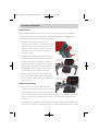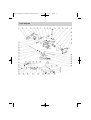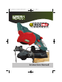
1
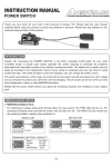
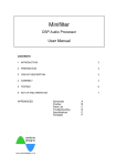
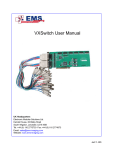
MAXI_operators booklet.qxd:Layout 1
12/9/13
17:34
Page 1
Chainsaw Sharpener
Instruction Manual
MAXI_operators booklet.qxd:Layout 1
12/9/13
17:34
Page 2
IMPORTANT!
Please familiarize yourself with the proper usage of the MAXI Mk2 by
reading this manual. Keep these instructions for future reference.
These operating instructions will make it easier for you to handle the
device and help avoid possible malfunction, damage or physical injury.
Safety Warnings and Precautions
1. Always wear protective clothing when operating the MAXI Mk2. Always wear safety
goggles and ear protection. Protective clothes, gloves and footwear are recommended
2. Always keep your work area clean and tidy, always use in well lit areas. Do not
expose to water. Do not use near flammable materials.
3. The MAXI Mk2 should be stored in a dry location to reduce the risk of rust. Always
keep the device clean and free of dust, metal debris and dirt at all times. Always lock
tools away and keep out of reach of children!
4. For your own safety do not use the MAXI Mk2 for a purpose for which it was not
intended. Do not sharpen damaged chains.
5. Never operate the MAXI Mk2 without the grinding wheel cover in place. Keep away
from the wheel when it is turning, and make sure no one is standing close, in the line
of the wheel rotation trajectory.
6. For your own safety always unplug the MAXI Mk2 when undertaking any inspections,
servicing, maintenance, cleaning or changing accessories.
7. Routinely check for damage before use. Do not operate if the machine if it does not
work correctly or has been dropped. Do not disassemble the MAXI Mk2 and do not try
to repair it yourself - contact your customer support!
8. Do not use a grinding wheel that is chipped, cracked, or worn. You can check if the
wheel has cracks not visible to the human eye by hanging it up by the central hole
and tapping it with a non-metal object (ie: screwdriver handle). If it is in good
condition it will produce a metallic sound. A dull sound indicates a crack or break.
MAXI_operators booklet.qxd:Layout 1
12/9/13
17:34
Page 3
Assembly of MAXI Mk2
Before First Use
Unpack the MAXI Mk2 and check all parts for any damage. Dispose of the packaging
materials and read the instruction manual carefully. The MAXI Mk2 is supplied partly
assembled, please assemble the machine as follows:
1. Remove the adjustment screw from the
accessory bag. Unscrew nut from the end of the
adjustment screw and feed through the motor
housing as shown right. Place the nut into the
Adjustment
screw
underside of the motor housing and begin to
tighten the screw.
2. Remove the large locking wheel from the chain
guide assembly and place the bolt end through
the hole in the unit base. Replace the locking
wheel on to the bolt and adjust to the required
angle before fully tightening. When installing
the MAXI Mk2 on to a work bench, make sure
that the locking screw is easily accessible.
3. Remove the grey plastic tension nut from the
end of the tension cable. Pull the cable through
the chain guide clamping piece and replace the
plastic tension nut.
Motor
housing
Chain guide
assembly
tension
cable
Base
Work surface
mounting holes
Work Surface Mounting
4. Place the unit base on to a solid, level work
surface. Ensure the base extends out far enough
over the edge so that the chain can hang freely
and you have easy access to the vice angle adjustment screw underneath. Mount the
base to the work surface through the two 9mm (1/4") mounting holes (bolts not
included).
5. The MAXI Mk2 is assembled and ready for use! The pre-installed grinding wheel is for
universal use. To replace a grinding wheel see “Grinding Wheel Replacement” section.
MAXI_operators booklet.qxd:Layout 1
Parts Diagram
12/9/13
17:34
Page 4
MAXI_operators booklet.qxd:Layout 1
12/9/13
17:34
Page 5
Parts List
1
2
3
4
5
6
7
8
9
10
11
12
13
14
15
16
17
18
19
20
21
22
23
24
25
26
27
28
ST4.2x14 Screw
Motor Cover
ST4.8x20 Screw
Side Handle
ST2.9x16 Screw
Circuitry Panel
Vanes
Inductance
Switch
Nut
Screw
Cushion
Cable
Motor Housing
Grinding Wheel Base
Grinding Wheel
Grind Lock Cap
Grinding Wheel Cover
ST2.9x12 Screw
ST4.2x10 Screw
Short Wire
Baffle
Circlip
Base
Lock Wheel
Rod
Torsion Spring
M8 Nut
29
30
31
32
33
34
35
36
37
38
39
40
41
42
43
44
45
46
47
48
49
50
51
52
53
54
55
Pin
Fuse
Fuse Sheath
Motor
ST5.5x22 Screw
Washer
Draw Spring
Screw
Nut
Cushion
M6 Nut
Fixed Base
13.2x16 Spring Pin
Back Clamping Piece
Star Wheel
Drive Rod
M5 Nut
ST5.5x20 Screw
Top Mat
Front Clamping Piece
Small Spring
ST4.8x10 Screw
M8x40 Screw
Snap Spring
Chain Stop
Steel Sleeve
Swing arm
MAXI_operators booklet.qxd:Layout 1
12/9/13
17:34
Page 6
Operation of MAXI Mk2
WARNING: Before connecting the machine to the mains power, make
sure the machine is switched ‘OFF’ to avoid unintended starting!
1. Clean the chain before sharpening. Inspect the chain for the most worn-out cutter
tooth and start sharpening with this tooth. The most worn-out tooth is important in
order to sharpen all other teeth to the same depth!
2. Lift up the chain stop, position the chain and secure the chain between the clamping
piece of the chain guide assembly. Fold down the chain stop and pull back the first
cutter tooth against the chain stop. Make sure the chain is between both guide boards
so that the chain can not tilt to the side.
3. Check the necessary filing angle according to the specifications for the chain. Adjust
the filing angle on the chain guide assembly to 25° - 35° or to the required angle and
tighten the locking screw.
4. Lower the motor housing so that the grinding wheel skims the chain tooth. Hold it in
this position while you tighten the screw so that the grinding wheel will only go
down to that point, fix this position with the locking screw.
5. Switch ‘ON’ the MAXI Mk2 by pressing firmly. Use the handle to bring the grinding
wheel down towards the chain tooth. As you bring down the motor housing the
tension cable will automatically clamp the chain between the metal chain
boards.
6. After sharpening one tooth, turn off the machine. Lift the motor housing, to release
the clamp boards, and move the chain so that the next link is positioned against the
chain stop. Mark the first cutter tooth with chalk, then sharpen every second tooth in
one direction. Repeat this process until you have sharpened all of the links set up for
this angle.
7. Change the cutting angle to 30° or to the required angle of the opposite direction of
the remaining chain cutter teeth.
MAXI_operators booklet.qxd:Layout 1
12/9/13
17:34
Page 7
Grinding Wheel Replacement
To avoid malfunction, damage or injury always use a suitable grinding wheel that is in
good condition. Do not use a grinding wheel that is chipped, cracked, or worn. You can
check if the wheel has cracks not visible to the human eye by hanging it up by the
central hole and tapping it with a non-metal object (ie: screwdriver handle). If it is in
good condition it will produce a metallic sound. A dull sound indicates a crack or break.
Make sure before carrying out any work on the MAXI Mk2 that the plug is disconnected
from the mains power.
Changing the Grinding Wheel
1. Switch off the machine and unplug from the main power source.
2. Raise the motor housing and lock it in the up position by tightening the nut. Remove
the grinding wheel protective cover by unscrewing the 4 retaining screws.
3. Hold the grinding wheel firmly with one hand and loosen the lock cap with the socket
wrench.
4. Remove the old grinding wheel and replace with a new one. Tighten the fixing nut
but do not over tighten - over tightening may cause the wheel to crack or break. Only
use grinding wheels with an outer diameter of 108mm and inner diameter of 23mm
(7/8"). The grinding speed of replacement grinding wheel must meet or exceed the
RPM rating of the machine.
5. Remount the grinding wheel protective cover onto the machine. Release the nut and
lower the motor housing. Never operate the MAXI Mk2 without the grinding wheel
cover in place. Keep away from the wheel when it is turning, and make sure no one
is standing close, in the line of the wheel rotation trajectory. If the grinding wheel
vibrates on start up, turn off the machine immediately and check that the grinding
wheel is mounted securely!
6 Never try to stop the grinding wheel with your hands, even if you are wearing safety
gloves. The grinding wheel will cut through gloves and your hand, causing serious
injury.
Replace the grinding wheel when it grinds down to a diameter of 75mm (3”).
MAXI_operators booklet.qxd:Layout 1
12/9/13
17:34
Page 8
Maintenance of the MAXI Mk2
Clean the ULTRA Mk2 from time to time with a dry paint brush or a brush in order to
remove any build up of grinding residues. Do not clean the ULTRA Mk2 with aggressive
detergents or aggressive chemicals.
Specifications
Nominal Voltage:
Nominal Power:
Frequency:
230V
85W
50Hz
Speed:
Cutting Angles:
Wheel Dimensions:
5,300 RPM
35° Left to Right
108mm Dia. x 3.2mm
108mm Dia. x 4.5mm
23mm
230mm (W) x 200mm (L) x 350mm (H)
2.1KG (including chain frame)
Shaft Diameter:
Overall Dimensions:
Weight:
Please Help Avoid Waste Materials
w
If you at some point intend to dispose of this item, then please keep
in mind that many of its components consist of valuable materials,
which can be recycled. Please do not discharge it in the rubbish bin,
but check with your local council for recycling facilities in your area.
Portek Limited, Bleaze Farm,
Old Hutton, Kendal. LA8 0LU.
United Kingdom.
Tel: +44(0)1539 722628
Email: [email protected]
Web: www.portek.co.uk