1
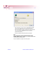
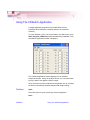
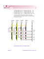
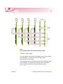
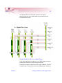
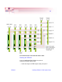
VXSwitch User Manual
UK Headquarters
Electronic Modular Solutions Ltd.
Kendal House, 20 Blaby Road
South Wigston, Leicester, LE18 4SB
Tel: +44 (0) 116 2775730 Fax: +44 (0) 116 2774973
Email: [email protected]
Website: www.ems-imaging.com
April 11, 2005
0
Contents
Introduction................................................................................................ 1
Models....................................................................................................... 1
Unpacking................................................................................................. 2
Installing Vision Switch............................................................................ 3
Video Inputs/Outputs................................................................................ 3
Software Installation VXSwitch-SA......................................................... 7
Using The VXSwitch Application............................................................ 8
Installing VXSwitch With The Vigilant Card........................................... 9
VXSwitch Jumper Links......................................................................... 14
Installing VXSwitch-V With Old Vigilant Cards..................................... 15
EMS Limited............................................................................................ 21
Index........................................................................................................ 23
VXSwitch
Contents
1
Introduction
Designed to be versatile and adaptable, the EMS VXSwitch provides
a complete 16x16 video crosspoint switch within a single PCI plug-in
card. Larger switch sizes are also possible by adding a second
VXSwitch card to produce either a 32 x 16 or 16 x 32 switch.
VXSwitch is supplied with driver software for Windows® NT,
Windows® 2000 and Windows® XP. A simple and intuitive Windows
application program is provided enabling users to control the
crosspoint switch or, for users who wish to control VXSwitch from their
own software, an SDK is also provided.
VXSwitch may also be used with the EMS Vigilant range of multiscreen graphics adapters. In this configuration VXSwitch is connected
to the Vigilant via inter-card ribbon cables, enabling the Vigilant video
overlay’s to select 1 of 16 possible video sources. A single VXSwitch
card will support up to four Vigilant graphics adapters.
Models
The EMS VXSwitch is available in 2 models:
VXSwitch-SA. A general purpose. stand alone video switch.
VXSwitch-V. This is used with the Vigilant-PRO/PLUS
Specification:
PCI level 2.2 compliant (3.3v/5v).
VXSwitch
Measurements
100 x 240mm.
Maximum Input level
2V rms.
Bandwidth
0 - 60Mhz (-3dB).
Crosstalk
-83dB at 20kHz.
THD
0.002% at 20kHz.
Gain
x1 into 75 ohms.
Power
1.5W
Switching Time
50 ns
Introduction
2
Unpacking
Your packing box should contain the following items:
• The VXSwitch plug-in card.
• Multi-way splitter cables.(2 for the VXSwitch-SA and 1 for the
VXSwitch-V).
• VSRC-set ribbon cables ( VXSwitch-V only)
• Installation CD-ROM.
Notes:
All plug-in cards are static sensitive and are packed in antistatic
materials. Please keep the card in its packaging until you are
ready to install.
We recommend that you do not discard the packing box until
you are completely satisfied with the VXSwitch, and it is fully
installed and working correctly. We also recommend that you
make note of the serial number of the card in a prominent place
before you plug the card into the computer. This should hasten
any query should you need to contact our Technical Support
Department. The serial number is displayed on the card and the
box label.
VXSwitch
Unpacking
3
Installing VXSwitch
Note:
You are likely to need a flat blade and a Phillips head screwdriver
for the installation so please ensure you have these to hand
before you begin.
• Power down your complete system (including peripherals) at the
PC and the main power supply.
• Disconnect all the cables connected to the PC, noting the
positions for correct reconnection after the VXSwitch is installed.
Carefully remove the cover from your PC.
• Locate an available PCI slot to install your VXSwitch. You may
need to remove the expansion slot cover and screw, please
retain these for future use.
• Holding the card firmly by its top edge at each end of the card’s
length, slide it into the slot.
• Using the retain screw, secure the bracket to the back panel.
• Replace the cover on your PC.
Video Inputs/
Outputs
The video signal is connected to the VXSwitch using a 16-way splitter
cable (provided). The cable consists of 16 BNC sockets
connected to a 26-way D plug.
The D plug should be connected to the Input socket on the back panel
of the VXSwitch. The Input socket is the top socket. Each BNC
socket is labelled to show the video input channel number. i e. 1 – 16.
The EMS VXSwitch-SA is a stand alone, general purpose video
switch. A second splitter cable is provided to channel the video outputs from the card. The sockets on the back panel of the card are
identical; therefore the same type of splitter cable is used for both
input and output.
The bottom D-connector located on the back panel is only used if
outputs from the VXSwitch-SA are to be monitored. This would not be
required if the VXSwitch-V is used.
VXSwitch
Installing VXSwitch
4
Jumper Links
There are a number of jumper links located on the face of the
VXSwitch card. Links 1 - 36 are user selectable.
The user links provide the following functions:
Links 1 to 16
Selects 75ohm termination for the video inputs. LK1, when fitted
terminates video input channel 1. The links 2 – 16 provide
termination for channels 2 – 16.
Links 17 to 32
Selects 75ohm termination for the video outputs. LK17 when fitted
terminates video output channel 1. The links 18 – 32 provide
termination for outputs 2 to 16.
Links 33 to 36
These links are always fitted when using a single VXSwitch card.
All cards are shipped with all links (1 – 36) fitted.
VXSwitch
Installing VXSwitch
5
Software Installation VXSwitch-SA
The VXSwitch drivers and software application for Windows® NT,
2000 and Windows® XP can be installed on your system using one of
the following methods:
The EMS CD supplied with the VXSwitch-SA card.
The EMS Web Site.
Before you commence software installation, ensure that you login with
administrator rights.
From the EMS CD
Insert the EMS CD into your CD ROM drive, from either the Run
menu option or using Explore to browse the CD, locate the setup
program, e.g. d:/VXSwitch/setup.exe.
Follow the Installation Wizard instructions as prompted.
From the EMS Web Site
Locate the latest version of the VXSwitch download file at
www.ems-imaging.com, click on the VXSwitch link and the following
dialog appears:
VXSwitch
Software Installation VXSwitch-SA
6
• When download is complete select the Save this file to disk
option and click OK and follow the download instructions.
• Once the download is complete, unzip the file, locate and double
click on the VXSwitch setup.exe file and the installation
process will commence.
• Follow the Installation Wizard instructions as prompted.
Note:
When the application installs on Windows® 2000, the New
Hardware Wizard will run. Dismiss the Hardware Wizard and
continue with the setup as above.
Once the installation is complete, reboot the system.
VXSwitch
Software Installation VXSwitch-SA
7
Using The VXSwitch Application
A simple application programme is provided with the Vision
Switch-SA which allows the crosspoint switch to be controlled
manually.
To open VXSwitch, select the icon located in the Start menu group:
Start | Program | VXSwitch that was created during installation, once
selected the application window is displayed.
The VXSwitch application window displays a list of available
Outputs and Inputs. Using the up/down arrows, you can select which
input you want to set against a specific output.
Once a selection has been made and a configuration set up, checking
the On box immediately initialises that particular Output setting.
File Menu
Open...
Select this option to open a previously saved configuration.
Save...
VXSwitch
Using The VXSwitch Application
8
Select this option to save any changes to a configuration. This option
is only activated if a previously saved configuration has been opened
and amended.
Save As...
Select this option to save a newly created configuration.
Exit
Select this option to close down the VXSwitch application.
Help Menu
VXSwitch
Displays details of the software version number and copyright
information
Using The VXSwitch Application
9
Installing VXSwitch With The Vigilant Card
The EMS VXSwitch is connected to the Vigilant cards via inter-card
ribbon cables, enabling the Vigilant video overlays to select 1 of 16
possible video sources. The VXSwitch supports up to four Vigilant
cards.
• Install and configure all Vigilant cards in the system, carefully
following the Vigilant installation instructions. Ensure that your
multi-screen system is working correctly before installing the
VXSwitch.
• Install the VXSwitch carefully following the installation
instructions provided.
• Once the VXSwitch is installed it can be connected to the Vigilant
cards.
You will need to determine the ordering of the Vigilant cards to enable
the correct connection. The example below displays four Vigilant
cards
configured as a 4 x 4 monitor video wall. The ordering in this example
is the Vigilant (1), the Master Vigilant card always drives the first four
screens, in this case the top four. The second Vigilant drives the next
four, and so on. Count the screens starting from the top left of the
video wall and then across from left to right:
Once the order of the Vigilant cards has be determined, connect the
ribbon cables as follows:
VXSwitch
Installing VXSwitch With The Vigilant Card
10
1st Vigilant (Master) (J3)
2nd Vigilant (Slave) (J3)
3rd Vigilant (Slave) (J3)
4th Vigilant (Slave) (J3)
To VXSwitch (Output 1-4)
(J6)
To VXSwitch (Output 5-8)
(J7)
To VXSwitch (Output 9-12) (J8)
To VXSwitch (Output 13-16) (J9)
The diagram below is for illustration purposes only and the
particular sequence of the Vigilant cards in your machine will not
necessarily be the same.
Using VXSwitch with 5 or 6 Vigilant Cards
VXSwitch
Installing VXSwitch With The Vigilant Card
11
If your video wall system is made up of 5 or 6 EMS Vigilant cards then
installing two VXSwitch cards supports them all.
Follow the procedures outlined above for a single VXSwitch. This first
VXSwitch card is connected to the first four Vigilant cards. Follow the
instructions below to install the second VXSwitch:
• Remove the jumper links 1 to 16 and link 33 from the second
VXSwitch card.
• Insert the second VXSwitch into a PCI slot adjacent to the first
VXSwitch.
• Fit two short ribbon cables to connect both VXSwitch cards; connect J4 to J4 (Inputs 1-8) and J5 to J5 (Inputs 8-16)
• Fit ribbon cables from the Vigilant 5 and 6 to the second
VXSwitch as follows:
5th Vigilant (J3)
6th Vigilant (J3)
VXSwitch
To
To
2nd Video Switch (Output 1-4) (J6)
2nd Video Switch (Output 5-8) (J7)
Installing VXSwitch With The Vigilant Card
12
To configure VXSwitch cards and Vigilant cards to produce 32 inputs
and 16 outputs the connections should be as follows:
VXSwitch
Installing VXSwitch With The Vigilant Card
13
Note:
Care should be taken not to twist the ribbon cables.
VXSwitch -Video Inputs
The video signal is connected to the VXSwitch using a 16-way splitter
cable (provided). The cable consists of 16 BNC sockets
connected to a 26-way D plug.
The D plug should be connected to the Input socket on the back panel
of the VXSwitch. The Input socket is the top socket. Each BNC
socket is labelled to show the video input channel number.
i e. 1 – 16.
VXSwitch
Installing VXSwitch With The Vigilant Card
14
The bottom D-connector located on the back panel is only used if
outputs from the VXSwitch are to be monitored, normally this would
not be required if the VXSwitch is used in conjunction with Vigilant
cards.
The EMS VXSwitch can also be used as a stand alone,
general purpose video switch. When used this way a second
splitter cable is required to channel the video outputs from the
VXSwitch. The sockets on the back panel of the card are identical;
therefore the same type of splitter cable is used for both.
VisionSwitch
Jumper
Links
There are a number of jumper links located on the face of the
VXSwitch card. Links 1 – 36 are user selectable.
The user links provide the following functions:
• Links 1 to 16
Selects 75ohm termination for the video inputs. LK1, when
fitted terminates video input channel 1. The links 2 – 16
provide termination for channels 2 – 16.
• Links 17 to 32
Selects 75ohm termination for the video outputs. LK17 when
fitted terminates video output channel 1. The links 18 – 32 provide termination for outputs 2 to 16.
• Links 33 to 36
These links are always fitted when using a single VXSwitch card.
All cards are shipped with all links (1 – 36) fitted.
VXSwitch
Installing VXSwitch With The Vigilant Card
15
Installing VXSwitch-V With Vigilant Cards
The EMS VXSwitch is connected to the Vigilant cards via inter-card
ribbon cables, (VSRC-set) enabling the Vigilant video
overlays to select 1 of 16 possible video sources. The VXSwitch supports up to four Vigilant 4 VW cards
• Install and configure all Vigilant 4VW cards in the system
carefully following the Vigilant installation instructions. Ensure
that your multi-screen system is working correctly before
installing the VXSwitch.
• Once the VXSwitch is installed it can be connected to the Vigilant
cards.
• You will need to determine the ordering of the Vigilant cards to
enable the correct connection. The example below displays four
Vigilant cards configured as a 4 x 4 monitor video wall. The
ordering in this example is the Vigilant 1(the Master Vigilant card)
always drives the first 4 screens, in this case the top four. The
second Vigilant drives the next four, and so on. Count the
screens starting from the top left of the video wall and then
across from left to right:
Once the order of the Vigilant cards has be determined connect the
ribbon cables as follows:
1st Vigilant (Master) (J3)
2nd Vigilant (Slave) (J3)
3rd Vigilant (Slave) (J3)
4th Vigilant (Slave) (J3)
VXSwitch
To VXSwitch (Output 1-4)
(J6)
To VXSwitch (Output 5-8)
(J7)
To VXSwitch (Output 9-12) (J8)
To VXSwitch (Output 13-16) (J9)
Installing VXSwitch-V With Vigilant Cards
16
The diagram below is for illustration purposes only and the
particular sequence of the Vigilant cards in your machine will not
necessarily be the same.
Using VXSwitch-V with 5 or 6 Vigilant Cards
If your video wall system is made up of 5 or 6 EMS Vigilant cards then
installing two VXSwitch-V cards can support them all.
Follow the procedures outlined above for a single VXSwitch. This first
VXSwitch card is connected to the first four Vigilant cards. Follow the
VXSwitch
Installing VXSwitch-V With Vigilant Cards
17
instructions below to install the second VXSwitch:
• Remove the Jumper Links 1 to 16 and link 33 from the second
VXSwitch card.
• Remove the jumper links 1 to 16 and link 33 from the second
VXSwitch card.
• Insert the second VXSwitch into a PCI slot adjacent to the first
VXSwitch.
• Fit two short ribbon cables to connect both VXSwitch cards; connect J4 to J4 (Inputs 1-8) and J5 to J5 (Inputs 8-16)
• Fit ribbon cables from the Vigilant 5 and 6 to the second VXSwitch as follows:
• 5th Vigilant (J3) To 2nd Video Switch (Output 1-4) (J6)
6th Vigilant (J3) To 2nd Video Switch (Output 5-8) (J7)
VXSwitch
Installing VXSwitch-V With Vigilant Cards
18
Note:
Care should be taken not to twist the ribbon cables.
Selecting the VXSwitch
If you are installing the EMS VXSwitch to operate in
conjunction with EMS Vigilant cards:
• Install and configure the EMS Vigilant card(s) as required.
VXSwitch
Installing VXSwitch-V With Vigilant Cards
19
• The VXSwitch-V drivers are installed automatically with the Vigilant/iH drivers.
• Open the Video Overlay sheet in the Display Properties dialog by
clicking the right mouse button anywhere on the desktop, select
properties from the displayed menu select Settings and then
Advanced then the Video Overlay tab. Alternatively, go to Start/
Settings/Control Panel/Display and select the Video Overlay
tab. The following dialog is displayed:
Use the down arrow to display a list of available Video Switches.
VXSwitch
Installing VXSwitch-V With Vigilant Cards
20
• Select the VXSwitch and click on Setup...
• The system will automatically test the setup of VXSwitch and display a message box giving details of the test result.
• Click on Apply.
VXSwitch
Installing VXSwitch-V With Vigilant Cards
21
EMS Limited
Electronic Modular Solutions Ltd., founded in 1992 initially specialized
in the manufacturing of VMEbus based CPU boards, graphics and
peripheral products with distribution and integration of VMEbus imaging products.
Since 1997, the company has diversified and now offers high performance PCIbus based imaging products. Our imaging products have
been successfully implemented for industrial, medical, military,
research and scientific use.
EMS offers a reliable and flexible range of frame grabbers, video processors, cameras and auxiliary products. These can be integrated
into various applications such as image analysis, machine vision,
robotics, radar, ultrasound, sonar, security/surveillance, video conferencing, presentation systems and archiving etc...
EMS products developed and tested by engineers skilled in delivering
high performance and quality solutions that ensure success in the
most challenging circumstances. As new technology advances, so we
at EMS improve the performance and functionality of both our hardware and software to give our customers more. Following a continuous development program, we pride ourselves on our support and
responsive nature towards all our customers and their changing
needs. As more sophisticated equipment and techniques become
readily available, so we are there to exploit the power and potential
that this technology presents.
Technical Support
Registered Users can access our technical support line via fax ,
email or by using the Problem Report form on the support page on the
EMS Web Site,usually with a response within 24 hours (excluding
weekends).
Via Email: Send an email to [email protected] with as
much information about your system as possible. To enable a swift
response we need to know the following details:
VXSwitch
EMS Limited
22
• Specification of the PC - including processor speed
• Operating System
• Application Software
• EMS Hardware / Software
• The exact nature of the problem - and please be as specific as
possible.
Please quote version and revision numbers of hardware and software
in use wherever possible.
Copyright Statement
© EMS Ltd., England, 2004
EMS Limited claims copyright on this documentation. No part of this
documentation may be reproduced, released, disclosed, stored in any
electronic format, or used in whole or in part for any purpose other
than stated herein without the express permission of EMS Limited.
Whilst every effort is made to ensure that the information contained in
this on-line help is correct, EMS Limited make no representations or
warranties with respect to the contents thereof, and do not accept liability for any errors or omissions. EMS reserves the right to change
specification without prior notice and cannot assume
responsibility for the use made of the information supplied. All
registered trademarks used within this documentation are
acknowledged by EMS Limited.
UK Headquarters
Electronic Modular Solutions Ltd.
Kendal House, 20 Blaby Road
South Wigston, Leicester, LE18 4SB
Tel: +44 (0) 116 2775730 Fax: +44 (0) 116 2774973
Email [email protected]
www.ems-imaging.com
VXSwitch
EMS Limited
23
Index
A
application programme 7
B
Bandwidth 1
BNC socket 4
C
Copyright Statement 22
Crosstalk 1
D
Display Properties dialog 19
E
EMS CD 5
EMS Limited 21
Email 21
Exit 8
F
File Menu 8
H
Help Menu 6
I
Inputs 3
Installing 3
Installing With Vigilant Cards 15
J
Jumper Links 4
jumper links 11, 14
VXSwitch
Index
24
L
Links 1 - 36 4
M
Maximum Input level 1
Measurements 1
Models 1
Multi-way splitter cables 3
O
Open... 8
Outputs 3
S
Save As.. 7
Save... 7
Software Installation 5
Specification 1
stand alone 3
T
Technical Support 21
U
UK Headquarters 22
Unpacking 2
Using VXSwitch 8
V
Via Fax 22
Video Inputs 14
Video Overlay sheet 20
video wall system 11
VXSwitch setup.exe 7
VXSwitch-V. 1
VXSwitch-SA 1
VXSwitch
Index