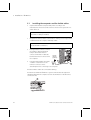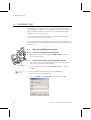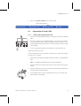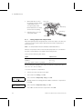
1
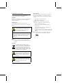
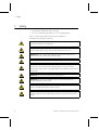
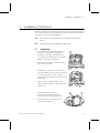
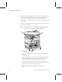
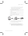
GE Healthcare
ÄKTAmicro™
Installation Guide
2
ÄKTAmicro Installation Guide 28-9490-95 Edition AB
Important user information
All users must read this entire manual to fully
understand the safe use of ÄKTAmicro.
Important!
ÄKTAmicro is intended for research use only, and should
not be used in any clinical or in vitro procedures for
diagnostic purposes.
Safety notices
This manual contains warnings and cautions
concerning the safe use of the product. See definitions
below.
WARNING! The WARNING symbol and
notice highlight instructions that must be
followed to avoid personal injury. Do not
proceed until all stated conditions are
clearly understood and met.
CAUTION! The CAUTION notice highlights
instructions that must be followed to avoid damage
to the product or other equipment. Do not proceed
until all stated conditions are met and clearly
understood.
Notes
Note: A Note is used to indicate information that is
important for trouble-free and optimal use of the
product.
Recycling
This symbol indicates that the waste of
electrical and electronic equipment must not
be disposed as unsorted municipal waste
and must be collected separately. Please
contact an authorized representative of the
manufacturer for information concerning the
decommissioning of equipment.
WARNING! This is a Class A product. In a
domestic environment, it might cause
radio interference, in which case the user
might be required to take appropriate
measures.
WARNING! All repairs should be done by
personnel authorized by GE Healthcare.
Do not open any covers or replace parts
unless specifically stated in the
instructions.
CE-certification
This product complies with the European directives
listed below, by fulfilling corresponding standards.
A copy of the Declaration of Conformity is available on
request.
•
73/23/EEC, Low Voltage Directive
•
89/336/EEC, EMC Directive
The CE logo and corresponding declaration of
conformity, is valid for the instrument when it is:
–
used as a stand-alone unit, or
–
connected to other CE-marked GE Healthcare
instruments, or
–
connected to other products recommended or
described in this manual, and
–
used in the same state as it was delivered from GE
Healthcare except for alterations described in this
manual.
Note: The Declaration of conformity is valid only for
systems that are marked with the CE logo:
Contents
1
About this installation guide..................................... ......... 7
2
Safety ............................................................................ ......... 8
3
Pre-requisites............................................................... ......... 9
4
Installation overview .................................................. ......... 10
5
Installation of ÄKTAmicro .......................................... ......... 11
5.1
5.2
5.3
6
Unpacking .................................................................................... . 11
Installing the computer and the UniNet cables ................... . 14
Connecting the mains cables ................................................... . 15
Installation test ........................................................... ......... 16
6.1
Start up the ÄKTAmicro system .............................................. . 16
6.1.1 Start up the ÄKTAmicro separation unit......................................... 16
6.1.2 Start up the computer and the UNICORN software .................. 16
6.2
Preparation of Pump P-905 ...................................................... . 17
6.2.1 Priming and purging Pump P-905 .................................................... 17
6.2.2 Setting compression compensation................................................. 18
6.2.3 Testing pressure stability ...................................................................... 19
6.3
6.4
Running the installation test method .................................... . 20
Evaluating the installation test results .................................. . 23
6.4.1 Automatic evaluation.............................................................................. 23
6.4.2 Manual evaluation ................................................................................... 23
6.5
Correcting faulty evaluation results ...................................... . 25
6.5.1 Faulty gradient .......................................................................................... 25
6.5.2 Faulty step response............................................................................... 25
7
Test record.................................................................... ......... 26
7.1
7.2
7.3
Gradient test result .................................................................... . 26
Step response test result .......................................................... . 26
UV response test result ............................................................. . 26
8
Installation record....................................................... ......... 27
9
Registration form ........................................................ ......... 29
10 Components ................................................................. ......... 30
ÄKTAmicro Installation Guide 28-9490-95 AB
5
6
ÄKTAmicro Installation Guide 28-9490-95 Edition AB
About this installation guide 1
1
About this installation guide
ÄKTAmicro is assembled and fully tested before shipping.
For safe transportation, however, some components have been secured and
thus need to be detached before the system can be tested and used.
Cables, capillaries, accessories, etc. are enclosed in paper boxes or in Box-900
located at the top of the instrument pile.
This guide describes how to install ÄKTAmicro. The guide is divided into two
parts; one describing the installation and one describing how to run the
installation test. After the installation procedure has been performed, your
ÄKTAmicro is ready for purification work.
For full details of specifications, methods, maintenance etc., refer to the
respective User Manuals and Instructions.
ÄKTAmicro Installation Guide 28-9490-95 Edition AB
7
2 Safety
2
Safety
•
The system is designed for indoor use only.
•
Do not use in a dusty atmosphere or close to spraying water.
Refer to Technical Specifications in the System Manual for
detailed environmental pre-requisites.
WARNING! The ÄKTAmicro system operates under high pressure. Eye
protection must be worn at all times.
WARNING! The individual modules must not be opened by the user. They
contain high voltage circuits that can give a lethal electric shock.
WARNING! Monitor UV-900 uses high intensity ultra-violet light. Do not
disconnect the optical unit while the lamp is ON.
WARNING! ÄKTAmicro must be connected to a grounded mains socket.
WARNING! There must always be a sample loop connected to ports 2 and 6 of
the injection valve. This prevents liquid spraying out of the ports when
switching the valve, which is especially dangerous if hazardous chemicals are
being used.
WARNING! Two people are required to lift the system.
WARNING! Never block the flowpath outlet, since this will create overpressure and may result in injury.
WARNING! Only spare parts approved or supplied by GE Healthcare may be
used for maintaining and servicing the system.
WARNING! Never place waste containers on the top of the system. If they
become full and overflow, liquid may penetrate the system causing a shortcircuit.
8
ÄKTAmicro Installation Guide 28-9490-95 Edition AB
Pre-requisites 3
3
Pre-requisites
WARNING! ÄKTAmicro must be connected to a grounded mains socket.
•
Two people are recommended to lift ÄKTAmicro onto the working bench.
•
To install ÄKTAmicro, a working area of about 200 × 80 cm is required.
•
ÄKTAmicro requires 100 to120/220 to 240 VAC, 50/60 Hz electrical supply
with safety grounding.
•
Cutting pliers are recommended for cutting plastic straps.
•
A waste flask.
IMPORTANT! Before using ÄKTAmicro equipment, read all the safety
information in section 1.2 in ÄKTAmicro System Manual.
The installation test requires the following solutions:
•
200 ml of distilled water for priming and purging the pump.
•
100 ml of 0.4% acetone in distilled water.
•
100 ml of 20% ethanol in distilled water.
ÄKTAmicro Installation Guide 28-9490-95 Edition AB
9
4 Installation overview
4
10
Installation overview
•
Unpack ÄKTAmicro page 11
•
Detach secured items, and install items enclosed page 12
•
Unpack and install the computer page 14
•
Connect mains power cabling page 14
•
Connect UniNet 1 data communication chain cabling page 14
•
Complete the first two sections of the installation record page 27
•
Prepare ÄKTAmicro for the installation test page 16
•
Run the installation test method page 20
•
Evaluate the gradient page 24
•
Evaluate the step response page 24
•
Evaluate the UV response page 25
•
Complete the test record page 26
•
Complete the registration form page 29
•
Complete the final section of the installation record page 27
•
Store photocopies of all records and forms in the
System Logbook.
•
Store the Installation Guide in the User Manual box.
ÄKTAmicro Installation Guide 28-9490-95 Edition AB
Installation of ÄKTAmicro 5
5
Installation of ÄKTAmicro
Begin by creating a clean and dry working area of 200 × 80 cm that allows easy
access. Then follow the step-by-step instructions below and fill in the installation
record as you go along, see page page 27.
Note: Some components are packed in Box-900, located at the top of the
system.
Note:
5.1
Some packing lists are included in the paper boxes.
Unpacking
1
After having removed the cardboard hood,
check the contents against the attached
packing list. Check also all included boxes.
Store all the enclosed paper boxes and plastic
bags in a convenient nearby place.
2
Release and remove the red strap (1) holding
the system to the pallet.
3
Lift ÄKTAmicro onto the work area using the
four strap handles (2). Two people are required
to lift the system. Do not raise to upright
position yet. Lay the system on the same side as
on the pallet.
4
Release the two red straps with the strap
handles. Allow the straps to remain taped to the
plastic cover.
5
Pull back the plastic cover (3) to
uncover the swivel platform (4) and
raise the system to an upright position.
6
Remove the plastic cover with the red
straps from the system.
ÄKTAmicro Installation Guide 28-9490-95 Edition AB
1
2
4
3
11
5 Installation of ÄKTAmicro
7
Save all the original packing material. If, for any reason, the equipment has
to be repacked, for transportation or otherwise, it is important that the
system can be safely packed using the original packing material.
8
Turn ÄKTAmicro on its swivel platform to access the fluid component side
of the system.
9
Detach the following items by cutting straps and removing red tape. Also
remove the desiccant bags.
Note: Use cutting pliers. Be careful not to cut any capillaries by accident.
Make sure not to lose any of the capillary marking tags.
*
*
here and
* Cut
remove foam
12
Cut here
•
Plastic hood covering the Injection Valve and the Mixer, including the
PEEK tubings.
•
Injection Valve INV-917, located at the top left side. Detach the valve
from the attachment bracket to remove the protective foam, and
reposition the valve to the slot in the attachment bracket.
•
Mixer M-925, located next to INV-917. Detach the Mixer from the
attachment bracket to remove the protective foam, and reposition the
mixer to the same slot in the attachment bracket.
•
SV-903A and SV-903B, located between the pump heads on
P-905.
ÄKTAmicro Installation Guide 28-9490-95 Edition AB
Installation of ÄKTAmicro 5
•
UV cell cover, located above the UV flow cell. Remove the red tapes.
•
Capillary loops. Remove the red tape holding the capillary loops
attached to INV-917 (waste capillaries W1 and W2).
10 Place the waste tubings W1 and W2 in waste bottles and place the bottles
in front of ÄKTAmicro, or wherever convenient.
11 Unpack the inlet tubing fixed in a plastic bag taped to the buffer tray on top
of Box-900.
12 Make sure all items are securely fitted, and that no capillary connection has
worked loose, or been tangled.
13 Attach the column holder enclosed in Box-900 above the UV cell. Select a
slot to suite the height of the column to be used.
Should the cover over the UV cell compartment come loose, it is refitted in the
following way:
1
The cover is a simple push fit onto the cell holder. Two small lugs on the
cover locate in holes at the front and rear of the cell holder.
2
The cover is then lowered over the cell holder.
Note: You can select a fraction collector, an autosampler or an MS-unit as
optional components. Installing the fraction collector and the
autosampler is described in the ÄKTAmicro Optional Configurations User
Manual. The MS must be installed by authorized service personnel.
ÄKTAmicro Installation Guide 28-9490-95 Edition AB
13
5 Installation of ÄKTAmicro
5.2
1
Installing the computer and the UniNet cables
Unpack and install the computer and printer according to the
manufacturer’s instructions. Place them to the left of the system. Do not
switch them on!
CAUTION! The mains power to ÄKTAmicro must be switched OFF before
the UniNet 1 cabling is installed.
2
Complete the UniNet 1 data communication chain by connecting a UniNet
1 cable between the computer and Pump P-905.
CAUTION! The UniNet connection to the computer MUST be made to
the board with four LEDs (37).
3
4
If using a fraction collector, connect
the UniNet 1 cable (35) between
Pump P-905 and the fraction
collector, and UniNet 1 cable (36)
between the fraction collector and
the computer.
Fraction
collector
(optional)
If using an autosampler, the UniNet
1 cable is routed via one of the
36
UniNet 1 connectors in the
autosampler before connecting to the computer.
35
All other UniNet 1 cables are connected at delivery.
An MS-unit used with the ÄKTAmicro system communicates through serial
standard cables with the computer. See the documentation of the MS-unit to
connect the unit.
37
14
ÄKTAmicro Installation Guide 28-9490-95 Edition AB
Installation of ÄKTAmicro 5
5.3
Connecting the mains cables
WARNING! ÄKTAmicro must be connected to a grounded mains socket.
5
Connect a mains cable (39)
supplied between ÄKTAmicro
and a properly grounded mains
socket. Do not switch on!
Fraction
collector
(optional)
39
38
38
6
If using a fraction collector,
connect a mains cable supplied (38)
between the fraction collector and
a mains socket at the rear of
ÄKTAmicro.
7
If using an autosampler, connect a
mains cable between the
autosampler and a mains socket at
the rear of ÄKTAmicro.
8
Complete the two first sections of
the Installation record on page
page 27.
To
fraction
collector
To
autosampler
To mains socket
The installation phase of ÄKTAmicro is now completed!
ÄKTAmicro Installation Guide 28-9490-95 Edition AB
15
6 Installation test
6
Installation test
The installation test checks the function of the solvent delivery and the UV
monitoring system of ÄKTAmicro. The installation test can also be used at any
time to check the condition of the system, e.g. for calibrating the system
regularly or after a prolonged stop.
Correct gradient formation is tested by producing a linear gradient and
a series of concentration steps of acetone.
Correct UV monitoring is tested by monitoring the acetone concentration at
265, 254 and 280 nm and calculating the absorbance ratios 265/254 nm and
265/280 nm.
6.1
Start up the ÄKTAmicro system
6.1.1
Start up the ÄKTAmicro separation unit
1
Switch on the separation unit using the ON/OFF switch located to the
left on the base platform.
6.1.2
ON/OFF switch
16
Start up the computer and the UNICORN software
1
Switch on the computer, the display and the printer according to the
instructions in the manufacturer manuals.
2
Log into Windows™ by first pressing Ctrl-Alt-Del, and then clicking
on OK.
3
When the Windows desktop appears, start UNICORN™ by
double-clicking on the UNICORN icon.
4
Select user default and enter default as password. Click on OK.
ÄKTAmicro Installation Guide 28-9490-95 Edition AB
Installation test 6
5
Click on the System Control button in the task bar.
System Control Button
1
A
2
B
6.2
Preparation of Pump P-905
6.2.1
Priming and purging Pump P-905
1
Immerse the rinsing tubing in a flask (1) containing 20% ethanol in distilled
water.
2
Connect a syringe to the rinsing tubing that is connected to the underside
(2) of the left pump head on pump A. Slowly draw rinsing solution to the
syringe. When rinsing solution starts to enter the syringe, continue to draw
a few milliliters.
3
Loosen the syringe and immerse the tubing in the rinsing solution (1).
Purge Pump P-905 as follows:
To turn the purge valve a 10 mm spanner is required. The torque used to tighten
the valve is 1.2 to 1.8 Nm.
1
Immerse the inlet tubing of all pump modules, with filters, in a distilled water
flask.
Note: Never place the flask below the level of the pump inlet.
2
Connect a male Luer syringe of about 30 ml to the open end of the purge
tubing.
3
Connect a male Luer connector at the other end of the purge tubing to the
left purge valve at pump module A.
4
Turn the purge valve counter clockwise half a turn to open it and slowly
draw eluent into the syringe.
ÄKTAmicro Installation Guide 28-9490-95 Edition AB
17
6 Installation test
5
6
When fluid starts to enter
the syringe continue to draw
a few milliliters before
closing the purge valve.
Check that there is no visible
air left in the inlet tubing.
Purge valve
Outlet tubing
Purge tubing
Repeat steps 3 to 5 for the
other pump heads.
6.2.2
Setting compression compensation
When running Pump P-905 at high pressures, flow losses might occur due to the
compression of the eluent. Pump P-905 has functions that compensate for
these flow losses.
Note: The compensation functions should be activated at all times.
With the compensation function activated, the pump takes into consideration
the given compressibility for the liquid, at the actual pressure.
Some common values are given below:
Liquid
Value in Pa-1
Water
Methanol
Most other organic solvents, e.g. ethanol
4.6 × 10⁻¹⁰
12.1 × 10⁻¹⁰
11.0 × 10⁻¹⁰
Before starting the installation test, make sure that the compensation value is
set to 4.6 × 10⁻¹⁰ Pa-1 (for water).
To set the compression compensation:
Setup Compr. comp
(off)
off on
Setup Start comp.
(off)
off on
18
1
Turn the front selection Dial on the pump.
2
Select main menu Setup, press OK.
3
Select sub menu Setup Compr. comp, press OK.
4
Change numbers accordingly and select On to activate the compensation.
Press OK.
5
Select sub menu Setup Start comp, press OK.
6
Select On to activate the start compensation. Press OK.
ÄKTAmicro Installation Guide 28-9490-95 Edition AB
Installation test 6
Setup Compr. value A
(4.6E-10) 4.6
Setup Compr. value B
(4.6E-10) 4.6
7
Select sub menu Setup Compr. value A, press OK.
8
Enter compensation value 4.6 × 10⁻¹⁰ Pa-1 for pump module A.
9
Select sub menu Setup Compr. value B, press OK.
10 Enter compensation value 4.6 × 10⁻¹⁰ Pa-1 for pump module B.
11 Press ESC, ESC -> END
6.2.3
Testing pressure stability
Perform a pressure test to establish that all air has disappeared from the pump
heads. Perform as follows:
1
Connect a capillary between port 1 on the Injection valve to the inlet of the
UV optical unit.
2
Run 0.2 ml/min at 0% B (distilled water). Check on the pump display that the
pressure reading is stable (variation < ±5%).
3
Run 0.2 ml/min at 100% B (distilled water). Check on the pump display that
the pressure reading is stable (variation < ±5%).
4
Proceed to step 5 if the pressure is stable. If not, consult the Pump P-905
User Manual for trouble-shooting instructions.
5
Click on END.
6
Transfer the inlet tubing B1 into a flask containing 100 ml of 0.4% acetone
in distilled water.
Installation Test Method Guide
Buffer A:
Distilled water
Buffer B:
0.4% acetone in distilled water
Test flow rate:
1 ml/min
Test run time:
Approximately 30 minutes
ÄKTAmicro Installation Guide 28-9490-95 Edition AB
19
6 Installation test
6.3
20
Running the installation test method
1
In UNICORN Manager module, select File:Printer Setup.... Select the
appropriate printer from the list and select Landscape. Then click OK to
acknowledge the printer chosen.
2
In System Control module, select File:Instant Run. The Instant Run
window opens.
3
Select the appropriate system from the For system list.
4
Click Run. The Method Wizard is started.
5
Select Installation_Test from the Main Selection list and click Run.
ÄKTAmicro Installation Guide 28-9490-95 Edition AB
Installation test 6
6
Click Next in the Evaluation Procedures window.
7
Click Next in the Method Information window.
8
Make sure that the compression compensation value for water,
4.6 × 10⁻¹⁰ Pa-1, is set in Pump P-905 (refer to section 6.2.2 Setting
compression compensation).
9
Click START in the Result Name window to start the installation test.
The progress of the test is monitored in the System Control module. The
installation test run time is approximately 30 min.
When the test is finished, the printer automatically prints the chromatogram
and the test results.
100%
95%
70%
30%
5%
Gradient
result
ÄKTAmicro Installation Guide 28-9490-95 Edition AB
0%
Step response result
21
6 Installation test
Customizing the Curves pane
To customize the Curves pane:
1
Right-click in the Curves pane and select Properties.
2
Click the Curves tab.
3
Select the following curves to be displayed:
•
UV
•
Conc
Clear all other curves. Click OK.
22
ÄKTAmicro Installation Guide 28-9490-95 Edition AB
Installation test 6
6.4
Evaluating the installation test results
6.4.1
Automatic evaluation
The system automatically prints out the test result when the test is finished. The
print-out consists of a chromatogram and an evaluation of the test result.
•
If the gradient test result is OK, the print-out says
“Gradient linearity accepted”.
•
If the step response test result is OK, the print-out says
“Step response accepted”.
•
If the UV response test result is OK, the print-out says
“UV response accepted”.
If any of the evaluated values falls outside the specified range, go to section 6.5
Correcting faulty evaluation results.
6.4.2
Manual evaluation
If your chromatography system differs from the standard configuration, for
example, if optional components have been installed, the automatic evaluation
may not give a reliable result. A manual evaluation is required.
1
Minimize the run data window to access the Main menu.
2
Click on
in the results window and then double-click on the
Installation Test01 icon to open the result file.
3
Maximize the chromatogram window by clicking on
corner.
4
Click in the Curves window with the right mouse button and select
Properties.
5
Click on the Curves tab and select the following curves to displayed:
6
•
Installation Test01:1_UV1_265nm@01,SMTH
•
Installation Test01:1_UV2_254nm@02,SMTH
•
Installation Test01:1_UV3_280nm@03,SMTH
•
Installation Test01:1_Conc
in the upper right
Press OK.
ÄKTAmicro Installation Guide 28-9490-95 Edition AB
23
6 Installation test
7
Click on the UV curve name in the upper left corner of the chromatogram
window and read the absorbance for the steps corresponding to
Installation Test01:1_UV1_265nm@01,SMTH. Right click in the Curves
window and click on the “Marker”. Move the vertical marker to the constant
section of each plateau by dragging it. Enter the absorbance values (in
mAU) in column 2 in the Step response table of the Test record (see page 26),
leaving out the decimals.
8
Read the absorbance for the plateaus corresponding to 0% B and 100% B
for the curves (click on the curve name to change the curve reading):
•
Installation Test01:1_UV1_265nm@01,SMTH
•
Installation Test01:1_UV2_254nm@02,SMTH
•
Installation Test01:1_UV3_280nm@03,SMTH
Enter the values in column 2 in the UV response table of the Test record (see
page 26).
9
Click on Print under File to print out the chromatogram.
Evaluating the gradient
Place a ruler along the gradient part of curve
Installation Test01:1_UV1_265nm@01,SMTH in the printed report.
The curve should be linear between 10% B and 90% B and void of
discontinuities.
Evaluating the step response
Calculate the relative adsorption plateau heights for curve
Installation Test01:1_UV1_265nm@01,SMTH as follows:
1
Subtract the base line value (0% B) from each of the values in column 2 in
the Step response table of the Test record (see page 26) and enter the
results in column 3.
2
Divide each value in column 3 by the base line corrected value
corresponding to 100% B, multiply by 100 and enter the results in column 4.
The values of column 4 should all fall within the intervals given in column 5.
24
ÄKTAmicro Installation Guide 28-9490-95 Edition AB
Installation test 6
Evaluating the UV response
Calculate the UV response ratios in the following way:
1
Subtract the base line values (0% B) corresponding to each UV curve from
the values in column 2 of the UV response table of the Test record (see page
26) and enter the results in column 3.
2
Calculate the absorbance ratios 265 nm/254 nm and
265 nm/280 nm using the values of column 3 and enter the results in
column 4.
The ratios obtained should all fall within the intervals given in
column 5.
6.5
Correcting faulty evaluation results
Should any of the evaluated values fall outside the specified range, proceed as
follows:
If the system differs from the standard configuration, evaluate the result
manually.
If the faulty evaluation result remains, continue below.
6.5.1
Faulty gradient
•
The mixer is faulty.
•
Disturbances – may arise from air in the pump, pump valves or bad
sealings in the pump. Refer to the Pump P-905 User Manual.
6.5.2
Faulty step response
•
If all values are faulty – air in the pump or a faulty pump.
•
5% and 95% faulty – bad sealing in the pumps (5% faulty = pump module
B, 95% faulty = pump module A).
ÄKTAmicro Installation Guide 28-9490-95 Edition AB
25
7 Test record
7
Test record
Date: .....................................................
ÄKTAmicro serial no.: ..............................
7.1
Gradient test result
Gradient linear from .................. % B to .....................% B. (10 - 90%)
7.2
Step response test result
Step response table:
1
Programmed
Conc. %B
2
Value read
3
Baseline
corrected
value
4
Normalized
value
5
Allowed
interval
100
95
94 – 96
70
69 – 71
30
29 – 31
5
4–6
0
7.3
UV response test result
UV response table:
1
Wavelength
[nm]
2
Value read
100%B
0%B
3
Baseline corrected value
4
Absorbance
ratio
5
Allowed
interval
254
265/254
1.11 –
1.26
265
265/280
1.26 –
1.53
280
26
ÄKTAmicro Installation Guide 28-9490-95 Edition AB
Installation record 8
8
Installation record
Check
Sign
Remarks
1 Unpacking
•
Contents according to packing lists.
•
All packing material removed.
•
No visible damage.
2 Installation
•
Injection valve waste tubings (port 4 and 5, marked W1 and
W2) to waste reservoir.
•
Column holder installed.
•
Computer and printer installed.
•
UniNet 1 cabling installed.
•
Mains power cabling installed.
3 Installation test
•
Solutions prepared.
•
Tubings to piston seal rinsing system in 20% ethanol.
•
ÄKTAmicro prepared.
•
Installation Test method run.
•
Installation Test results evaluated.
•
Test Record completed.
•
Registration Form completed.
•
Test Record and copy of Registration form stored in System
Logbook.
•
Registration form posted to Service Administration.
•
Installation Guide stored in User Manual box for future use.
ÄKTAmicro Installation Guide 28-9490-95 Edition AB
27
8 Installation record
28
ÄKTAmicro Installation Guide 28-9490-95 Edition AB
Registration form 9
"
9
Registration form
IMPORTANT!
WARRANTY REGISTRATION INFORMATION
Please ensure that this form is completed and returned to Service Administration
to register the users' equipment under warranty.
Name: ...............................................................................................................................
Institute/company: ..........................................................................................................
Address: ...........................................................................................................................
Department/location: ......................................................................................................
Post Code: ........................................................................................................................
Phone Number: ............................................... Fax Number: ........................................
End Users:........................................................ E-mail: ...................................................
Date of Installation: .......................................... Quote No: ...........................................
Customer Order No: ......................................... Invoice No: ........................................
Support Agreement purchased with the instrument:
Y/N
If YES give details: ...............................................................................
Installer (name): ...................................................................................
Signature of Installer:...........................................................................
Installation Accepted:......................................Date:............................
Note: Fill in serial numbers over-leaf.
ÄKTAmicro Installation Guide 28-9490-95 Edition AB
29
10 Components
10 Components
ÄKTAmicro serial number: ...........................................................
QTY
Part Number
Description
Serial Number
System rack
Mixer M-925
Monitor UV-900
Pump P-905
Monitor pH/C-900
INV-917
SV-903 (A)
SV-903 (B)
Computer
Computer display
30
ÄKTAmicro Installation Guide 28-9490-95 Edition AB
For local office contact information, visit
www.gelifesciences.com/contact
GE Healthcare Bio-Sciences AB
Björkgatan 30
751 84 Uppsala
Sweden
www.gelifesciences.com/AKTA
GE, imagination at work and GE monogram are trademarks of General
Electric Company.
ÄKTA, ÄKTAmicro, DropDesign and UNICORN are trademarks of GE
Healthcare companies.
UNICORN: Any use of this software is subject to GE Healthcare Standard
Software End-User License Agreement for Life Sciences Software Products.
A copy of this Standard Software End-User License Agreement is available
on request.
All third party trademarks are the property of their respective owners.
© 2009 General Electric Company – All rights reserved.
First published Feb, 2009.
All goods and services are sold subject to the terms and conditions of sale
of the company within GE Healthcare which supplies them. A copy of these
terms and conditions is available on request. Contact your local GE
Healthcare representative for the most current information.
GE Healthcare Europe GmbH
Munzinger Strasse 5,
D-79111 Freiburg,
Germany
GE Healthcare UK Ltd
Amersham Place,
Little Chalfont,
Buckinghamshire, HP7 9NA,
UK
GE Healthcare Bio-Sciences Corp
800 Centennial Avenue,
P.O. Box 1327,
Piscataway, NJ 08855-1327,
USA
GE Healthcare Bio-Sciences KK
Sanken Bldg. 3-25-1,
Hyakunincho, Shinjuku-ku,
Tokyo 169-0073,
Japan
imagination at work
28-9490-95 AB 03/2009