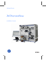
1
GE Healthcare
ÄKTAcrossflow
Installation Guide
Important user information
CE-certification
All users must read this entire manual to fully
understand the safe use of ÄKTAcrossflow.
This product complies with the European directives by
fulfilling corresponding standards.
A copy of the Declaration of Conformity is available on
request.
WARNING!
The WARNING! sign highlights instructions
that must be followed to avoid personal
injury. Do not proceed until all stated
conditions are clearly understood and
met.
The CE logo and corresponding declaration of
conformity, is valid for the instrument when it is:
–
used as a stand-alone unit, or
–
connected to other CE-marked GE Healthcare
instruments, or
CAUTION!
–
connected to other products recommended or
described in this manual, and
The CAUTION! sign highlights instructions that must be
followed to avoid damage to the product or other
equipment. Do not proceed until all stated conditions
are met and clearly understood.
–
used in the same state as it was delivered from GE
Healthcare except for alterations described in this
manual.
Notes
Note: A Note is used to indicate information that is
important for trouble-free and optimal use of the
product.
Recycling
This symbol indicates that the waste of
electrical and electronic equipment must not
be disposed as unsorted municipal waste and
must be collected separately. Please contact
an authorized representative of the
manufacturer for information concerning the
decommissioning of equipment.
WARNING!
This is a Class A product. In a domestic environment, it
might cause radio interference, in which case the user
might be required to take appropriate measures.
WARNING!
All repairs should be done by personnel authorized by
GE Healthcare. Do not open any covers or replace any
parts unless specifically stated in the instructions.
WARNING!
The computer should be installed and used according
to the instructions provided by the manufacturer of the
computer.
WARNING!
The mains power switch or other disconnect device
must always be easy to access.
Note: The Declaration of conformity is valid only for
systems that are marked with the CE logo:
Contents
1
About this installation guide
1.1
1.2
Installation .........................................................................................................7
Associated documentation .......................................................................7
2
Safety
3
Pre-requisites
4
Installation overview
5
Installation of ÄKTAcrossflow
5.1
5.1.1
5.2
5.3
5.4
5.5
5.5.1
5.5.2
5.5.3
5.5.4
5.6
5.7
Room climate.................................................................................................... 15
Unpacking the instrument ......................................................................16
Lifting the instrument ................................................................................18
Moving the instrument .............................................................................20
Installing ..........................................................................................................22
Reservoir holder............................................................................................... 23
Reservoir ............................................................................................................. 25
Bottle holders.................................................................................................... 26
Bag holder (optional) ..................................................................................... 27
Connecting the tubing ..............................................................................28
Leveling the instrument ...........................................................................30
5.7.1
Top cover ............................................................................................................ 32
5.8
5.9
5.10
5.11
Installing the computer and the mains cable ................................33
Installing the Ethernet communication cable ...............................34
CU-950 configuration ...............................................................................34
Connecting Frac-920 (optional) to ÄKTAcrossflow ......................35
5.11.1
5.11.2
6
Site environment .........................................................................................15
Connecting to mains supply....................................................................... 35
UniNet-1 communication ............................................................................ 38
Installation test
6.1
6.1.1
6.2
6.2.1
6.2.2
6.2.3
6.3
6.4
6.4.1
Preparation of ÄKTAcrossflow ..............................................................41
Starting the system ........................................................................................ 41
The installation test ....................................................................................43
Preparing the installation test ................................................................... 43
Level sensor calibration ............................................................................... 44
Run the installation test ............................................................................... 46
Description of the Installation Test .....................................................50
Evaluating the installation test results ..............................................52
How to start the evaluation procedure manually ............................ 56
7
Troubleshooting the Installation Test
8
Installation record
ÄKTAcrossflow Installation Guide 11-0012-35 Edition AD
iii
9
iv
Registration form
ÄKTAcrossflow Installation Guide 11-0012-35 Edition AD
About this installation guide 1
1
About this installation guide
WARNING! This instrument is intended for laboratory use only, not for
clinical or in vitro diagnostic purposes.
ÄKTAcrossflow™ is assembled and fully tested before shipping.
For safe transportation, however, some components have been detached and
therefore need to be remounted.
This guide describes how to install ÄKTAcrossflow. The guide is divided into two
parts; one describing the installation and one describing how to run the
installation test. After the installation procedure has been performed, your
ÄKTAcrossflow is ready for filtration work.
For full details of specifications, methods, maintenance, etc., refer to the
respective User Manuals and Instructions.
1.1
Installation
Important! The installation of ÄKTAcrossflow must be performed by
personnel authorized by GE Healthcare.
1.2
Associated documentation
The following documentation is also included with the ÄKTAcrossflow system:
The ÄKTAcrossflow Instrument Handbook contains technical information,
maintenance schedules and instructions for troubleshooting and user
maintenance.
The ÄKTAcrossflow User Manual contains detailed operating instructions.
The ÄKTAcrossflow Safety Handbook contains safety information.
The ÄKTAcrossflow Method Handbook provides more detailed information on
applications.
ÄKTAcrossflow Installation Guide 11-0012-35 Edition AD
7
1 About this installation guide
1.2 Associated documentation
The UNICORN™ control system package includes three manuals:
•
Getting Started
•
User Reference Manual (2 pcs)
•
Administration and Technical Manual
Documentation of the ÄKTAcrossflow specific Evaluation module includes:
8
•
User Reference Manual – UNICORN 5.1 – Evaluation for cross-flow
•
Specific sections in Online Help
ÄKTAcrossflow Installation Guide 11-0012-35 Edition AD
Safety 2
2
Safety
•
This system is designed for indoor use only.
•
Do not use the system in a dusty atmosphere or close to spraying water.
•
The instrument unit and the PC should be installed and prepared by
personnel authorized by GE Healthcare.
WARNING! Heavy object! The instrument unit weighs 70 kg. Use suitable
lifting equipment when moving the instrument. Wear safety shoes.
WARNING! The instrument must always be used with the protective earth
lead of the power cord correctly grounded to earth at the mains outlet.
Refer also to ÄKTAcrossflow Safety Handbook for safety information.
ÄKTAcrossflow Installation Guide 11-0012-35 Edition AD
9
2 Safety
10
ÄKTAcrossflow Installation Guide 11-0012-35 Edition AD
Pre-requisites 3
3
Pre-requisites
WARNING! ÄKTAcrossflow must be connected to a grounded mains socket.
•
For lifting instructions, see sections 5.3 and 5.4.
•
To install ÄKTAcrossflow, a working area of about 120 × 60 cm is required.
•
ÄKTAcrossflow requires 100 to 240 V~, 50 to 60 Hz electrical supply with
safety grounding.
•
A waste flask is needed.
•
The installation test requires the following solutions:
- 3 L of distilled water.
- 1000 ml 1M NaCl with 0.4% acetone and 15 mM phosphoric acid added.
ÄKTAcrossflow Installation Guide 11-0012-35 Edition AD
11
3 Pre-requisites
12
ÄKTAcrossflow Installation Guide 11-0012-35 Edition AD
Installation overview 4
4
Installation overview
•
Unpack ÄKTAcrossflow....................................................................................................... 16
•
Detach packing material................................................................................................... 16
•
Lifting the instrument ......................................................................................................... 18
•
Moving the instrument....................................................................................................... 20
•
Levelling the instrument.................................................................................................... 30
•
Unpack and install computer.......................................................................................... 33
•
Connect mains power cabling........................................................................................ 33
•
Connect ethernet communication cabling .............................................................. 34
•
Unpack and install Frac-920 (optional) ...................................................................... 35
•
Complete the first two sections of the installation record................................ 63
•
Prepare ÄKTAcrossflow for the installation test ..................................................... 41
•
Run the installation test..................................................................................................... 46
•
Complete the registration form ..................................................................................... 65
•
Complete the final section of the installation record .......................................... 63
•
Store photocopies of all records and forms in the System Logbook.
ÄKTAcrossflow Installation Guide 11-0012-35 Edition AD
13
4 Installation overview
14
ÄKTAcrossflow Installation Guide 11-0012-35 Edition AD
Installation of ÄKTAcrossflow 5
5
Installation of ÄKTAcrossflow
5.1
Site environment
5.1.1
Room climate
Bench space
The ÄKTAcrossflow instrument should be placed on a stable and level laboratory
bench. Allow space for the monitor beside the instrument.
ÄKTAcrossflow instrument dimensions
620 × 400 × 650 mm (W × D × H)
Weight, instrument unit
70 kg
Environment
Operating temperature
4 to 40°C (39 to 104°F)
Relative humidity, operation
20 to 95% (non-condensing)
Air pressure
75 to 105 kPa (up to 2000 m altitude)
The instrument must not be exposed to direct sunlight. Dust in the surrounding
atmosphere should be kept to a minimum.
Power requirements
Mains voltage
100 to 240 V~ ±10%, 50 to 60Hz (Auto range)
(Installation category II)
Power consumption
ÄKTAcrossflow Installation Guide 11-0012-35 Edition AD
900 VA
15
5 Installation of ÄKTAcrossflow
5.2 Unpacking the instrument
5.2
Unpacking the instrument
Follow the step-by-step instructions below and fill in the Installation Record as
you go along, see page 63.
Note: Some items are packed in separate boxes delivered with the system.
Note: Packing lists are included in the boxes.
16
•
After removing the cardboard hood and other packing material check the
contents against the enclosed packing list. Also check all enclosed boxes.
Store all the boxes and plastic bags in a convenient nearby place.
•
Open the plastic cover from the top and fold down to uncover the system.
Take care not to damage any tubing or components while doing this.
ÄKTAcrossflow Installation Guide 11-0012-35 Edition AD
Installation of ÄKTAcrossflow 5
•
Remove the plastic cover from the system.
•
Save all the original packing material. If the equipment has to be repacked, for transportation or otherwise, it is important that the system can
be safely packed using the original packing material.
ÄKTAcrossflow Installation Guide 11-0012-35 Edition AD
17
5 Installation of ÄKTAcrossflow
5.3 Lifting the instrument
5.3
Lifting the instrument
WARNING! Heavy object. The ÄKTAcrossflow instrument weighs 70 kg. Use
suitable lifting equipment to lift the instrument. Wear safety shoes.
WARNING! Heavy object. The ÄKTAcrossflow instrument weighs 70 kg. A
minimum of two people are required to lift the instrument. Wear safety
shoes.
After unpacking the instrument, lifting equipment is needed to lift the
instrument. If lifting equipment is not available, see instructions in section 5.4.
Note: The top cover is not mounted at delivery.
1
A lifting strap is attached to the instrument at delivery, see figure below.
Lifting strap
WARNING! The instrument has feet with low friction. To prevent the
instrument from sliding, the workbench surface must not be inclined. When
moving the instrument on a trolley, the instrument must be secured.
18
ÄKTAcrossflow Installation Guide 11-0012-35 Edition AD
Installation of ÄKTAcrossflow 5
2
Lift the instrument onto the workbench, or onto a trolley for transportation.
ÄKTAcrossflow Installation Guide 11-0012-35 Edition AD
19
5 Installation of ÄKTAcrossflow
5.4 Moving the instrument
5.4
Moving the instrument
WARNING! The instrument has a high center of gravity. Due to the risk of
tipping over, do not place the instrument close to the edge of the bench.
WARNING! The instrument has feet with low friction. To prevent the
instrument from sliding, the bench surface must not be inclined.
WARNING! Heavy object. The ÄKTAcrossflow instrument weighs 70 kg. A
minimum of two people are required to lift the instrument. Wear safety
shoes.
CAUTION! Bottle holders and the bag holder should not be mounted when
lifting and moving the instrument.
If a smaller movement of the instrument is necessary on the laboratory bench,
the instrument can be moved by carefully pushing it along the bench surface.
If a smaller lift of the instrument is necessary (i.e., without using lifting
equipment) proceed as follows:
20
ÄKTAcrossflow Installation Guide 11-0012-35 Edition AD
Installation of ÄKTAcrossflow 5
1
Use the slits in the bottom frame (two slits on each side, see figures below)
to manually lift the instrument.
Right-hand side cover
Slits
Left-hand side cover
Slits
Note: There is no need to remove the side covers when lifting the
instrument manually.
ÄKTAcrossflow Installation Guide 11-0012-35 Edition AD
21
5 Installation of ÄKTAcrossflow
5.5 Installing
5.5
Installing
Begin by creating a clean and dry working area of 120 × 60 cm that allows easy
access.
WARNING! Select a place for ÄKTAcrossflow where it is easy to access the
mains power switch on the rear panel of the instrument.
WARNING! Do not block the rear panel of the system. The mains power
switch must always be easy to access.
Then follow the step-by-step instructions below and fill in the installation record
as you go along, see page 63.
For safe transportation the following components have been detached and
thus need to be remounted:
•
Reservoir holder
•
Reservoir
•
Bottle holders
•
Bag holder (optional)
Bag holder,
rear position
(Upper rail, hidden)
Bottle holders
Bottle holders
Reservoir
Reservoir holder
Fig 5-1. Location of components to be remounted.
22
ÄKTAcrossflow Installation Guide 11-0012-35 Edition AD
Installation of ÄKTAcrossflow 5
5.5.1
Reservoir holder
Install the reservoir holder as follows:
1
Unpack the reservoir holder.
Reservoir holder
Stirrer drive motor
cable
2
Locate the reservoir holder bracket on the instrument unit.
Reservoir holder bracket
3
Attach the reservoir holder.
ÄKTAcrossflow Installation Guide 11-0012-35 Edition AD
23
5 Installation of ÄKTAcrossflow
5.5 Installing
4
Tighten the attachment screw. Locate the instrument’s stirrer drive motor
cable and connect the cables.
Attachment screw
5
Stirrer drive motor
connection
Insert the connected stirrer drive motor cable into the cable holder under
the instrument.
Cable holder
24
ÄKTAcrossflow Installation Guide 11-0012-35 Edition AD
Installation of ÄKTAcrossflow 5
5.5.2
1
Reservoir
Place the reservoir onto the reservoir holder.
Reservoir
Outlet to feed pump
manifold
Inlet (retentate return)
Reservoir level sensor
Bottom end plate
Reservoir holder
2
Connect the reservoir level sensor cable to the instrument front panel
connector.
Connection for reservoir level
sensor cable
Reservoir level sensor
Note: When using the large reservoir (1100 ml) the reservoir level sensor
cannot be installed at a right angle towards the front panel as shown
in the figure above. The reservoir must be rotated to a suitable
position for the level sensor.
ÄKTAcrossflow Installation Guide 11-0012-35 Edition AD
25
5 Installation of ÄKTAcrossflow
5.5 Installing
3
Connect the inlet and outlet tubing.
Inlet tubing
(Retentate return)
Outlet tubing to feed
pump manifold
Reservoir level sensor
5.5.3
Bottle holders
Attach the bottle holders into the rails on the instrument unit, see Fig 5-1.
The knob on the bottle holder should fit into the holes in the rail for correct
position, and the locking device (spring-loaded ball) will keep the holder in place.
Locking
device
Knob
Fig 5-2. Bottle holder.
26
ÄKTAcrossflow Installation Guide 11-0012-35 Edition AD
Installation of ÄKTAcrossflow 5
5.5.4
Bag holder (optional)
Mount the bag holder to the ÄKTAcrossflow instrument by attaching the bag
holder hooks to the upper rail on the right-hand side of the instrument, see
Fig 5-1.
Note: The bag holder can only be placed in two positions; the front or the rear
position on the upper rail, see Fig 5-1.
Hooks
Fig 5-3. Bag holder.
ÄKTAcrossflow Installation Guide 11-0012-35 Edition AD
27
5 Installation of ÄKTAcrossflow
5.6 Connecting the tubing
5.6
Connecting the tubing
The tubing connections on the instrument are not complete on delivery. All
necessary tubing is however included in the delivery and has to be connected
before operating the equipment. There are a large number of tubes and
connection points. Refer to section 5.1.7 “System flow path” in the Instrument
Handbook for detailed information.The factory tubing connections are shown in
Fig 5-4.
.
Fig 5-4. Tubes connected on delivery
Several of the tube connections are plugged when the instrument is delivered.
Tubes that may have to be connected are those from the transfer valve blocks,
the permeate valve block, the air sensor, the retentate valve block and the
reservoir.
The tubing to and from the feed pumps may also have to be reconnected
depending on the application. Generally, connections are made according to
the application. Refer to the instrument handbook, section 2.2.2 “Configuration
of tubing kits for high and low flow applications”.
28
ÄKTAcrossflow Installation Guide 11-0012-35 Edition AD
Installation of ÄKTAcrossflow 5
All the tubes are tagged to show where they should be connected. The parts to
which tubes are connected are shown in Fig 5-5.
.
Transfer pump
P-982
Permeate pump
pump P-982
Transfer pressure
sensor
pH sensor Permeate valve
block
P-PCV
Conductivity
cell
UV
cell
R-PCV
Transfer purge
valve
Feed pump
P-984
Reservoir
Retentate valve
block
Transfer valve
Air sensor
block 2
Transfer valve
block 1
Fig 5-5. Connected and ready for operation
Be sure to tighten the connectors properly to ensure that no air is sucked into
the system and that no liquid leaks out.
ÄKTAcrossflow Installation Guide 11-0012-35 Edition AD
29
5 Installation of ÄKTAcrossflow
5.7 Leveling the instrument
5.7
Leveling the instrument
After placing the ÄKTAcrossflow instrument on the laboratory bench, the
instrument must be leveled.
The instrument base frame is equipped with four feet. One foot is fixed (the rear
right-hand side) and the other three are adjustable, see figure below.
Fixed foot
Hex socket cap screw
Locking nut
Fig 5-6. Leveling the instrument.
The two feet in the front have accessible positions for adjustment, see Fig 5-6.
30
ÄKTAcrossflow Installation Guide 11-0012-35 Edition AD
Installation of ÄKTAcrossflow 5
However, to adjust the rear left-hand foot, the side cover must be removed, see
figure below.
Side cover, left-hand
Guide pins, long
Rear left-hand foot
Tip! When remounting the left-hand side cover, first attach the side cover on the
lower long guide pins, and then attach to the upper short guide pins, see figure
above.
To level the instrument (see Fig 5-6):
1
Loosen the locking nuts.
2
Using a 4 mm Allen key, adjust the height with the hex socket cap screws.
3
Check the leveling by using a spirit level on the upper plane.
4
Tighten the locking nut.
ÄKTAcrossflow Installation Guide 11-0012-35 Edition AD
31
5 Installation of ÄKTAcrossflow
5.7 Leveling the instrument
5.7.1
Top cover
Attach the top cover by first laying it down, and then sliding it backwards to the
rear position, see figure below.
Top cover
Rear position
32
ÄKTAcrossflow Installation Guide 11-0012-35 Edition AD
Installation of ÄKTAcrossflow 5
5.8
Installing the computer and the mains cable
CAUTION! The computer should be installed and used according to the
instructions provided by the manufacturer of the computer.
Unpack and set up the computer according to the manufacturer’s instructions.
Do not switch on!
ÄKTAcrossflow
Computer
Mains cables
Fig 5-7. Mains cables.
Connect one end of the supplied mains cable to the ÄKTAcrossflow mains inlet,
and the other end to a mains supply outlet with protective ground.
Connect one end of the supplied mains cable to the PC mains inlet, and the
other end to a mains supply outlet with protective ground.
ÄKTAcrossflow Installation Guide 11-0012-35 Edition AD
33
5 Installation of ÄKTAcrossflow
5.9 Installing the Ethernet communication cable
5.9
Installing the Ethernet communication cable
CAUTION! The mains power to ÄKTAcrossflow and the PC must be switched
OFF before the Ethernet cabling is installed.
ÄKTAcrossflow
Computer
Ethernet
Fig 5-8. Ethernet communication cable.
One end of the Ethernet communication cable is connected to ÄKTAcrossflow at
delivery. Connect the other end to an Ethernet communication port.
5.10
CU-950 configuration
For instructions on configuration of the CU-950, refer to ÄKTAcrossflow Service
Manual.
The mechanical and electrical installation phase of ÄKTAcrossflow is now
complete.
34
ÄKTAcrossflow Installation Guide 11-0012-35 Edition AD
Installation of ÄKTAcrossflow 5
5.11
Connecting Frac-920 (optional) to ÄKTAcrossflow
5.11.1
Connecting to mains supply
To locate the Mains connector on Frac-920, see Fig 5-9 below.
Note! Frac-920 is tilted to
allow access to the rear
panel.
Frac-920 Rear panel
Drop
Counter Valve
Monitor/
Event mark
Drop
sensor
Auxiliary
equipment
Valve
Remote
UniNet-1
Mains
Remote
digital I/O
UniNet-1
Mains
Fig 5-9. Frac-920, connectors.
Note: Frac-920 contains no user replaceable fuse.
ÄKTAcrossflow Installation Guide 11-0012-35 Edition AD
35
5 Installation of ÄKTAcrossflow
5.11 Connecting Frac-920 (optional) to ÄKTAcrossflow
To connect Frac-920 to ÄKTAcrossflow, do as follows:
1
Remove the instrument’s top cover by first sliding it towards the front panel
and then lift up.
Top cover
2
Using the two handles, remove the rear panel by first moving the handles
sidewards to the left, and then lift out the panel.
Handles
CAUTION! The free mains outlet inside the ÄKTAcrossflow instrument is
intended for connection of the fraction collector Frac-920 only.
36
ÄKTAcrossflow Installation Guide 11-0012-35 Edition AD
Installation of ÄKTAcrossflow 5
3
Connect the supplied mains cable between Frac-920 and the free mains
socket inside the ÄKTAcrossflow instrument.
Free mains outlet for connection of Frac-920
CU-950 and VAP-980
mounting plate
Frac-920 mains cable
Note: The illustration above shows the mains outlet from inside the
ÄKTAcrossflow instrument with the rear panel removed.
Note: For easy access inside the instrument, the CU-950 and VAP-980
mounting plate is suspended pivotally.
ÄKTAcrossflow Installation Guide 11-0012-35 Edition AD
37
5 Installation of ÄKTAcrossflow
5.11 Connecting Frac-920 (optional) to ÄKTAcrossflow
5.11.2
UniNet-1 communication
CAUTION! The mains power to the ÄKTAcrossflow system and the PC must
be switched off before connecting the instrument to the UniNet-1 link.
To include the fraction collector in the UniNet-1 communication chain, do as
follows:
1
Remove the right-hand side cover by first loosening the locking screw
inside the instrument one turn.
Locking screw
Note: The locking screw is intended primarily for EMC grounding.
2
38
Lift up and remove the side cover.
ÄKTAcrossflow Installation Guide 11-0012-35 Edition AD
Installation of ÄKTAcrossflow 5
3
Locate and remove the UnitNet-1 termination plug, and connect one end of
the UniNet-1 cable (included with the fraction collector) instead.
UniNet-1 termination plug
Tip! Save the termination plug in, for example, the accessory box.
4
Connect the other end of the UniNet-1 cable to Frac-920, see
Fig 5-9 and Fig 5-10.
ÄKTAcrossflow
Computer
Fraction collector
UniNet-1
Ethernet
Fig 5-10. Communication cabling including a fraction collector.
ÄKTAcrossflow Installation Guide 11-0012-35 Edition AD
39
5 Installation of ÄKTAcrossflow
5.11 Connecting Frac-920 (optional) to ÄKTAcrossflow
40
ÄKTAcrossflow Installation Guide 11-0012-35 Edition AD
Installation test 6
6
Installation test
The installation test is designed to check the function of all pumps and valves,
and the monitoring system of ÄKTAcrossflow. The installation test can be used
at any time to check the condition of the system.
IMPORTANT! The level sensor must always be calibrated before
performing the installation test.
6.1
Preparation of ÄKTAcrossflow
6.1.1
Starting the system
To start the ÄKTAcrossflow system:
1
Switch on the instrument at the mains power switch located on the rear
panel.
Mains power switch
•
The Power indicator on the front panel flashes slowly until the internal
communication with the CU (Control Unit) is established.
Power indicator
•
The Power indicator displays a constant green light when the internal
ÄKTAcrossflow Installation Guide 11-0012-35 Edition AD
41
6 Installation test
6.1 Preparation of ÄKTAcrossflow
communication with the CU is established.
2
Switch on power to the PC and the monitor.
3
Start and log on to UNICORN by double-clicking on the icon on the
Microsoft™ Windows™ desktop.
4
Enter Username and Password and click OK.
Note: When log on for the first time, enter default as user name and
password. For instructions on how to change user name and
password, refer to ÄKTAcrossflow User Manual.
5
In the System Control module, select System:Connect... to connect
UNICORN to the instrument unit.
System 1
6
42
Select the appropriate system name and click OK.
ÄKTAcrossflow Installation Guide 11-0012-35 Edition AD
Installation test 6
When the communication between UNICORN and the instrument unit is
established:
•
There is a constant green light on the Power indicator on the front
panel.
•
The green Run indicator in the status bar in UNICORN is lit.
•
The Connection box shows Yes.
6.2
The installation test
6.2.1
Preparing the installation test
Prior to running the installation test, follow the instructions below:
1
Place all inlet and outlet tubing, not including R-VB-Out1, R-VB-Out2 and PVB-Out1, into a bottle containing 3 liters of distilled water.
2
Place outlet tubing from the transfer purge valve, R-VB-Out1, R-VB-Out2
and P-VB-Out1 into a 3 L waste bottle.
Sample solution
Prepare the following sample solution for test of UV, pH and Cond:
Sample solution 1000 ml containing:
NaCl, 1.00 M
58.44 g
Acetone, 0.4%
4 ml
Phosphoric acid, 15 mM
1.0 ml H3PO4
Note: Keep the sample solution in a bottle with tight lid to avoid acetone
evaporation.
Target values for monitors:
UV
Minimum amplitude change allowed is 85.0 mAU
pH
Minimum amplitude change allowed is 2.0
ÄKTAcrossflow Installation Guide 11-0012-35 Edition AD
43
6 Installation test
6.2 The installation test
Target values for monitors:
Cond
6.2.2
Minimum amplitude change allowed is 70.0 mS/cm
Level sensor calibration
The level sensor must always be calibrated before starting the installation test.
1
In the System Control of UNICORN select File:Instant Run.
Fig 6-1. Instant run drop down menu
2
44
The window below appears. Select a system in the For system drop down
menu. In the Use frame choose the Wizard button and click Run.
ÄKTAcrossflow Installation Guide 11-0012-35 Edition AD
Installation test 6
Fig 6-2. Use Wizard button
3
In the Method Wizard dialog, select Calibrate level Sensor as method. Click
Run.
Fig 6-3. Method, Calibrate level sensor.
The level sensor will now be calibrated. The method takes about five minutes.
ÄKTAcrossflow Installation Guide 11-0012-35 Edition AD
45
6 Installation test
6.2 The installation test
6.2.3
Run the installation test
IMPORTANT!
The level sensor must always be calibrated before running the installation
test. See 6.2.2.
The reservoir must be empty before starting the installation test.
Make sure all finger tight connectors are tightened.
Note: Open the reservoir lid when performing the Installation Test! The
Installation Test will prompt you to do this.You will also be instructed
on how and where to place the waste lines.
1
In order to get a reasonable view of the Installation Test in the system
control adjust the visible curves to a minimum and open View:Properties in
the toolbar.
2
Deselect all curves and mark FeedFlow, TransferFlow, FeedPress and
ResVol.
3
Go to Y-axis and set the selected curves to Auto scale.
4
In the System Control of UNICORN select File:Instant Run.
Fig 6-4. Drop down menu
46
ÄKTAcrossflow Installation Guide 11-0012-35 Edition AD
Installation test 6
5
The window below appears. Select a system in the For system drop down
menu. In the Use frame choose the Wizard button and click Run.
Fig 6-5. Selecting the Wizard.
Read the wizard instructions carefully and follow them exactly.
6
In the Method Wizard dialog, select Installation Test as method. Click Run.
Fig 6-6. Selecting method.
ÄKTAcrossflow Installation Guide 11-0012-35 Edition AD
47
6 Installation test
6.2 The installation test
7
In the Notes window, notes on the test can be entered. Click Next.
Fig 6-7. Note pad for information on the test.
8
Method information is displayed.
Fig 6-8. Information on Method selected.
48
ÄKTAcrossflow Installation Guide 11-0012-35 Edition AD
Installation test 6
9
In the final Result Name dialog, a result name can be entered and the file
storage location can be edited.
Fig 6-9. Result name dialog.
To start the Installation test, click START.
Fig 6-10. Screen when test has started.
ÄKTAcrossflow Installation Guide 11-0012-35 Edition AD
49
6 Installation test
6.3 Description of the Installation Test
A description of the test is found in section 6.3. During the test the system will be
paused three times with a message indicating that the T-VB-In1 tubing is to be
moved as described below:
1
After 25 minutes when the first part of the test is finished. Take the T-VB-In1
tubing out of the water bottle and leave it in the air.
2
After another 10 minutes. Put the T-VB-In1 tubing in the test solution.
3
After another 5 minutes. Put the T-VB-In1 tubing back in to the water bottle.
6.3
Description of the Installation Test
First part of the test:
•
Primes all transfer valve inlets with water.
•
Checks for blockage or leakage in all eight transfer valve inlets by pumping
a specified amount of water to the reservoir.
•
During this time it also checks the transfer purge valve and the level sensor
functionality. The system will pause and give a message to end the run if
the transfer purge valve is stuck in one position.
•
The first part of the test takes 25 minutes.
Second part of the test:
50
•
Fills the reservoir with water.
•
Checks that the retentate outlet valves give the right pressure by emptying
the reservoir through these outlets
•
Tests the UV, conductivity and pH sensors by pumping the test solution
through the permeate line. This will indicate that the sensors are working
but will not show if they are calibrated correctly.
•
Checks at the same time that the Air sensor is responding by pumping air
through transfer valve inlet 1.
•
Checks that the R-PCV and P-PCV are working and that there is feed,
retentate and permeate, pressure and flow.
•
Finally it washes out the test solution with water.
•
The second part of the test will take 20 minutes.
ÄKTAcrossflow Installation Guide 11-0012-35 Edition AD
Installation test 6
Once these tests have been completed the system is filled with water and is
ready for use.
Fig 6-11. Displays the result of the first part of the installation test.
Fig 6-12. Displays the result of the second part of the installation test.
ÄKTAcrossflow Installation Guide 11-0012-35 Edition AD
51
6 Installation test
6.4 Evaluating the installation test results
6.4
Evaluating the installation test results
The system automatically prints the test result when the test is finished. The
print-out includes information about the test and indicates whether the test
results are satisfactory or not.
Below is a typical example of a test result:
TEST INFORMATION
------------------------------------------------------Installation test result
System name: Xflow_28239
UNICORN version: UNICORN 5.11 (Build 407)
Time: 2007-06-04 13:00:38 (Central European Daylight
Time)
User: John Smith
Result file: v:\UNICORN\Local\Fil\John Smith\Result
\Installation test RC5 0
------------------------------------------------------LOGBOOK EVENT TEST RESULT
---------------------------------------------Level sensor functionality, OK
------------------------------------------------------LOGBOOK EVENT TEST RESULT
---------------------------------------------Transfer purge valve: OK
------------------------------------------------------LOGBOOK EVENT TEST RESULT
---------------------------------------------T-VB-In8: OK
------------------------------------------------------LOGBOOK EVENT TEST RESULT
---------------------------------------------T-VB-In7: OK
------------------------------------------------------LOGBOOK EVENT TEST RESULT
---------------------------------------------T-VB-In6: OK
------------------------------------------------------LOGBOOK EVENT TEST RESULT
---------------------------------------------52
ÄKTAcrossflow Installation Guide 11-0012-35 Edition AD
Installation test 6
T-VB-In5: OK
------------------------------------------------------LOGBOOK EVENT TEST RESULT
---------------------------------------------T-VB-In4: OK
------------------------------------------------------LOGBOOK EVENT TEST RESULT
---------------------------------------------T-VB-In3: OK
------------------------------------------------------LOGBOOK EVENT TEST RESULT
---------------------------------------------T-VB-In2: OK
------------------------------------------------------LOGBOOK EVENT TEST RESULT
---------------------------------------------T-VB-In1: OK
------------------------------------------------------TEST INFORMATION
----------------------------------------------Installation test result
System name: Xflow_28239
UNICORN version: UNICORN 5.11 (Build 407)
Time: 2007-06-04 14:41:48 (Central European Daylight
Time)
User: John Smith
Result file: v:\UNICORN\Local\Fil\John Smith\Result
\Installation test RC5 0
------------------------------------------------------CURVE AMPLITUDE CHANGE TEST RESULT
---------------------------------------------R-VB-Out1: OK
The change in amplitude was 1.82000 bar
Minimum amplitude change allowed is 1.00000 bar
---------------------------------------------CURVE AMPLITUDE CHANGE TEST RESULT
---------------------------------------------R-VB-Out2: OK
The change in amplitude was 1.41000 bar
ÄKTAcrossflow Installation Guide 11-0012-35 Edition AD
53
6 Installation test
6.4 Evaluating the installation test results
Minimum amplitude change allowed is 1.00000 bar
------------------------------------------------------CURVE AMPLITUDE CHANGE TEST RESULT
---------------------------------------------R-VB-Out3: OK
The change in amplitude was 1.89000 bar
Minimum amplitude change allowed is 1.00000 bar
------------------------------------------------------CURVE AMPLITUDE CHANGE TEST RESULT
---------------------------------------------UV sensor: OK
The change in amplitude was 111.74500 mAU
Minimum amplitude change allowed is 85.00000 mAU
------------------------------------------------------CURVE AMPLITUDE CHANGE TEST RESULT
---------------------------------------------Cond sensor: OK
The change in amplitude was 101.54900 mS/cm
Minimum amplitude change allowed is 70.00000 mS/cm
------------------------------------------------------CURVE AMPLITUDE CHANGE TEST RESULT
---------------------------------------------pH sensor: OK
The change in amplitude was 3.91000
Minimum amplitude change allowed is 2.00000
------------------------------------------------------Logbook Event test result
---------------------------------------------Air sensor OK
------------------------------------------------------CURVE AMPLITUDE CHANGE TEST RESULT
---------------------------------------------R-PCV/P-PCV, OK
The change in amplitude was 0.66000 bar
Minimum amplitude change allowed is 0.17000 bar
------------------------------------------------------CURVE AMPLITUDE CHANGE TEST RESULT
---------------------------------------------Feed pressure sensor,
OK
54
ÄKTAcrossflow Installation Guide 11-0012-35 Edition AD
Installation test 6
The change in amplitude was 1.89000 bar
Minimum amplitude change allowed is 0.20000 bar
------------------------------------------------------CURVE AMPLITUDE CHANGE TEST RESULT
---------------------------------------------Retentate pressure sensor,
OK
The change in amplitude was 1.59000 bar
Minimum amplitude change allowed is 0.20000 bar
------------------------------------------------------CURVE AMPLITUDE CHANGE TEST RESULT
---------------------------------------------Permeate pressure sensor,
OK
The change in amplitude was 1.68000 bar
Minimum amplitude change allowed is 0.20000 bar
------------------------------------------------------CURVE AMPLITUDE CHANGE TEST RESULT
---------------------------------------------Feed flow detected,
OK
The change in amplitude was 350.00000 ml/min
Minimum amplitude change allowed is 1.00000 ml/min
------------------------------------------------------CURVE AMPLITUDE CHANGE TEST RESULT
---------------------------------------------Permeate flow detected,
OK
The change in amplitude was 200.00000 ml/min
Minimum amplitude change allowed is 1.00000 ml/min
------------------------------------------------------CURVE AMPLITUDE CHANGE TEST RESULT
---------------------------------------------Transfer flow detected,
OK
The change in amplitude was 200.00000 ml/min
Minimum amplitude change allowed is 1.00000 ml/min
------------------------------------------------------Note:
If the system is equipped with an old type of retentate valve block,
the test result of R-VB-Out1-3 will be “Failed”.
The installation test is now complete and the unit can be used in normal
operation.
ÄKTAcrossflow Installation Guide 11-0012-35 Edition AD
55
6 Installation test
6.4 Evaluating the installation test results
If any parts of the test should fail refer to the troubleshooting table in this
document or consult the instrument handbook for more detailed
troubleshooting guidelines.
A failure may sometimes be caused by something as basic as a leaking
connection that has not been tightened properly. Always check the basics
before heading into advanced fault analysis.
6.4.1
How to start the evaluation procedure manually
If for some reason no printout was generated even though the evaluation was
performed correctly then proceed as follows.
•
Open the result file in the UNICORN Evaluation window and click on the
first chromatogram to make it active.
Fig 6-13. Evaluation.
56
ÄKTAcrossflow Installation Guide 11-0012-35 Edition AD
Installation test 6
•
Select Procedures: Edit: New.
Fig 6-14. Select new procedure.
In the Procedure Edit window Select File: Open from file:
Trf_ValveBlockTest_AD.
.
Fig 6-15. Procedure editor.
ÄKTAcrossflow Installation Guide 11-0012-35 Edition AD
57
6 Installation test
6.4 Evaluating the installation test results
•
Select Control: Run and the first part of the report will be printed.
Fig 6-16. Run procedure.
At this point, close the Procedure Edit window to return to the evaluation
diagrams. Click on the second chromatogram to make this window active.
.
Fig 6-17. Evaluation 2.
58
ÄKTAcrossflow Installation Guide 11-0012-35 Edition AD
Installation test 6
In the drop down menu select Procedures: Edit: New.
In the Procedure editor choose File: Open from file: Mon_Valve_TestAD.
Fig 6-18. Selection of Mon_Valve_TestAD.
Select Control: Run and the second part of the report will be printed.
ÄKTAcrossflow Installation Guide 11-0012-35 Edition AD
59
6 Installation test
6.4 Evaluating the installation test results
60
ÄKTAcrossflow Installation Guide 11-0012-35 Edition AD
Troubleshooting the Installation Test 7
7
Troubleshooting the Installation Test
The table below describes some of the faults that may arise when performing
the installation test.
Failed Unit
Possible cause
T-VB-in 1 to 8
Mismatch between in and out
volumes.
R-VB-Out 1 to 3
Corrective action
Air is drawn in.
Check all fingertights.
Inlet tubing is not immersed in
the water.
Make sure that the inlet tube is immersed in
water.
Reservoir was not empty from
the start.
Repeat the test with the reservoir empty from
the beginning.
Obstruction in the flow path.
Check all flow paths and replace if necessary.
Transfer valve blocked.
Disassemble the connection block and clean
it.
The transfer purge valve is
leaking.
Contact your GEHC Service representative for
replacement of the valve.
The level sensor is broken.
Replace the level sensor. Make sure the
system is in End mode before starting the
system.
The retentate valve outlet does
not provide enough counter
pressure.
Old valve block is used.
No action is required since the old valve block
will not provide any back pressure.
Retentate valve incorrectly
calibrated.
The retentate valve is incorrectly calibrated.
Contact your GEHC Service representative.
Cond sensor
The Cond value did reach its
limit
Check calibration/ Check test solution
UV sensor
The UV did not reach its limit.
Check filter settings / Check test solution
Wrong UV filter installed.
Make sure the 280 mm filter is installed and
the position of the lamp housing is correct.
ÄKTAcrossflow Installation Guide 11-0012-35 Edition AD
61
7 Troubleshooting the Installation Test
Failed Unit
Possible cause
Corrective action
pH sensor
The pH value did not reach its
limit.
Check calibration/ Check test solution
Sensor not calibrated
Calibrate the sensor
Sensor broken.
Replace the sensor.
R-PCV / P-PCV
The R-PCV or the P-PCV valve
did not provide enough counter
pressure.
Contact your GEHC Service representative.
Pressure sensors
The sensor did not detect any
pressure
Check for leakage
Pressure sensor broken
Contact your GEHC Service representative for
replacement of broken parts
R-PCV or P-PCV broken
Contact your GEHC Service representative for
replacement of broken parts
Pump flow detection
The pump did not report any
flow.
Contact your GEHC Service representative.
Air sensor
Air sensor broken.
Contact your GEHC Service representative.
Permeate outlets
High pressure alarm.
Disassemble and clean the permeate valve
outlets. If this does not work, call service.
62
ÄKTAcrossflow Installation Guide 11-0012-35 Edition AD
Installation record 8
8
Installation record
Check
Sign
Remarks
1 Unpacking
•
Contents according to packing lists.
•
No visible damage.
2 Installation
•
Reservoir holder and reservoir installed.
•
Transfer purge valve (Waste 1) extended to waste reservoir.
•
Computer and computer display installed.
•
Ethernet cabling installed.
•
Frac-920 unpacked and installed.
•
UniNet-1 cabling installed.
•
Mains power cabling installed.
3 Installation test
•
Solutions prepared.
•
Tubing to piston seal rinsing system in bottles with 10 mM NaOH in
20% ethanol.
•
ÄKTAcrossflow prepared.
•
Installation Test run.
•
Registration Form completed.
•
Copy of Registration form stored in System Logbook.
•
Registration form posted to Service Administration.
•
Installation Guide stored in User Manual box for future use.
ÄKTAcrossflow Installation Guide 11-0012-35 Edition AD
63
8 Installation record
64
ÄKTAcrossflow Installation Guide 11-0012-35 Edition AD
Registration form 9
"
9
Registration form
Important!
Warranty registration information
Please ensure that this form is completed and returned to Service Administration
to register the users' equipment under warranty.
Name: ...............................................................................................................................
Institute/company: ..........................................................................................................
Address: ...........................................................................................................................
Department/location: ......................................................................................................
Post Code: ........................................................................................................................
Phone Number: ............................................... Fax Number: ........................................
End Users: ....................................................... E-mail: ...................................................
Date of Installation: .......................................... Quote No: ...........................................
Customer Order No: ......................................... Invoice No: ........................................
Support Agreement purchased with the instrument:
Y/N
If YES give details: ...............................................................................
Installer (name): ...................................................................................
Signature of Installer:...........................................................................
Installation Accepted:......................................Date:............................
Note: Fill in serial numbers over-leaf.
ÄKTAcrossflow Installation Guide 11-0012-35 Edition AD
65
9 Registration form
66
ÄKTAcrossflow Installation Guide 11-0012-35 Edition AD
For contact information for your local office,
please visit www.gelifesciences.com/contact
GE Healthcare Bio-Sciences AB
Björkgatan 30
751 84 Uppsala
Sweden
www.gelifesciences.com
GE, imagination at work and GE monogram are trademarks of General
Electric Company.
Drop Design, UNICORN, ÄKTAcrossflow and ÄKTA are trademarks of GE
Healthcare companies.
UNICORN. Any use of this software is subject to GE Healthcare Standard
Software End-User License Agreement for Life Sciences Software Products.
A copy of this Standard Software End-User License Agreement is available
on request.
All third party trademarks are the property of their respective owners.
© 2005-2007 General Electric Company – All rights reserved.
First published February, 2005
All goods and services are sold subject to the terms and conditions of sale
of the company within GE Healthcare which supplies them. A copy of these
terms and conditions is available on request. Contact your local GE
Healthcare representative for the most current information.
GE Healthcare UK Ltd
Amersham Place,
Little Chalfont,
Buckinghamshire, HP7 9NA,
UK
GE Healthcare Bio-Sciences Corp
800 Centennial Avenue,
P.O. Box 1327, Piscataway,
NJ 08855-1327,
USA
GE Healthcare Europe GmbH
Munzinger Strasse 5,
D-79111 Freiburg,
Germany
GE Healthcare Bio-Sciences KK
Sanken Bldg. 3-25-1,
Hyakunincho, Shinjuku-ku,
Tokyo 169-0073,
Japan
imagination at work
11-0012-35 AD 09/2007