1
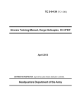
ELECTRICAL AND COMPUTER ENGINEERING DEPARTMENT, OAKLAND UNIVERSITY ECE-470/570: Microprocessor-Based System Design Fall 2014 Notes - Unit 8 PARALLEL I/O I/O devices are also called peripheral devices as they are outside the CPU. The CPU needs to specify the I/O device if it needs to perform an I/O operation. This is done by: i) specifying the address space the I/O device occupies, and ii) making use of the particular instructions and addressing modes the I/O device uses. HCS12: Memory devices (e.g.: SRAM, EEPROM) and I/O devices occupy the same address space. I/O SYNCHRONIZATION Microprocessor usually communicate with I/O devices via interface chips (or interface logic for the microcontroller). Proper communication must be carried out between: i) processor and interface logic, and ii) interface logic and the I/O devices. Parallel Ports: Data written into the data register appears on the output pins directly. Data read from the data register reflects the instantaneous voltage levels on the input pins. This capability is provided by most microcontrollers (including the HCS12). Serial Interfaces: Synchronization is achieved by following data transfer protocols. The processor needs to make sure that new data is present in the interface logic (usually held in the data register) before reading it. It also needs to make sure that the interface logic can handle more data before sending new data to the interface logic. Here, the polling and interrupt methods are very useful. HCS12 PARALLEL PORTS The Device User Guide shows the detailed register map (Section 1.6) of the MC9S12DG256 from $0000 to $03FF (1KB). The entire memory map of the device is shown in Figure 1.2. The mc9s12dg256.inc file contains all the numeric equivalent of the port numbers (and memory positions too). We will use the device in Normal Single-Chip Mode (i.e., no external buses) The user configures an I/O port for input or output by programming the associated data direction register. To output, the user writes data on the port data register. To input, the user reads data form the port data register. Most I/O ports have additional registers to control their operations, and most I/O pins service multiple purposes (some are presented here). PORT A General Purpose I/O (GPIO) Port. Data Register (PORTA): $0000. Data Direction Register (DDRA): $0002. ‘1’ means output, ‘0’ means input Dragon12-Light Board: External I/O pins. Also, they are connected to the keypad PORT B General Purpose I/O (GPIO) Port. Data Register (PORTB): $0001. Data Direction Register (DDRB): $0003. ‘1’ means output, ‘0’ means input Dragon12-Light Board: External I/O pins. Also, they are connected to the LEDs and the anodes of the 7-segment displays. PB0-PB3 are also connected to the DC Motor Driver (TB6612F NG). PORT E General Purpose I/O (GPIO) Port. Data Register (PORTE): $0008. Pin 0 is connected to /XIRQ. Pin 1 is connected to /IRQ. Data Direction Register (DDRE): $0009. ‘1’ means output, ‘0’ means input Port E Assignment Register (PEAR): $000A. Write $10 to configure all 8 bits as I/O pins. Dragon12-Light Board: External I/O pins. PORT K General Purpose I/O (GPIO) Port. Data Register (PTK): $0032. Data Direction Register (DDRK): $0033. ‘1’ means output, ‘0’ means input Dragon12-Light Board: External I/O pins. Also, PK5-PK0 they are connected to the alphanumeric LCD module (EL-1602A, controller compatible with HD44780). The LCD module operates in a write-only, 4-bits mode. PORT T General Purpose I/O (GPIO) Port. Data Register (PTT): $0240. Data Direction Register (DDRT): $0242. ‘1’ means output, ‘0’ means input PORT T pins can also be used as input capture or input capture pins on the HCS12 Timer Module. Dragon12-Light Board: External I/O pins. The speaker is driven by PT5. 1 Instructor: Daniel Llamocca ELECTRICAL AND COMPUTER ENGINEERING DEPARTMENT, OAKLAND UNIVERSITY ECE-470/570: Microprocessor-Based System Design Fall 2014 PORT S General Purpose I/O (GPIO) Port. Data Register (PTS): $0248. Data Direction Register (DDRT): $024A. ‘1’ means output, ‘0’ means input Dragon12-Light Board: External I/O pins. Also, PS0 is RXD0 (SCI0 Receive), PS1 is TXD0 (SCI0 Transmit), PS2 is RXD1 (SCI1 Receive), PS3 is TXD1 (SCI1 Transmit), PS4 is MISO0 (SPI0 input), PS5 is MOSI0 (SPI0 output), PS6 is SCK0 (SPI0 clock output), and PS7 is /SS0 (SPI0 output enable). Note that the DAC (LTC1661) uses SPI to communicate and utilizes the pins PS5 (MOSI0) and PS6 (SCK0). PORT M General Purpose I/O (GPIO) Port. Data Register (PTM): $0250. Data Direction Register (DDRM): $0252. ‘1’ means output, ‘0’ means input Module Routing Register (MODRR): $0257. This register configures the rerouting of CAN and SPI ports on defined port pins. Dragon12-Light Board: External I/O pins. Also, PM0 is CAN0 Receive, PM1 is CAN0 Transmit. The CAN chip is the MCP2551. Also, PM2 is the common anode (in negative logic) of the RGB LED, PM6 is the Chip Select (CS) input of the DAC (LTC1661). PORT H General Purpose I/O (GPIO) Port. Data Register (PTH): $0260. Data Direction Register (DDRH): $0262. ‘1’ means output, ‘0’ means input Dragon12-Light Board: External I/O pins. Also, they are connected to the DIP switch and Push Buttons (4 LSBs). PORT J General Purpose I/O (GPIO) Port. Data Register (PTJ): $0268. Data Direction Register (DDRH): $026A. ‘1’ means output, ‘0’ means input Dragon12-Light Board: External I/O pins. Also, PJ6 is the SDA pin (I2C), PJ7 is the SCL pin (I2C). PORT P General Purpose I/O (GPIO) Port. Data Register (PTP): $0258. Data Direction Register (DDRP): $025A. ‘1’ means output, ‘0’ means input If PWM is enabled, all PORT P pins can become PWM channels. Dragon12-Light Board: External I/O pins. Also, PP0-PP3 are the cathodes of the 7-segment displays. PP0-PP1 are connected to the DC Motor Driver (TB6612F NG). Also PP4-PP6 are the anodes (in negative logic) of the RGB LED. With a jumper, PP5 connects to the buzzer. PORTS AD0 AND AD1 These ports are analog input interfaces to the ADC subsystem. Each ADC has 8 channels. ATD0 Data Register (PORTAD0): $008F. ATD0 Digital Input Enable Register (ATD0DIEN): $008D. We can configure each input channel as analog input (0) or as digital input (1). ATD1 Data Register (PORTAD1): $012F. ATD1 Digital Input Enable Register (ATD1DIEN): $012D. We can configure each input channel as analog input (0) or as digital input (1). Dragon12-Light Board: External input pins. Also, some pins are connected to the light sensor, temperature sensor, Trimmer Pot (see Board User Manual). PAD0-PAD7: ATD0, PAD8-PAD15: ATD1? ELECTRICAL CHARACTERISTICS CONSIDERATIONS FOR I/O INTERFACING In addition to the microcontroller, most embedded systems use peripherals (or I/O devices). These peripherals usually feature an integrated circuit (IC). Because these ICs might use different technologies, we must make sure that they are electrically compatible: Voltage-level compatibility: The high output level of the IC must match that of another IC (which can be the microcontroller itself). Same for the low output level. Current drive capability: The output of an IC might not have enough current to drive its load. Moreover, the total current required to drive I/O devices might exceed the maximum current rating for the microcontroller. This problem is usually solved by adding buffer chips (powered externally, e.g.: 74ABT244) that can supply enough current between the microcontroller and the peripheral ICs. Another issue is Timing compatibility. An I/O pin configured as an input usually has a register that reads from a peripheral pin. An I/O pin configured as an output usually has a register whose value is read by the peripheral pin (possibly on a register). We must make sure not to violate the setup and hold time requirements on the flip flops. 2 Instructor: Daniel Llamocca ELECTRICAL AND COMPUTER ENGINEERING DEPARTMENT, OAKLAND UNIVERSITY ECE-470/570: Microprocessor-Based System Design Fall 2014 USING THE LIQUID CRYSTAL DISPLAY (LCD) The Dragon12-Light Board includes and LCD module. An LCD Module includes the LCD and its controller. The controller is compatible with the HD44780, which is the one of the most popular display controllers in use today. Features of the LCD in the Dragon12Light Board: 2 lines, 16 characters per line, only writes allowed, 4-bits mode. Interface Port: PORT K. HCS12 MCU HD44780 CONTROLLER PK0 RS PK1 EN 0 PK5..PK2 7 PTK ($0032): PTK7 6 PTK6 LCD pins: R/W DB7..DB4 5 4 3 2 1 0 PTK5 PTK4 PTK3 PKT2 PTK1 PTK0 DB7 DB6 DB5 DB4 EN RS We can access two registers in the LCD: Data Register (by setting RS=1), and Instruction Register (by setting RS = 0). When writing to either register, the enable bit must be asserted (EN=1). We can write an 8-bit value on both registers: DB7-DB0. Due to the LCD connection in the Dragon12-Light Board, we use the 4-bits mode. In a 4-bits mode, the 8-bit value is transmitted by first sending the higher nibble (DB7-DB4) and then sending the lower nibble (DB3-DB0). Both nibbles are sent using the pins DB7-DB4. PROCEDURE 1. Configure the LCD by writing a set of instructions on the Instruction Register (IR). Here, we must make RS = 0 (to select the IR). For a list of instructions, see Table 7.5 in textbook. The following is a suggested list of instructions to configure the LCD: Write 0x28: Set 4-bit data, 2-line display, 5x8 font Write 0x0F: Turn on display and cursor. Blink cursor position Write 0x06: Set cursor move direction to the right. No display shift. Write 0x80: Set DDRAM address to 0. DDRAM data are accepted on DR after this setting. Write 0x01: Clear display, return cursor to the home position (address 0, located in line 1). In addition, to move the cursor to the second line, we do: Write 0xC0: Set 4-bit data, 2-line display, 5x8 font 2. Write ASCII characters on the LCD by writing on the Data Register (DR): Here, we must make RS = 1 (to select the IR). We write on DDRAM or CGRAM (usually starting from address 0). To write on DDRAM, we first write the instruction “Set DDRAM address” on IR. To write on CGRAM, we first write the instruction “Set CGRAM address” on IR. For a 2x16 display size, the character positions and display addresses are provided in Table 7.7b in textbook. The HC44780 uses a counter to keep track of the address of the next location to be accessed. When the “Set DDRAM address” or the “Set CGRAM address” instructions are written on IR, the starting address is transferred to this counter. Then, every write to either memory will increment (cursor moves to the right) or decrement (cursor moves to the left) automatically. Whether to increment or decrement depends on the Instruction “Entry Mode Set”. WRITING A BYTE ON INSTRUCTION REGISTER OR DATA REGISTER Here, we must comply with the timing diagram in Figure 7.30 in the textbook: Writing on IR. RS = 0 - Set RS = 0, E = 0; wait 60 ns - Set E=1 - Send higher nibble; wait 80 ns - Set RS = 0, E = 0; wait 60 ns - Set E=1 - Send lower nibble; wait 80 ns - Make RS = 0, E = 0 - Wait 50 us (wait time for order to be completed, true for most instructions) Writing on DR. RS = 1 - Set RS = 1, E = 0; wait 60 ns - Set E=1 - Send higher nibble; wait 80 ns - Set RS = 1, E = 0; wait 60 ns - Set E=1 - Send lower nibble; wait 80 ns - Make RS = 1, E = 0 - Wait 50 us (wait time for order to be completed, true for most instructions) Example: Mixed C/Assembly Programming. C Code: unit8a.c mixasm.h ASM Code: mixasm.asm openLCD(): This function configures the LCD putcLCD(char cx): This function places a byte on Data Register. ASCII characters are accepted. putsLCD(char *ptr): This function places a character string on the LCD. 3 Instructor: Daniel Llamocca