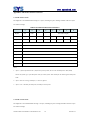
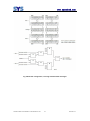
1
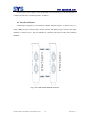
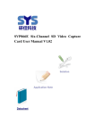
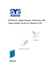
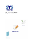
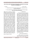
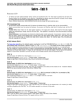
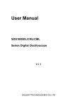
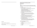
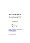
CANPCI-904 CAN Interface User Manual V1.02 www.sysembed.com Document Title: CANPCI-904 CAN Interface User Manual V1.02 Version: 1.02 Date: 2011-03-04 Status: Release Document Control ID: CANPCI-904 CAN Interface User Manual V1.02 General Notes SYSTECH offers this information as a service to its customers, to support application and engineering efforts that use the products designed by SYSTECH. The information provided is based upon requirements specifically provided to SYSTECH by the customers. SYSTECH has not undertaken any independent search for additional relevant information, including any information that may be in the customer’s possession. Furthermore, system validation of this product designed by SYSTECH within a larger electronic system remains the responsibility of the customer or the customer’s system integrator. All specifications supplied herein are subject to change. Copyright This document contains proprietary technical information which is the property of Systech copying of this document and giving it to others and the using or communication of the contents thereof, are forbidden without express authority. Offenders are liable to the payment of damages. All rights reserved in the event of grant of a patent or the registration of a utility model or design. All specification supplied herein are subject to change without notice at any time. Copyright © Systech 2012 CANPCI-904 CAN Interface User Manual V1.02 2 2012-09-12 www.sysembed.com Version History Version Data Add/Del/Rev V1.00 2011-03-04 New version V1.01 2011-04-23 According to the SYSTECH manual template format V1.02 2012-09-12 Increased Win7 operating system description CANPCI-904 CAN Interface User Manual V1.02 3 2012-09-12 www.sysembed.com Contents 1. Introduction ........................................................................................................... 7 1.1 1.2 Description ........................................................................................................................ 7 Features ............................................................................................................................. 7 2. Technical Support .................................................................................................. 8 3. About Function ...................................................................................................... 8 3.1 Summary .............................................................................................................................. 8 3.2 Parameters ............................................................................................................................ 8 3.3 Appearance........................................................................................................................... 9 4. The hardware installation and wiring ................................................................. 9 4.1 The hardware installation ..................................................................................................... 9 4.2 Interface definition ............................................................................................................ 10 4.3 Termination resistor ........................................................................................................... 11 4.3 Signal indicator LED.......................................................................................................... 12 Appendix ..................................................................................................................... 13 A: Related Documents ............................................................................................................. 13 Appendix1: The Frame Format of CAN2.0 ................................................................. 14 Appendix 2: SJA1000 Standard Baud Rate ................................................................. 16 Appendix 3: Configuration for CAN Message Filter ................................................... 17 Appendix 4: CAN-bus Communication distance(Reference Value) ...................... 22 B. Terms and Abbreviations .................................................................................................... 23 C. Safety Caution ..................................................................................................................... 24 Contact us: .................................................................................................................. 25 CANPCI-904 CAN Interface User Manual V1.02 4 2012-09-12 www.sysembed.com Table Index Table 1 The LED corresponding to the order .......................................................................... 12 Table 2 The CAN standard frame information ........................................................................ 14 Table 3 The CAN extended frame information ....................................................................... 15 Table 4 standard of baud rate setting ....................................................................................... 16 Table 5 Communication distance ............................................................................................ 22 CANPCI-904 CAN Interface User Manual V1.02 5 2012-09-12 www.sysembed.com Figure Index Fig. 1 Appearance ................................................................................................................... 9 Fig. 2 The CAN channel defined sequence ............................................................................. 10 Fig. 3 The CAN interface terminal definition ......................................................................... 11 Fig. 4 bus topology.................................................................................................................. 11 Fig. 5 Single filter configuration, receiving standard frame messages ......................... 18 Fig. 6 Single filter configuration, receiving extended frame messages ........................ 18 Fig. 7 Dual filter configuration, receiving standard frame messages ...................................... 20 Fig. 8 Dual filter configuration, receiving extended frame messages ........................... 21 CANPCI-904 CAN Interface User Manual V1.02 6 2012-09-12 www.sysembed.com 1. Introduction 1.1 Description CANPCI-904 CAN-bus interface card is the SYSTECH developed an industrial-grade computer PCI bus to CAN bus data transfer card, which uses A + B card design in the form of A card-based card, B card attached card, integrated 4-way CAN-bus interface. CANPCI-904 interface card supports 32-bit 33MHz PCI data bus compatible with the PCI 2.2 specification, Universal PCI connector, users can easily use it to complete the interconnection between the CAN-bus network and PC, you can easily, high-speed the collection of data of the CAN-bus. CANPCI-904 for industrial-grade products can work in -20 ° C to +70 ° C temperature range. CAN port communication baud rate can be arbitrarily set in the 5k ~ 1Mbps. In order to ensure good EMC and EMI performance, CANPCI-904 using completely independent CAN-bus channel, effectively prevent the PC suffered the impact of the local circulation. , 4-channel CAN interface are integrated CAN-bus common mode filter and TVS bus protection circuit, to provide security to operate in the electromagnetic environment is more complex industrial applications. CANPCI-904 interface card provides a simple API and multi-language version of the application routine, and debugging software, user-friendly control, the test CAN-bus on the bus to transfer data. 1.2 Features PC interface: 32bit 33M PCI data bus, conform to the PCI2.2 standard, plug and play; Controller:NXP SJA1000; Transceiver:Microchip MCP2551; Protocol:CAN 2.0B specification (compatible with CAN 2.0A ); Communication baud rate:5K~1Mbps; Communication interface:DB9 pin type socket, conform to the DeviceNet and CANopen standard; Isolation voltage:Magnetic isolation DC 2500V; Operating temperature:-20℃~+70℃; CANPCI-904 CAN Interface User Manual V1.02 7 2012-09-12 www.sysembed.com Storage Temperature:-40℃~+85℃; Physical size:CANPCI-904-A,Short standard PCI card 130mm×90mm; CANPCI-904-B,25 mm×90mm. 2. Technical Support If you want get technical support or the latest information about this product, please access the website: http:/www.sysembed.com. 3. About Function 3.1 Summary CANPCI-904 intelligent CAN interface module made in SYSTECH. It is convenient to Using it for collecting data, and analysing data, and processing data in building CAN-bus laboratory, or industrial control, or intelligent community, or automotive electronics. CANPCI-904 has these characteristics, such as compact design and beautiful appearance and plug-and-play etc, and it is dependable assistant in matching equipment and debugging equipment and developing equipment. 3.2 Parameters PC interface: 32bit 33M PCI data bus, conform to the PCI2.2 standard, plug and play; Controller:NXP SJA1000; Transceiver:Microchip MCP2551; Protocol:CAN 2.0B specification (compatible with CAN 2.0A ); Communication baud rate:5K~1Mbps; Communication interface:DB9 pin type socket, conform to the DeviceNet and CANopen standard; Supporting Operating System:Windows98/Me/2000/XP/2003/Win7;Linux 2.4、Linux 2.6. Adopts electrical isolation, the isolation voltage is : 2500Vrms; Max data flow for a single channel: 3000 fps (standard frame); Supports SysCanTool software. CANPCI-904 CAN Interface User Manual V1.02 8 2012-09-12 www.sysembed.com 3.3 Appearance Fig. 1 Appearance 4. The hardware installation and wiring 4.1 The hardware installation In order to ensure CANPCI-904 interface card to normal use, installation and removal, make sure the computer is off and the power-down state. CANPCI-904 interface card is an electrostatic-sensitive board, please note that in the installation and removal of electrostatic protection, wear an antistatic gloves or hand-held card edge, avoid direct contact with components. Specific installation steps are as follows: 1)Power off the PC; 2)Open the lid of the PC; 3)Insert CANPCI-904 interface card into a free slot; 4)Tightening the fixed card of bolt; 5)With the equipment included 6p ribbon cable will be the A card P2 socket and B card P2 socket connection; CANPCI-904 CAN Interface User Manual V1.02 9 2012-09-12 www.sysembed.com 6)Open the PC power supply, At this point BIOS will automatically give the the allocation of CANPCI-904 interface card interrupt and I / O address. 4.2 Interface definition CANPCI-904 integrated 4 CAN channels (channel defined sequence is shown in Fig. 2), connect DB9 pin-type connectors and CAN-bus network. The DB9 pin type connector pin signal definition is shown in Fig.3. The pin definition is consistent with the DeviceNet and CANopen standard. Fig. 2 The CAN channel defined sequence CANPCI-904 CAN Interface User Manual V1.02 10 2012-09-12 www.sysembed.com pin Signal describe No connection 1 2 CAN_L CAN_L 3 CAN_GND reference ground 4 The signal line No connection 5 CAN_SHIELD shield wires 6 CAN_GND reference ground 7 CAN_H CAN_H The signal line 8 No connection 9 No connection Fig. 3 The CAN interface terminal definition 4.3 Termination resistor Such as the CAN network using the straight-line topology, the two terminals of the bus need to install a 120-ohm terminating resistor. If the number of nodes is greater than 2, the intermediate nodes do not need to install a 120-ohm terminating resistor in Fig.4. Fig. 4 bus topology CANPCI-904 interface card for each CAN channels are integrated on-board 120-ohm terminating resistor can be set by jumper JP1 to JP4 the corresponding CAN channels using the resistance. CANPCI-904 interface card corresponding CAN channel is located in a CAN network endpoint, set the corresponding the channel jumper short circuit. Factory, 4-channel in a short-circuit condition, using an integrated 120-ohm terminating resistor. CANPCI-904 CAN Interface User Manual V1.02 11 2012-09-12 www.sysembed.com 4.3 Signal indicator LED CANPCI-904-A card onboard D2 to D5 four LEDs, which indicate the status of data transmission and reception of the four CAN channels, when the CAN channel data transceiver, the corresponding channel indicator will flash data transceiver frequency,corresponding to the sequence as shown in table 2-4. No LED CAN channel 1 D5 CAN3 2 D4 CAN2 3 D3 CAN1 4 D2 CAN0 Table 1 The LED corresponding to the order CANPCI-904-B card board integration the D1 indicator, indicating that the power connection status of the B card the D1 indicator light is, when the power is turned on. CANPCI-904 CAN Interface User Manual V1.02 12 2012-09-12 www.sysembed.com Appendix A: Related Documents SN Document name Remark 1 The Frame Format of CAN2.0 The length for CAN standard frame message is 11 bytes; The length for CAN extended frame message is 13 bytes. 2 SJA1000 Standard Baud Rate standard of baud rate setting 3 Configuration for CAN Message Filter The CAN message filter of the converter is designed based on the PeliCAN mode of the CAN controller SJA1000 (made by PHILIPS). 4 CAN-bus distance CAN-bus Communication distance corresponding to the table Communication CANPCI-904 CAN Interface User Manual V1.02 13 2012-09-12 www.sysembed.com Appendix1: The Frame Format of CAN2.0 CAN2.0B standard frame: The length for CAN standard frame message is 11 bytes, including two parts: message and data. The first 3 bytes are used for message. Table 2 The CAN standard frame information 7 6 5 4 3 2 1 0 Byte 1 FF RTR × × Byte 2 ID.10 ID.9 ID.8 ID.7 ID.6 ID.5 ID.4 ID.3 Byte 3 ID.2 ID.1 ID.0 × × × × × DLC(Data Length) Byte 4 Data1 Byte 5 Data 2 Byte 6 Data 3 Byte 7 Data 4 Byte 8 Data 5 Byte 9 Data 6 Byte 10 Data 7 Byte 11 Data 8 Notes: 1. Byte 1 is frame information. Bit 7 (FF) denotes frame format, FF=0 in the standard frame. Bit 6 (RTR) denotes the frame type, 0 for data frame and 1 for remote frame. DLC stands for the data length in data frame mode. 2. Byte 2 and 3 are message identifiers, 11 bits are effective. 3. Byte 4 to 11 is the data for data frame, invalid for remote frame. CAN2.0B extended frame The length for CAN extended frame message is 13 bytes, including two parts: message and data. The first 5 bytes are used for message. CANPCI-904 CAN Interface User Manual V1.02 14 2012-09-12 www.sysembed.com Table 3 The CAN extended frame information 7 6 5 4 3 2 1 0 Byte 1 FF RTR × × Byte 2 ID.28 ID.27 ID.26 ID.25 ID.24 ID.23 ID.22 ID.21 Byte 3 ID.20 ID.19 ID.18 ID.17 ID.16 ID.15 ID.14 ID.13 Byte 4 ID.12 ID.11 ID.10 ID.9 ID.8 ID.7 ID.6 ID.5 Byte 5 ID.4 ID.3 ID.2 ID.1 ID.0 × × × DLC(Data Length) Byte 6 Data 1 Byte 7 Data 2 Byte 8 Data 3 Byte 9 Data 4 Byte 10 Data 5 Byte 11 Data 6 Byte 12 Data 7 Byte 13 Data 8 Notes: 1. Byte 1 is frame information. Bite 7 (FF) denotes the frame format, FF=1 for extended frame. Bite 6 (RTR) denotes the frame type, 0 for data frame and 1 for remote frame. DLC stands for the data length in the data frame. 2. Byte 2 and 5 are message identifiers, the higher 29 bits are effective. 3. Byte 6 to 13 is the data for data frame, invalid for remote frame. CANPCI-904 CAN Interface User Manual V1.02 15 2012-09-12 www.sysembed.com Appendix 2: SJA1000 Standard Baud Rate Table 4 standard of baud rate setting Baud Rate(Kbps) BTR0(Hex) BTR1(Hex) 1 5 BF FF 2 10* 31 1C 3 20* 18 1C 4 40 87 FF 5 50* 09 1C 6 80 83 FF 7 100* 04 1C 8 125* 03 1C 9 200 81 FA 10 250* 01 1C 11 400 80 FA 12 500* 00 1C 13 666 80 B6 14 800* 00 16 15 1000* 00 14 Note: Those with “*” are the Baud rates that recommended by CIA union. CANPCI-904 CAN Interface User Manual V1.02 16 2012-09-12 www.sysembed.com Appendix 3: Configuration for CAN Message Filter The CAN message filter of the converter is designed based on the PeliCAN mode of the CAN controller SJA1000 (made by PHILIPS). SJA1000 filter is composed of 4 sets (4 Bytes) of acceptance code registers (ACR) and 4 sets (4 Bytes) of acceptance mask registers (AMR). The value of ACR is the preset acceptance code, and the value of AMR indicates that if the corresponding value of ACR is used for acceptance filtering. When SJA1000 is in some certain modes, part of registers in the filter will be left unused. For convenience, we only care about the actual value for the filter and discard the unnecessary value. The general rules for filtering are: Every acceptance mask bit is corresponding to each acceptance code bit respectively. When the mask bit is 1 (namely set to irrelative), then no matter if the corresponding acceptance frame ID bit is the same to the corresponding acceptance code bit or not, it will denotes an acceptance. But when the mask bit is 0(namely set to relative), it will not indicate an acceptance unless the two correspond bits above have the same value. And CAN controller receives this frame message only when all the bits denote acceptance. There are two filter configuration modes: single filter and dual filter. And the filtering for standard frame and extended frame is a little different. Open all the filter functions under “customize filter mask code” in the configuration software. 1. Single filter configuration This kind of filter configuration can be defined as a long filter. The relationships for the corresponding bits between the filter byte and the message byte are dependent on the current frame format. Standard frame: When the frame format is standard, only part of the data bits (lower 11 bits) from the first two bytes in ACR (ACR3 and ACR4) will be used to store the filter acceptance code. Also, filter mask code only use the lower 11 bits from AMR3 and AMR4. When the bits in AMR are 0 (relative), if the corresponding bits between ACR and acceptance frame ID (eg.ACR1.0 and AMR1.0 and ID.00) are the same, it indicates “acceptable” (logic 1), otherwise it indicates “unacceptable” (logic 0). When the bits in AMR are 1, it always indicates “acceptable” (logic) regardless of the discussions above. For a successfully received message, receiving signals must be sent after comparing each single bit. See Fig.5. CANPCI-904 CAN Interface User Manual V1.02 17 2012-09-12 www.sysembed.com Fig. 5 Single filter configuration, receiving standard frame messages Extended frame: When the frame format is extended, the length for the frame identifier is 29 bits, so the lower 29 bits of the four bytes of ACR are used to store the filter acceptance code. And it is similar to the AMR. The acceptance logic relationship is the same to that of standard frame. See Fig.6. Fig. 6 Single filter configuration, receiving extended frame messages CANPCI-904 CAN Interface User Manual V1.02 18 2012-09-12 www.sysembed.com 2. Dual filter configuration. This configuration mode is able to define two short filters. A message to be received has to compare with two filters before it can be stored into the receiving buffer. The message received is valid only when at least one filter sent out an acceptance signal. The relationships for the corresponding bits between the filter byte and the message byte are dependent on the current frame format. Standard frame: For standard frame, it can be considered that the acceptance frame identifier is filtered with two single filters. See Fig.7. To successfully receive message, all the bit comparisons should indicates “acceptable”. This frame can be received only when at least one filter of two indicates “acceptable”. CANPCI-904 CAN Interface User Manual V1.02 19 2012-09-12 www.sysembed.com Fig. 7 Dual filter configuration, receiving standard frame messages Extended frame: For extended frame, the two filters defined are the same. It only compares the first two bytes of the extended identifier (ID.28 to ID.13) for the two filters. See Fig.8. To successfully receive message, all the bit comparisons should indicates “acceptable”. This frame can be received only when at least one filter of two indicates “acceptable”. CANPCI-904 CAN Interface User Manual V1.02 20 2012-09-12 www.sysembed.com Fig. 8 Dual filter configuration, receiving extended frame messages CANPCI-904 CAN Interface User Manual V1.02 21 2012-09-12 www.sysembed.com Appendix 4: CAN-bus Communication distance(Reference Value) Table 5 Communication distance Baud Rate Max Distance (kbps) (m) 1000 40 500 130 250 270 125 530 100 620 50 1300 20 3300 10 6700 5 10000 CANPCI-904 CAN Interface User Manual V1.02 22 2012-09-12 www.sysembed.com B. Terms and Abbreviations Abbreviation Description CAN Controller Area Network CAN-BUS Controller Area Network-BUS MSB Most Significant Bit LSB Least Significant Bit RTR Response Time Reporter PCI Peripheral Component Interconnect AMR Acceptance Mask Register ACR Acceptance Code Register CANPCI-904 CAN Interface User Manual V1.02 23 2012-09-12 www.sysembed.com C. Safety Caution In the process of use or repair any equipment by SYSTECH need to pay attention to the following safe guard. Terminal equipment shall inform the security of user information below. Otherwise, SYSTECH technology will not bear any because the user did not press these warnings and consequences. CANPCI-904 CAN Interface User Manual V1.02 24 2012-09-12 www.sysembed.com Contact us: SYSTECH Address: 702, Block A, Tsinghua Hi-Tech Park, Nanshan, Shenzhen, China Tel: 86-755-2603 0950 Fax: 86-755-2603 0411 Post code: 518057 www.sysembed.com CANPCI-904 CAN Interface User Manual V1.02 25 2012-09-12